Table of Contents
Advertisement
Quick Links
Lambda 10- - - - 3 3 3 3
Lambda 10
Lambda 10
Lambda 10
Optical Filter Changer and
Optical Filter Changer and
Optical Filter Changer and
Optical Filter Changer and
SmartShutter™ Control System
SmartShutter
SmartShutter
SmartShutter
Operation Manual
Operation Manual
Operation Manual
Operation Manual
Rev. 3.03 ( 20110829)
One Digital Drive
Novato, CA 94949
Voice: 415-883-0128 Web: www.sutter.com
Fax:
415-883-0572 Email: info@sutter.com
™ Control System
™ Control System
™ Control System
Advertisement
Table of Contents

Related Manuals for Sutter Instrument LB10-3


Summary of Contents for Sutter Instrument LB10-3
- Page 1 Lambda 10 Lambda 10 Lambda 10 Lambda 10- - - - 3 3 3 3 Optical Filter Changer and Optical Filter Changer and Optical Filter Changer and Optical Filter Changer and SmartShutter SmartShutter SmartShutter SmartShutter™ Control System ™ Control System ™...
- Page 2 Copyright © 2011 Sutter Instrument Company. All Rights Reserved. ® LAMBDA 10 is a registered trademark, and SmartShutter™ is a trademark, both of Sutter Instrument Company. LAMBDA 10-3 OPERATION MANUAL – REV. 3.03 (20110829)
-
Page 3: Disclaimer
Do not allow unauthorized and/or untrained operative to use this device. Any misuse will be the sole responsibility of the user/owner and Sutter Instrument Company assumes no implied or inferred liability for direct or consequential damages from this instrument if it is operated or used in any way other than for which it is designed. -
Page 4: Electromagnetic Interference
The SmartShutter is Not a Safety Shutter: The SmartShutter is Not a Safety Shutter: The SmartShutter is Not a Safety Shutter: The SmartShutter is Not a Safety Shutter: Sutter Instrument Co.’s SmartShutter is Sutter Instrument Co.’s SmartShutter is Sutter Instrument Co.’s SmartShutter is Sutter Instrument Co.’s SmartShutter is... -
Page 5: Table Of Contents
TABLE OF CONTENTS DISCLAIMER DISCLAIMER DISCLAIMER DISCLAIMER ............................................................................................................iii iii iii iii SAFETY WARNINGS AND PRECAUTIO SAFETY WARNINGS AND PRECAUTIO SAFETY WARNINGS AND PRECAUTIO SAFETY WARNINGS AND PRECAUTIONS NS........ - Page 6 2.2 Pre-Installation Considerations ....................20 2.2.1 Vibrations..........................20 2.3 Installing the Filter Wheel......................21 2.4 Filter Wheel Assembly........................22 2.5 Loading Filters ..........................23 2.5.1 Filter Orientation........................23 2.5.2 Filter Cups and Filter Holders....................23 2.5.3 Installation of Filters into Filter Holders................25 2.5.4 Installation of Filters into Filter Cups...................27 2.6 Filter Loading Tips .........................29 2.6.1 Selection of a Filter Position....................29 2.6.2 Use of Blanking Discs ......................29...
- Page 7 5.2 Filter Wheel Commands ........................47 5.2.1 Filter Wheel Command Byte Encoding .................49 5.3 Shutter Commands.........................49 5.3.1 Open Shutter A ........................51 5.3.2 Open Shutter A Conditionally ....................51 5.3.3 Close Shutter A.........................51 5.3.4 Open Shutter B ........................51 5.3.5 Open Shutter B Conditionally ....................51 5.3.6 Close Shutter B.........................51 5.3.7 Open Shutter C.........................51 5.3.8 Open Shutter C Conditionally ....................51...
- Page 8 viii 8. 8. 8. 8. EXTERNAL PARALLEL I EXTERNAL PARALLEL INTERFACE CONTROL NTERFACE CONTROL............................73 EXTERNAL PARALLEL I EXTERNAL PARALLEL I NTERFACE CONTROL NTERFACE CONTROL ............................73 73 8.1 Connecting to the Parallel Port Interface..................73 8.2 Input Command Structure ......................74 8.2.1 Filter Commands........................75 8.2.2 Special Commands: ON LINE, BATCH, and SHUTTER Commands ......76...
- Page 9 TABLE OF FIGURES Figure 1-1. Lambda 10-3 filter wheel (without shutter)................ 3 Figure 1-2. Lambda 10-3 filter wheel housing (with shutter)............... 3 Figure 1-3. Lambda 10-3 filter wheel housing with SmartShutter............3 Figure 1-4. 25mm SmartShutter (standalone)..................8 Figure 1-5.
- Page 10 Figure 7-7 -- Specifying location of driver files..................66 Figure 7-8 Browsing for the driver file needed..................67 Figure 7-9 USBTest main screen......................69 Figure 8-1. Location of parallel port on rear of Lambda 10-3 controller cabinet......73 Figure 8-2. Parallel interface DB-25 connector on the Lambda 10-3..........73 Figure 8-3.
- Page 11 Table F-6. Get Controller Type and Configuration command return data........115 TABLE OF LISTINGS Listing 8-1. Batch transfer via PC parallel port program..............76 Listing 8-2. Program to obtain the Lambda 10-3 status on the PC parallel port......81 LAMBDA 10-3 OPERATION MANUAL – REV. 3.03 (20110829)
- Page 12 (This page intentionally blank.) LAMBDA 10-3 OPERATION MANUAL – REV. 3.03 (20110829)
-
Page 13: Introduction
Technical Support Technical Support Technical Support Unlimited technical support is provided by Sutter Instrument Company at no charge to our customers. Our technical support staff is available between the hours of 8:00 AM and 5:00 PM (Pacific Time) at (415) 883... -
Page 14: Filter Wheel
about using a combination of input sources (e.g., the keypad and the Serial port) are discussed in the Remote Control section of this manual. The following instructions are meant to help you set up the Lambda 10-3 and become familiar with the manual mode of filter selection. Other sections of this manual contain detailed discussions on the functionality of the controller, how filters are installed, and setting up remote control communications. -
Page 15: Filter Wheels
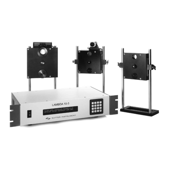
9. Loading port (plug installed) 10. Shutter housing Figure 1-1. Lambda 10-3 filter wheel (without shutter). Figure 1-2. Lambda 10-3 filter wheel housing (with shutter). Figure 1-3. Lambda 10-3 filter wheel housing with SmartShutter. 1.3.2 Filter Wheels 1.3.2 Filter Wheels 1.3.2 1.3.2 Filter Wheels... -
Page 16: 1.3.2.1 Mechanical Description
Lambda 10-3 controller must be modified by Sutter Instrument Co. before said filter wheel with shutter is connected. If the 32mm filter wheel is not equipped with a shutter, or if installing a 50mm filter wheel, then no modification to the Lambda 10-3 controller is needed. -
Page 17: Slide-In Or Drop-In Filter Holders
9 mm (0.35 in.) for Filter cups Instructions for installing filters into the filter wheel can be found in the FILTER WHEEL chapter of this manual. Filters are not supplied by Sutter Instrument Company but filters Filters are not supplied by Sutter Instrument Company but filters... -
Page 18: Smartshutter Mounts
Posts of various lengths are available from Sutter Instrument Co. This post, along with posts of other dimensions, as well as post holders and bases, are available from most laboratory equipment suppliers. -
Page 19: Smartshutter
1.4 SmartShutter SmartShutter SmartShutter SmartShutter The SmartShutter is a lightweight motor-driven aluminum vane under microprocessor control. Because of the microprocessor control, the motion of the vane can be tailored for different roles. The vane starts and stops under motor control, eliminating the sharp jolt typical of other fast shutters. -
Page 20: Figure 1-4. 25Mm Smartshutter (Standalone)
Figure 1-4. 25mm SmartShutter (standalone). Figure 1-5. 35mm SmartShutter (standalone). LAMBDA 10-3 OPERATION MANUAL – REV. 3.03 (20110829) -
Page 21: Modes
Figure 1-6. 25mm SmartShutter mounted on the housing of a 25mm Filter Wheel. The following figure shows a 35mm SmartShutter mounted on a 32mm Filter Wheel housing. Figure 1-7. 35mm SmartShutter mounted on 32mm Filter Wheel Assembly. 1.4.2 1.4.2 Modes 1.4.2 1.4.2 Modes... -
Page 22: Special Considerations
In this mode the user selects the extent to which the shutter opens. When used with the Sutter Instrument light guide system (LLG), this allows the light output from the light guide to be attenuated without changing its wavelength or spatial distribution. -
Page 23: 1.4.3.3 Repetition Rates And Duty Cycle
Figure 1-8. SmartShutter timing. The timing of a SmartShutter is shown in the figure above. The bottom trace is a TTL signal, the middle trace is a 25 mm SmartShutter, and the upper trace is a 35 mm SmartShutter. Operation is slower in the ND (Neutral Density) and SOFT modes. In the SOFT mode, the SmartShutter has a typical time to open of 60 msec. -
Page 24: Controller
commands. This is close to the absolute minimum time in either the open or closed state. If you attempt to reduce the time in either state below 12 msec, the controller will not start to change the shutter state until the 12-msec minimum period is over. 1.5 Controller Controller Controller... -
Page 25: Figure 1-10. Generation 2 Rear Panel Electrical Connections
Figure 1-10. Generation 2 rear panel electrical connections Figure 1-11. Generation 3 rear panel electrical connections). Figure 1-12. Generation 4 rear panel electrical connections. WHEEL A WHEEL A (Gen 1 (Gen 1 – – – – 3) or A (Gen 4) 3) or A (Gen 4) WHEEL A WHEEL A... - Page 26 SmartShutter is attached to the 25 SmartShutter is attached to the 25- - - - pin connector. Do not attempt to attach two filter pin connector. Do not attempt to attach two filter SmartShutter is attached to the 25 SmartShutter is attached to the 25 pin connector.
-
Page 27: Front Panel Controls
FUSE FUSE: Fuse compartment containing the supply voltage fuse and an extra fuse. Replace FUSE FUSE blown fuses with a fuse of the appropriate value as given on the fuse label (back panel of the controller) or on the TECHNICAL SPECIFICATIONS page in this manual. 1.5.3 1.5.3 Front Panel Controls 1.5.3... -
Page 28: 1.5.3.3 Display
During this initialization process, the following is displayed on the controller’s display. FILTER WHEEL CONTROLLER PROGRAM V1.21 COPYRIGHT SUTTER INSTRUMENT CORP 2004 After the controller has finished initializing, the status screen is displayed. WHEEL: A-25MM 0 1 B-NC... -
Page 29: Functional Description
2. Port Bay C C C C supports one standalone filter wheel. No shutter support is provided. A filter wheel with integrated shutter can be connected to Port Bay C, but the shutter will be inoperative. 1.7 Functional Description Functional Description Functional Description Functional Description 1.7.1... - Page 30 position an external sensor must be added. Absolute position only needs to be determined once so long as the subsequent moves occur without errors. Correct operation of stepping motors, which is outlined above, is not always obtained. If the motor lacks the torque to accelerate and decelerate the load at the rate indicated by the control electronics, the resulting move may differ from that commanded by the control electronics.
-
Page 31: Installation
2. 2. 2. 2. INSTALLATIO INSTALLATIO N N N N INSTALLATIO INSTALLATIO 2.1 Unpacking Unpacking Unpacking Unpacking The Lambda 10-3 and associated hardware comes packed in a single carton. The following is a list of the components found there. If you believe that any of these components are missing or show obvious signs of damage from shipping, please contact the factory. -
Page 32: Pre-Installation Considerations
A disc (CD-ROM) containing the USB device drivers, and demo programs for use when either the USB port or the RS-232 serial port is used. Microscope adapters (if ordered). Each 10-position filter wheel is shipped with nine positions of the wheel containing retaining rings, spacer rings and blanking discs. -
Page 33: Installing The Filter Wheel
(Figure 2-1). If you need to purchase an adapter or require a custom adapter for your experimental setup, please contact the Technical Support staff at Sutter Instrument Company by phone (415 883-0128) or by E-mail (info@sutter.com). -
Page 34: Filter Wheel Assembly
table top or optical bench. When using the support rod base always secure it to the table top using the toe clamps provided with the system. If a heavy light source is to be used (such as a vapor lamp with integral igniter) it should have its own separate support system. -
Page 35: Loading Filters
ends be tight to insure a good connection for the motor power leads and positioning signals. Figure 2-3. Filter wheel connection. CAUTION: CAUTION: DO NOT CONNECT OR DISCONNECT THE CABLES BETWEEN DO NOT CONNECT OR DISCONNECT THE CABLES BETWEEN CAUTION: CAUTION: DO NOT CONNECT OR DISCONNECT THE CABLES BETWEEN DO NOT CONNECT OR DISCONNECT THE CABLES BETWEEN... -
Page 36: Figure 2-4. Filter Holder Components
Figure 2-4. Filter holder components. Retaining Ring. Retaining Ring. Retaining Ring. Retaining Ring. This ring is threaded on its outside surface and has two slots on its top edge. The purpose of the two slots is for the removal and installation of the retaining ring when using the retaining ring driver or spanner wrench that is provided with the Lambda 10-3 (shown in Figure 2-4). -
Page 37: Installation Of Filters Into Filter Holders
Table 2-1. Maximum allowable filter thickness. With Spacer With Spacer With Spacer With Spacer Without Spacer Without Spacer Without Spacer Without Spacer (Millimeters) (Inches) (Millimeters) (Inches) 1.38 Slide Slide Slide Slide- - - - In Holder In Holder In Holder In Holder 0.054 4.56... -
Page 38: Figure 2-6. Removing The Retaining Ring
Figure 2-6. Removing the retaining ring. The threaded retaining ring has two notches cut into it, 180 degrees apart. Place the notched end of the brass spanner wrench (Figure 2-6, right) into the notches on the retaining ring and carefully turn it counter-clockwise to unscrew it. Once the retaining ring is removed, the spacer (and blank, if present) should be easily removed. -
Page 39: Installation Of Filters Into Filter Cups
provide maximum separation between the filter surface and end of the tool that is used to turn the retaining ring. Finally, install the threaded retaining ring. DO NOT OVER TIGHTEN THE RETAINING RING! It need only be tightened until it is firmly seated. 2.5.4 2.5.4 Installation of Filters into Filter Cups 2.5.4... -
Page 40: Figure 2-8. Filter Ports (Plug Is Removed From The Loading Port)
Filter position at optical port Filter position at loading port Figure 2-8. Filter ports (plug is removed from the loading port). After identifying and positioning the filter cup to be loaded, it is advisable to turn off the controller before removing the retaining ring from the filter cup. Follow the procedures described above for installation of filters into filter holders. -
Page 41: Filter Loading Tips
Turn the spanner wrench so that the widest end is toward the filter cup and slip the wrench into the two notches in the edge of the cup. Then turn the wrench clockwise to screw the cup back into the slider. DO NOT push on the cup. Just screw it in until it seats firmly. It should then be possible to remove the retaining ring as described above without the cup turning. -
Page 42: Mounting A Smartshutter In A Lambda Ls
The controller will detect the SmartShutter, if installed. The controller will assume that there is a Uniblitz shutter if no SmartShutter is detected. If you have a Uniblitz shutter, an internal jumper, J21, on the Lambda 10-3 circuit board must be set to the correct position in order to ensure the best performance. -
Page 43: Operations Operations
3. 3. 3. 3. OPERATIONS OPERATIONS OPERATIONS OPERATIONS 3.1 First Time Use First Time Use First Time Use First Time Use 3.1.1 3.1.1 Line Power (Mains) 3.1.1 3.1.1 Line Power (Mains) Line Power (Mains) Line Power (Mains) The power cord provided with the Lambda 10-3 connects to the Power Entry Module located on the back of the unit (see diagram below). -
Page 44: Basic Operation
0 through 4. At power on the first display is the copyright message: FILTER WHEEL CONTROLLER PROGRAM V1.19 COPYRIGHT SUTTER INSTRUMENT CORP 2004 After the copyright screen, the unit display should be similar to: WHEEL: A-25MM 0 1 B-NC... - Page 45 2. The Lambda 10-3 will default to on-line at power-on or after a reset. If the unit is connected to a USB port with properly installed software, the USB port will be selected as the default remote control interface. 3. The Lambda 10-3 will be in the on-line mode at power on, ready for serial port or USB port commands.
- Page 46 (This page intentionally blank.) LAMBDA 10-3 OPERATION MANUAL – REV. 3.03 (20110829)
-
Page 47: Operations: Manual Control Operations: Manual Control
10-position wheel, the controller will only execute moves to filter positions 0 through 3. While the unit is going through these steps, the following screen is displayed: FILTER WHEEL CONTROLLER PROGRAM V1.21 COPYRIGHT SUTTER INSTRUMENT CORP 2004 After the copyright screen, the status screen is displayed: WHEEL: A-25MM 0 1 B-NC... -
Page 48: Setting The Position Of The Active Filter Wheel
4.2 Setting the Position of the Active Filter Wheel Setting the Position of the Active Filter Wheel Setting the Position of the Active Filter Wheel Setting the Position of the Active Filter Wheel Pressing the corresponding numeric key when the controller is in the local mode chooses a filter position on the wheel. -
Page 49: Selecting The Active Filter Wheel For Manual Control (Mode 1)
6. Save and load configurations 7. Set power-up default settings (in Lambda 10-3 Firmware Rev. 1.21 and later) 4.6 Selecting the Active Filter Wheel for Manual Control (MODE 1) Selecting the Active Filter Wheel for Manual Control (MODE 1) Selecting the Active Filter Wheel for Manual Control (MODE 1) Selecting the Active Filter Wheel for Manual Control (MODE 1) When pressing keys 1 through 0 on the keypad while in Local mode, the currently active filter wheel moves to the corresponding filter position. -
Page 50: Selecting Shutter Ttl Control (Mode 3)
Table 4-1. Filter switching times (in milliseconds). Number of Filter Positions Moved Number of Filter Positions Moved Number of Filter Positions Moved Number of Filter Positions Moved Speed Setting Speed Setting 1 1 1 1 2 2 2 2 3 3 3 3 4 4 4 4 5 5 5 5 Speed Setting... -
Page 51: Selecting A Test Mode (Mode 4)
4.9 Selecting a Test Mode (MODE 4) Selecting a Test Mode (MODE 4) Selecting a Test Mode (MODE 4) Selecting a Test Mode (MODE 4) Up to four test/demo modes can be selected from the menu that is displayed when MODE and 4 are pressed. -
Page 52: Saving And Restoring Smartshutter Mode Configurations (Mode 6)
4.11 4.11 Saving and 4.11 4.11 Saving and Saving and Saving and Restoring SmartShutter Mode Configurations (MODE 6) Restoring SmartShutter Mode Configurations (MODE 6) Restoring SmartShutter Mode Configurations (MODE 6) Restoring SmartShutter Mode Configurations (MODE 6) WHEEL: A-25MM 0 1 B-NC C-NC SHUTR: A-N(5/144) OFF B-... -
Page 53: Setting The Position (Filter) Defaults For Wheels A, B, & C (Mode 7 1 5|6|7 [0 - 7])
4.12.1.2 Setting the Position (Filter) Defaults for Wheels A, B, & C (MODE 7 1 5|6|7 [0 – 7]) Please enter the default filter value between 0-9…… PLEASE ENTER THE NEW DEFAULT FILTER VALUE BETWEEN 0-9..4.12.1.3 Setting the Default Communications Port (MODE 7 1 4) MODE 7 1 4 (comm. -
Page 54: Table 4-2. Factory Defaults For Filter Wheels, Smartshutters, And Communications Ports
Table 4-2. Factory defaults for filter wheels, SmartShutters, and communications ports. Device Device Device Device Setting Setting Setting Setting Position (Filter) Speed Position (Filter) Filter Wheels Speed Position (Filter) Speed Mode Fast SmartShutters Mode Fast Mode Fast Remote Control Communications Port “U”... -
Page 55: Operations Overview
5. 5. 5. 5. EXTERNAL EXTERNAL COMMAND COMMAND CONTROL OPERATIONS CONTROL OPERATIONS OVERVIEW OVERVIEW EXTERNAL EXTERNAL COMMAND COMMAND CONTROL OPERATIONS CONTROL OPERATIONS OVERVIEW OVERVIEW The remote control of the Lambda 10-3 can be achieved by issuing commands on a remote computer and transmitting them to the Lambda 10-3 over a serial serial serial... -
Page 56: Table 5-2. Remote Control Commands
Table 5-2. Remote Control Commands. Command Command Value Value Description Description Command Command Value Value Description Description (Decimal, (Decimal, (Decimal, (Decimal, hexadecimal, & hexadecimal, & hexadecimal, & hexadecimal, & binary) binary) binary) binary) Set filte Set filter wheel, r wheel, (See Table 5-3 for Sets the filter wheel (A, B, or C), the filter wheel Set filte... - Page 57 Command Command Command Command Value Value Value Value Description Description Description Description (Decimal, (Decimal, (Decimal, (Decimal, hexadecimal, & hexadecimal, & hexadecimal, & hexadecimal, & binary) binary) binary) binary) executed in quick succession. Status Status Returns status of unit in two bytes Status Status 11001100...
- Page 58 Command Command Command Command Value Value Value Value Description Description Description Description (Decimal, (Decimal, (Decimal, (Decimal, hexadecimal, & hexadecimal, & hexadecimal, & hexadecimal, & binary) binary) binary) binary) Transfer to On Transfer to On Puts controller on-line Transfer to On Transfer to On Line Line...
-
Page 59: Filter Wheel Commands
The microprocessor in the controller is programmed to distinguish between these two types of input commands based on the bit pattern of the command and will respond accordingly. These two types of commands are discussed in more detail in the following sections. The following table shows the command byte value ranges for filter commands and those for shutter/special commands. -
Page 60: Table 5-4. Filter Command Structure
Command byte, three parameters are encoded: Filter Wheel, Speed, and Position. The accommodation of these three parameters within a single byte is accomplished by breaking up the byte into three parts: two bit groups, and one single bit, as follows. WHEEL BIT: WHEEL BIT: WHEEL BIT:... -
Page 61: Filter Wheel Command Byte Encoding
In the previous table, “Decimal Group Values” are equivalent to the values of the desired Filter Wheel (always 0), Switching Speed (0 through 7) and Filter Position (0 through 9). Their hexadecimal and binary equivalents are shown as the “Hexadecimal Group Values” and “Binary Group Values”, respectively. - Page 62 Command Command Command Command Value Value Value Value Description Description Description Description (Decimal, hexadecimal, & binary) Close Shutter A Close Shutter A Close Shutter A Close Shutter A Sets the state of Shutter A closed. 10101100 Open Shutter B Open Shutter B Sets the state of Shutter B to open.
-
Page 63: Open Shutter A
NOTE: The commands for Shutter C are available only in the Lambd NOTE: The commands for Shutter C are available only in the Lambda 10 a 10- - - - 3 Generation 4. 3 Generation 4. NOTE: The commands for Shutter C are available only in the Lambd NOTE: The commands for Shutter C are available only in the Lambd a 10 a 10... -
Page 64: Special Commands
command ends with a third byte, which contains a value of 1 through 144 indicating the number of microsteps. 5.4 Special Commands Special Commands Special Commands Special Commands Special commands are those that are not specifically related to the control of filter wheels or shutters. -
Page 65: Batch Start And Batch End
Command Command Command Command Value Value Value Value Description Description Description Description (Decimal, hexadecima l, & binary) ) ) ) Transfer to Transfer to Puts controller in local mode Transfer to Transfer to Local Local Local Local 11101111 Reset Reset Resets the controller Reset Reset... - Page 66 Order Order Order Order Num. Num. Num. Num. Category Category Category Category Value Value Value Value Description Description Description Description of of of of Category Category Category Category (Decimal, bytes bytes bytes bytes hexadecimal, & binary) Filter Filter Wheel, Wheel, Encoded command Filter Filter...
-
Page 67: All Motors Power On
Order Order Order Order Num. Num. Num. Num. Category Category Category Category Value Value Value Value Description Description Description Description of of of of Category Category Category Category (Decimal, bytes bytes bytes bytes hexadecimal, & binary) Fast Fast Fast Fast 220 + 1 Indicates that SmartShutter A is in the fast mode. -
Page 68: All Motors Power Off
5.4.4 All Motors Power Off 5.4.4 All Motors Power Off 5.4.4 5.4.4 All Motors Power Off All Motors Power Off This command is used to instruct the controller to switch OFF electrical power to the motors of all connected filter wheels and shutters. 5.4.5 5.4.5 Batch Transfer 5.4.5... -
Page 69: Shutter Control Without Remote Commands Via Dedicated Ttl Line
Table 5-8. “Get Controller Type and Configuration” command return codes and data. Total Total Total Total Description Num. Num. Num. Num. Category Possible Values Bytes Bytes Bytes Bytes ASCII Meaning Byte String Controller Type 10-3 Lambda 10-3 WA-25 25mm WA-32 32mm WA-HS High Speed... -
Page 70: Remote Control Command Programming
5.6 Remote Control Command Programming Remote Control Command Programming Remote Control Command Programming Remote Control Command Programming This section describes some suggested tips and techniques when writing programs on the remote control computer for communicating with the Lambda 10-3 via either the serial RS- 232 port or the USB (Universal Serial Bus) port. -
Page 71: 5.6.1.2 Shutter Or Special Commands
5.6.1.2 Shutter or Special Commands Shutter and Special Commands make use of the remaining command byte bit patterns not being used by Filter Commands. 5.6.2 5.6.2 Command Transmission Protocol 5.6.2 5.6.2 Command Transmission Protocol Command Transmission Protocol Command Transmission Protocol The Lambda 10-3 does not use any of the standard protocols commonly used for serial line or USB communications between computers or between a computer and a peripheral device. - Page 72 (This page intentionally blank.) LAMBDA 10-3 OPERATION MANUAL – REV. 3.03 (20110829)
-
Page 73: External Serial Rs External Serial Rs
6. 6. 6. 6. EXTERNAL SERIAL RS EXTERNAL SERIAL RS- - - - 232 INTERFACE CONTROL 232 INTERFACE CONTROL EXTERNAL SERIAL RS EXTERNAL SERIAL RS 232 INTERFACE CONTROL 232 INTERFACE CONTROL The Lambda 10-3 microprocessor sets the serial RS-232C port, by default, as the input source upon startup and anytime the ON LINE key is pressed. -
Page 74: Input Command Set And Protocol
communication that you use. In Microsoft QuickBasic the communication channel may be opened with a statement such as: OPEN "COM1:9600,N,8,1, CD0,CS0,DS0 " FOR RANDOM AS #1 LEN = 256 This sets COM1 to the correct mode for bi-directional communication through channel #1. The option list “CD0,CS0,DS0”... -
Page 75: External Usb Interface Control
7. 7. 7. 7. EXTERNAL USB INTERFACE CONTR EXTERNAL USB INTERFACE CONTR OL EXTERNAL USB INTERFACE CONTR EXTERNAL USB INTERFACE CONTR The Lambda 10-3 can communicate with the computer via the Universal Serial Bus (USB) port instead of the SERIAL (RS-232) port whenever it is connected to the remote computer with a USB cable and the appropriate USB device drivers are installed. -
Page 76: Installation Steps
5. Windows Advanced Server 2003 or 2008 (32-bit only) 6. Windows Vista (all editions, 32-bit only) 7. Windows 7 (all editions, 32-bit only) The standard device driver for the Lambda 10-3 can be downloaded from the following location: http://www.sutter.com/software/Lambda_10-3_USB_device_driver_Win_v1_06_20.zip Extract the contents of the downloaded device driver archive file into a folder and disk drive of your choosing. -
Page 77: Interactive Usb Device Driver Installation
Windows may also automatically install the appropriate drivers if another Sutter Instrument Company instrument with a USB interface (such as a Lambda 10-B, a Lambda SC, an MPC-200, or even another Lambda 10-3) is already connected and configured with your computer. -
Page 78: Figure 7-6 -- Digital Signature Dialog Box
Figure 7-6 -- Digital Signature dialog box. Do not be concerned that Windows is unable to find a Microsoft digital signature for the Lambda 10-3 as shown in Figure 7-6. Simply press the “Yes” button to continue to the next step. -
Page 79: Driver Model) Device Driver
2. Select from the memory list in the “Copy files from” combo box, by pressing the inverted triangle to the right of the combo box, and then selecting and clicking on one of the items (if any) displayed in the pulldown list, and finally pressing OK. 3. -
Page 80: Installing The Usb Interface For Non-Windows Systems
Instrument Co.’s web site (www.sutter.com). The files that make up the distribution of the USBTest program include the Setup program. Simply run this setup program to install USBTest on your system (Windows-based systems only. The USB Test & Demo program can be downloaded from Sutter Instrument’s web site using the following link: http://www.sutter.com/software/Lambda_10-3&10-B_DemoTest_USB_Win_v2_20.zip... -
Page 81: Figure 7-9 Usbtest Main Screen
http://www.sutter.com/software/Lambda_10-3&10-B_DemoTest_Com_Win_v2_20.zip The USBTest program has only one screen, and appears as shown in the following figure. Figure 7-9 USBTest main screen. Once you have the program up and running and the screen in the previous figure is displayed, you can use the program to first identify whether or not one or more Lambda 10-3 units are installed as USB devices. -
Page 82: Uninstalling The Usb Driver For The Lambda 10-3
written in C and C++ and includes the use of the MFC (Microsoft Foundation Classes) library included with Microsoft Visual C++ (or Studio) Version 6.0. The USBTest program also makes use of a library called FTDIXXX .DLL that is freely available from FTDI, the manufacturer of the USB chip set used in the Lambda 10-3 and which gets installed on your system when the USB device driver for the Lambda 10-3 is installed. -
Page 83: Remote Commands And The Usb Interface
system during the installation process, without requiring you to supply the disk containing the driver. If you wish to completely remove the USB driver and related files from the system, use either of the following two methods. 1. Manually delete the file FTD2XX.sys from the “system32” directory in your Windows directory. - Page 84 (This page intentionally blank.) LAMBDA 10-3 OPERATION MANUAL – REV. 3.03 (20110829)
-
Page 85: External Parallel Interface Control External Parallel Interface Control
8. 8. 8. 8. EXTERNAL PARALLEL INTERFACE CONTROL EXTERNAL PARALLEL INTERFACE CONTROL EXTERNAL PARALLEL INTERFACE CONTROL EXTERNAL PARALLEL INTERFACE CONTROL In Lambda 10-3’s programmed with firmware version 1.21 or later, the parallel port is enabled for use. When configured to do so, the Lambda 10-3 microprocessor sets the PARALLEL port as the input source upon startup and anytime the ON LINE key is pressed. -
Page 86: Input Command Structure
Table 8-1. Lambda 10-3 Parallel Interface Pin Assignments Pin # Pin # Pin # Pin # Function Function Function Function Not Connected (NC) Bit 0 for Filter Position Bit 1 for Filter Position Bit 2 for Filter Position Bit 3 for Filter Position Bit 0 for Speed Bit 1 for Speed Bit 2 for Speed... -
Page 87: Filter Commands
The microprocessor is programmed to distinguish between these two types of input commands based on the bit pattern of the command, and will respond accordingly. These two types of commands are discussed in more detail in the following sections. 8.2.1 8.2.1 Filter Commands 8.2.1 8.2.1... -
Page 88: Special Commands: On Line, Batch, And Shutter Commands
9) has changed from the previous query, and if the new filter group value (pins 2 - 5) are in the range of 0 to 9, the controller will respond as commanded with a change in the filter position of the appropriate filter wheel. In the above example (Table 8-2), Filter Wheel A will move to Filter Position 7, using Speed 5. -
Page 89: Strategies For Controlling The Lambda 10-3 Via The Parallel Port
Error Line (Pin #12). Error Line (Pin #12). Error Line (Pin #12). Error Line (Pin #12). — — — — The ERROR ERROR ERROR ERROR signal indicates that an error has been detected and error recovery is in progress. The controller uses optical and magnetic sensors to verify that the correct filter is in position. -
Page 90: Using The Busy Line
8.4.3 Using the BUSY Line 8.4.3 Using the BUSY Line 8.4.3 8.4.3 Using the BUSY Line Using the BUSY Line Reading the status of the BUSY BUSY line would allow the host computer to determine if the unit BUSY BUSY is ready to receive a command, if a command has been received, and when the new filter has been placed in position. -
Page 91: Connecting To The Pc Parallel (Printer) Port
However, given the wide range of hardware and software in use, it is impossible to anticipate all possible problems. Sutter Instrument Company thus cannot be responsible for any damages Sutter Instrument Company thus cannot be responsible for any damages... -
Page 92: Input Command Structure
Table 8-3. PC and Lambda 10-3 parallel port pin assignments Pin # Pin # Pin # Pin # PC Parallel Port PC Parallel Port PC Parallel Port PC Parallel Port Lambda 10 Lambda 10- - - - 3 Controller Lambda 10 Lambda 10 3 Controller 3 Controller... -
Page 93: Output Command Structure: Busy And Error Lines
8.5.3 Output Command Structure: BUSY and ERROR Lines 8.5.3 Output Command Structure: BUSY and ERROR Lines 8.5.3 8.5.3 Output Command Structure: BUSY and ERROR Lines Output Command Structure: BUSY and ERROR Lines The section Output Commands has a detailed explanation of the BUSY BUSY and ERROR ERROR signals. -
Page 94: Dedicated Ttl Line
port reads as the indicated by data expressions. The AND data expression is evaluated as an AND operation. Thus, we may test to see if the BUSY line is set as follows: WAIT 889, 128 The program will suspend operation until the value read for the most significant bit is 1. Since the printer adapter inverts this bit, this condition will be met only when the BUSY line is low. -
Page 95: Table 8-5. Computer Parallel Port Commands For Ttl Control Of Shutters
shutter. Pin 14 can be set high to open the shutter by sending a value such as 0. The logic for pin 16 is the reverse of pin 14. To open shutter B, send a value of 4 to the port. To close shutter B, send 0 to the port. - Page 96 (This page intentionally blank.) LAMBDA 10-3 OPERATION MANUAL – REV. 3.03 (20110829)
-
Page 97: Operating Instructions: External Logic Level (Ttl) Shutter Control Operating Instructions: External Logic Level (Ttl) Shutter Control
9. 9. 9. 9. OPERAT OPERATING INSTRUCTIONS: EXTERNAL LOGIC LEVEL (TTL) ING INSTRUCTIONS: EXTERNAL LOGIC LEVEL (TTL) OPERAT OPERAT ING INSTRUCTIONS: EXTERNAL LOGIC LEVEL (TTL) ING INSTRUCTIONS: EXTERNAL LOGIC LEVEL (TTL) SHUTTER CONTROL SHUTTER CONTROL SHUTTER CONTROL SHUTTER CONTROL In addition to the control of the shutter via the keypad, serial port, USB port and the parallel port, the direct TTL logic input can also control the shutter. -
Page 98: Figure 9-1. Location Of Ttl In Jumpers On The Lambda 10-3 Controller Board
position, the TTL IN for the selected shutter (A or B) is active on the corresponding BNC connector mounted externally on the rear of the controller cabinet. The jumpers are accessed by removing the top of the controller cabinet. Carefully remove the eight screws from the top of the cabinet, and two screws from the upper part of each side. -
Page 99: Enabling/Disabling And Setting The Type Of Ttl In Control
TTL IN control active on Shutter A Parallel port pins 14 (Shutter jumper A) and 16 (Shutter B) TTL IN control active Shutter B on BNC connectors. jumper Figure 9-2. TTL IN jumpers detail. 9.2 Enabling/Disabling and Setting the Type of TTL IN Control Enabling/Disabling and Setting the Type of TTL IN Control Enabling/Disabling and Setting the Type of TTL IN Control Enabling/Disabling and Setting the Type of TTL IN Control... - Page 100 WHEEL: A-25MM 0 1 B-NC C-NC SHUTR: A- OFF B-FAST After the Lambda 10-3 has been placed in the local off-line mode, the TTL IN settings menu is reached by first pressing the MODE key, which displays the Mode Menu as shown next. 1-ACTIVE WHEEL 2-SPEED 3-TTL...
-
Page 101: 10. Maintenance
10. MAINTENANCE MAINTENANCE MAINTENANCE MAINTENANCE Routine cleaning of the Lambda 10-3 system is required to prevent excessive dust accumulations. This is done by wiping all exterior surfaces with a dry, soft, cotton cloth. All retaining rings should be inspected occasionally to be certain that they are seated into the filter holders and cups. - Page 102 (This page intentionally blank.) LAMBDA 10-3 OPERATION MANUAL – REV. 3.03 (20110829)
-
Page 103: Filter Wheel Error Detection And Recovery
11. TROUBLESHOOTING TROUBLESHOOTING TROUBLESHOOTING TROUBLESHOOTING 11.1 11.1 Filter Wheel Error Detection and Recovery 11.1 11.1 Filter Wheel Error Detection and Recovery Filter Wheel Error Detection and Recovery Filter Wheel Error Detection and Recovery The LAMBDA 10 LAMBDA 10- - - - 3 3 3 3 contains two sensor systems that are used to monitor the actual position LAMBDA 10 LAMBDA 10 of the filter wheel. -
Page 104: Movement Errors After Successive Moves
resonance frequency (see Appendix A). Selecting a higher or lower speed will generally solve this problem. 11.2.4 11.2.4 Movement Errors after Successive Moves 11.2.4 11.2.4 Movement Errors after Successive Moves Movement Errors after Successive Moves Movement Errors after Successive Moves With an optimal combination of speed and load-weight, it may be possible to give a new command as soon as the last move is complete. - Page 105 of the next when the delay between moves is slight. This can occur even when the delay between moves is less than 50 msec. The 1-inch version of the SmartShutter can operate at opening rates up to about 20 Hz without problems.
- Page 106 (This page intentionally blank.) LAMBDA 10-3 OPERATION MANUAL – REV. 3.03 (20110829)
-
Page 107: Appendix A. Limited Warranty Appendix A. Limited Warranty
LIMITED WARRANTY LIMITED WARRANTY Sutter Instrument Company, a division of Sutter Instrument Corporation, limits the warranty on this instrument to repair and replacement of defective components for one year after the date of shipment, provided the instrument has been operated in accordance with the instructions outlined in this manual. - Page 108 (This page intentionally blank.) LAMBDA 10-3 OPERATION MANUAL – REV. 3.03 (20110829)
-
Page 109: Accessories
APPENDIX B. APPENDIX B. ACCESSORIES ACCESSORIES APPENDIX B. APPENDIX B. ACCESSORIES ACCESSORIES B.1. B.1. Filter Wheels B.1. B.1. Filter Wheels Filter Wheels Filter Wheels LB10 LB10 LB10 LB10- - - - NW 10-position 25mm filter wheel without shutter. LB10 LB10 LB10 LB10- - - - NWIQ NWIQ... -
Page 110: Smartshutter
B.2. B.2. SmartShutter B.2. B.2. SmartShutter SmartShutter SmartShutter IQ12 IQ12- - - - SA 12.5mm SmartShutter with standalone housing. IQ12 IQ12 1 1 1 1 IQ25 IQ25 IQ25 IQ25- - - - SA 25mm SmartShutter with standalone housing. 2 2 2 2 IQ25 IQ25 IQ25... -
Page 111: Appendix C. Fuse Replacement Appendix C. Fuse Replacement
APPENDIX C. APPENDIX C. FUSE REPLACEMENT FUSE REPLACEMENT APPENDIX C. APPENDIX C. FUSE REPLACEMENT FUSE REPLACEMENT In the event that the controller fails to power up when the power switch is turned on, check the line power fuses to see if either or both have blown. The fuses are located in the fuse holder on the power entry module on the back of the controller. - Page 112 (This page intentionally blank.) LAMBDA 10-3 OPERATION MANUAL – REV. 3.03 (20110829)
-
Page 113: Appendix D. Technical Specif Appendix D. Technical Specifications Appendix D. Technical Specif Ications
APPENDIX D. APPENDIX D. TECHNICAL SPECIFICAT TECHNICAL SPECIFICATIONS IONS APPENDIX D. APPENDIX D. TECHNICAL SPECIFICAT TECHNICAL SPECIFICAT IONS IONS D.1. Controller D.1. Controller D.1. D.1. Controller Controller Dimensions (H x W x D) Dimensions (H x W x D): : : : 4 x 15.94 x 11 in (10.16 x 40.49 x 27.94 cm) 4 x 15.94 x 11 in (10.16 x 40.49 x 27.94 cm) Dimensions (H x W x D) - Page 114 Controller Rear Panel Controller Rear Panel Cable Connector Cable Connector Connects to ... Connects to ... Cable Type Cable Type Cable Cable Controller Rear Panel Controller Rear Panel Cable Connector Cable Connector Connects to ... Connects to ... Cable Type Cable Type Cable Cable...
-
Page 115: Table D-2. Lambda 10-3 2010 Version Controller Cables
Controller Rear Panel Controller Rear Panel Cable Connector Cable Connector Connects to ... Connects to ... Cable Type Cable Type Cable Cable Controller Rear Panel Controller Rear Panel Cable Connector Cable Connector Connects to ... Connects to ... Cable Type Cable Type Cable Cable... - Page 116 Controller Rear Panel Controller Rear Panel Cable Connector Cable Connector Connects to ... Connects to ... Cable Type Cable Type Cable Cable Controller Rear Panel Controller Rear Panel Cable Connector Cable Connector Connects to ... Connects to ... Cable Type Cable Type Cable Cable...
-
Page 117: Filter Wheel, 25 Mm (1")
D.2. D.2. Filter Wheel, 25 mm (1”): D.2. D.2. Filter Wheel, 25 mm (1”): Filter Wheel, 25 mm (1”): Filter Wheel, 25 mm (1”): Dimensions (Height (from motor top to Dimensions (Height (from motor top to Dimensions (Height (from motor top to Dimensions (Height (from motor top to shutter bottom)): shutter bottom)):... -
Page 118: Smartshutter, 35 Mm (1.38 In) (Standalone)
D.5. D.5. D.5. D.5. SmartShutter, 35 mm (1.38 in) (standalone): SmartShutter, 35 mm (1.38 in) (standalone): SmartShutter, 35 mm (1.38 in) (standalone): SmartShutter, 35 mm (1.38 in) (standalone): Dimensions (Hei Dimensions (Hei Dimensions (Hei Dimensions (Height (from motor top to ght (from motor top to ght (from motor top to ght (from motor top to... -
Page 119: Appendix F. External Control Command Reference Appendix F. External Control Command Reference
APPENDIX F. APPENDIX F. EXTERNAL CONTROL COM EXTERNAL CONTROL COM MAND REFERENCE MAND REFERENCE APPENDIX F. APPENDIX F. EXTERNAL CONTROL COM EXTERNAL CONTROL COM MAND REFERENCE MAND REFERENCE This appendix provides a complete list of remote control commands and return values. Table F-3. - Page 120 Command Byte Value Command Byte Value Keyboard Entry Keyboard Entry Description Description Command Byte Value Command Byte Value Keyboard Entry Keyboard Entry Description Description Dec. Dec. Dec. Dec. Hex. Hex. Hex. Hex. Binary Binary Binary Binary Alt- - - - Ctrl Ctrl Ctrl...
- Page 121 Command Byte Value Command Byte Value Keyboard Entry Keyboard Entry Description Description Command Byte Value Command Byte Value Keyboard Entry Keyboard Entry Description Description Dec. Dec. Dec. Dec. Hex. Hex. Hex. Hex. Binary Binary Binary Binary Alt- - - - Ctrl Ctrl Ctrl...
- Page 122 Command Byte Value Command Byte Value Keyboard Entry Keyboard Entry Description Description Command Byte Value Command Byte Value Keyboard Entry Keyboard Entry Description Description Dec. Dec. Dec. Dec. Hex. Hex. Hex. Hex. Binary Binary Binary Binary Alt- - - - Ctrl Ctrl Ctrl...
- Page 123 Command Byte Value Command Byte Value Keyboard Entry Keyboard Entry Description Description Command Byte Value Command Byte Value Keyboard Entry Keyboard Entry Description Description Dec. Dec. Dec. Dec. Hex. Hex. Hex. Hex. Binary Binary Binary Binary Alt- - - - Ctrl Ctrl Ctrl...
-
Page 124: Table F-4. Filter Command Structure
Command Byte Value Command Byte Value Keyboard Entry Keyboard Entry Description Description Command Byte Value Command Byte Value Keyboard Entry Keyboard Entry Description Description Dec. Dec. Dec. Dec. Hex. Hex. Hex. Hex. Binary Binary Binary Binary Alt- - - - Ctrl Ctrl Ctrl... -
Page 125: Table F-5. Status Command Return Codes And Data
Encoding filter wheel commands into a single byte: wheel speed position Command byte = ( * 128) + ( * 16) + wheel Where 0 (Wheel A or C) or 1 (Wheel B), speed 0 through 7, and position 0 through 9. NOTE: Wheel C is differentiated from Wheel A by having its command byte preceded by the “Wheel C First Byte”... - Page 126 Order Order Num. Order Order Num. Num. Num. Category Category Category Category Sub Category Sub Category Sub Category Sub Category Value Value Value Value Description Description Description Description of of of of (Decimal, bytes bytes bytes bytes hexadecimal, & binary) Closed Closed Closed...
-
Page 127: Table F-6. Get Controller Type And Configuration Command Return Data
Order Order Num. Order Order Num. Num. Num. Category Category Category Category Sub Category Sub Category Sub Category Sub Category Value Value Value Value Description Description Description Description of of of of (Decimal, bytes bytes bytes bytes hexadecimal, & binary) Neutral Neutral Neutral... - Page 128 (This page intentionally blank.) LAMBDA 10-3 OPERATION MANUAL – REV. 3.03 (20110829)
-
Page 129: Index
INDEX INDEX INDEX INDEX electrical connections ........12 A A A A principles of operation........12 accessories ............4, 97 D D D D adapters specifications ............6 dimensions controller ............101 B B B B filter wheel (25mm (1in))....... 105 basic operation ............32 filter wheel (32mm (1.27in))...... - Page 130 P P P P replacement..........15, 99 spare..............99 packaging..............20 fuses, replacement fuses, replacement fuses, replacement fuses, replacement parallel interface mains mains............iii, 101 mains mains connection ............73 I I I I output lines ............76 PC pin assignments...........79 input commands PC printer ports..........78 serial interface pin assignments ..........73 command set ..........62...
- Page 131 Opening and closing times......10 technical specifications Repetition rates and duty cycle ....11 weight Step motor based shutter advantages ....7 SmartShutter (25mm (1in)) ...... 105 use with other Sutter Instrument Co. products technical specifications ................6 SmartShutter (35mm (1.38in)) ..... 106 spacer rin spacer rin spacer rin spacer ring g g g ..............24...
- Page 132 NOTES NOTES NOTES NOTES LAMBDA 10-3 OPERATION MANUAL – REV. 3.03 (20110829)
Need help?
Do you have a question about the LB10-3 and is the answer not in the manual?
Questions and answers