
Related Manuals for Sutter Instrument P-97


Summary of Contents for Sutter Instrument P-97
- Page 1 P-97 Flaming/Brown™ Micropipette Puller Operation Manual Rev. 2.43 - DOM ( 20161118) One Digital Drive Novato, CA 94949 Voice: 415-883-0128 Web: www.sutter.com Fax: 415-883-0572 Email: info@sutter.com...
- Page 2 Copyright © 2016 Sutter Instrument Company. All Rights Reserved. Flaming/Brown™ is a trademark of Sutter Instrument. P-97 FLAMING/BROWN MICROPIPETTE PULLER OPERATION MANUAL – REV. 2.43 - DOM (20161118)
-
Page 5: Disclaimer
Electrical • Operate the P-97 using 110-120 V AC, 60 Hz, or 220-240 V AC., 50 Hz line voltage. This instrument is designed for connection to a standard laboratory power outlet (Overvoltage Category II), and because it is a microprocessor--controlled device, it should be accorded the same system wiring precautions as any 'computer type' system. -
Page 6: Back Injury Prevention
To avoid injuring your back or limbs it is recommended that you do not attempt to lift this instrument by yourself. The P-97 Micropipette Puller weighs in excess of 18 kg (over 39 lb) and should be moved by TWO (2) people. -
Page 7: Table Of Contents
3.2.8.1 Entering a New Program ....................16 3.2.8.2 Editing an Existing Program ...................16 3.3 Software Control Functions......................16 3.3.1 RAMP TEST < 1 > .........................17 3.3.2 CHANGE AIR PRESSURE < 2 > ..................18 P-97 FLAMING/BROWN MICROPIPETTE PULLER OPERATION MANUAL – REV. 2.43 - DOM (20161118) - Page 8 3.6.4 Trough Filament ........................31 3.6.4.1 Positioning..........................32 3.6.4.2 Geometry ..........................32 4. MAINTENANCE..........................33 4.1 Cleaning ............................33 4.2 Heating Filament Replacement ....................33 4.2.1 Filament Replacement (Step by Step) ...................33 4.2.2 Air jet Position..........................33 P-97 FLAMING/BROWN MICROPIPETTE PULLER OPERATION MANUAL – REV. 2.43 - DOM (20161118)
- Page 9 Figure 1-3. P-97 base plate (top view, cover removed)................5 Figure 1-4. Filament Block Assembly...................... 6 Figure 1-5. Upper cable pulley assembly....................7 Figure 2-1. P-97 Cabinet (rear view), showing power entry module..........10 P-97 FLAMING/BROWN MICROPIPETTE PULLER OPERATION MANUAL – REV. 2.43 - DOM (20161118)
- Page 10 Table 3-1. Standard factory configuration.....................14 Table 3-2. Control Functions........................17 Table 3-3. Maximum heat and recommended starting values for different filament shapes..18 Table 3-4. Box filament sizes........................31 Table 3-5. Trough filament sizes......................32 P-97 FLAMING/BROWN MICROPIPETTE PULLER OPERATION MANUAL – REV. 2.43 - DOM (20161118)
-
Page 11: General Information
The P-97 is a ‘velocity sensing’ puller. This patented feature allows the puller to indirectly sense the viscosity of the glass, giving the P-97 the ability to pull pipettes from all glasses except quartz. Even difficult to pull formulations, such as aluminosilicate glasses, are handled with relative ease. -
Page 12: Glass Capillary & Heating Filament Specifications
Examples of the specific types and sizes of glass that can be used with the P-97 are listed in the Sutter Instrument Company catalogue that was included with this instrument or can be viewed on Sutter Instrument’s web site at . -
Page 13: Controls
Aborts the execution of a program. 1.4.2 Display The P-97 has a two line vacuum fluorescent display for easy viewing from any angle. The following figure demonstrates what you will see after you have selected a program. A brief description of each parameter is provided below. - Page 14 If VEL>0 then one unit of DELAY represents 1 (one) millisecond (ms). If VEL=0 (when using fire-polish mode), then one unit represents 10 (ten) ms. SEE THE PROGRAMS SECTION FOR A DISCUSSION OF THE SIGNIFICANCE OF DELAY=0. P-97 FLAMING/BROWN MICROPIPETTE PULLER OPERATION MANUAL – REV. 2.43 - DOM (20161118)
-
Page 15: System Description - Mechanical (Puller Anatomy)
Maintenance Section of this manual. 1.5.2 Air Cooling System The Model P-97 supplies a blast of air to cool the filament area after the heating segment of a pull cycle. The components of the air-cooling system are shown below. -
Page 16: Figure 1-4. Filament Block Assembly
Loosen the locking screw associated with each ‘eccentric screw’ before turning, and tighten after completing the adjustment. Note: Changing the eccentrics should be made only for fine/small adjustments. P-97 FLAMING/BROWN MICROPIPETTE PULLER OPERATION MANUAL – REV. 2.43 - DOM (20161118) -
Page 17: Upper Pulley Assembly
1-5), and contains a large eccentric adjustment screw (J in Figure 1-5). This eccentric screw is used to adjust cable ‘tension’. Its use is covered in the Maintenance Section, and changes to the settings should not be performed without the supervision of Sutter Instrument Technical Support. -
Page 18: Cabinet
1.6.1 Electronics The P-97 micropipette puller is controlled by a Z-80 microprocessor. Three digital-to-analog (D-A) converters control the HEAT, PULL, and VELOCITY values. The HEAT power supply is a precision constant current switching unit, which will vary less than 10 milliamperes with a plus or minus 10% change in the AC line current. -
Page 19: Installation
(see diagram below). This Module also includes the Line Fuse. Unless specified otherwise, the P-97 is shipped equipped with, and configured for, a 2.5mm box heating filament. P-97 FLAMING/BROWN MICROPIPETTE PULLER OPERATION MANUAL – REV. 2.43 - DOM (20161118) -
Page 20: Figure 2-1. P-97 Cabinet (Rear View), Showing Power Entry Module
Figure 2-1. P-97 Cabinet (rear view), showing power entry module. Make certain that the Power Switch located on the left end of the P-97 cabinet is turned OFF. Figure 2-2. P-97 Cabinet (end view, left), showing power switch. Plug the power cord provided with the P-97 into the Line Input socket on the Power Entry Module and then to a power source of the appropriate voltage and frequency. -
Page 21: Operating Instructions
3. OPERATING INSTRUCTIONS 3.1 First Time Use While we realize that most new users of the P-97 are anxious to start pulling useable pipettes right away, we cannot over-state the importance of taking a few moments to review the manual in order to understand how the puller works. Many a heating filament has been destroyed with first use because the user did not understand the relationship between the programmable heat settings and the filament installed in the puller. -
Page 22: Programs
3.2 Programs 3.2.1 Program Structure The resulting size and shape of a micropipette made using the P-97 is determined by the parameter values that are programmed by the user. One hundred (100) separate programs can be saved for future use. Each program is structured as follows: Program Consists of one or more Lines, each of which represents a pull cycle. - Page 23 = 0 (no active cooling). This allows the pulling of special pipette shapes. Most often used to pull long tube-likes shapes such as those used for aspiration, microperfusion, or holding. P-97 FLAMING/BROWN MICROPIPETTE PULLER OPERATION MANUAL – REV. 2.43 - DOM (20161118)
-
Page 24: Pull Cycle
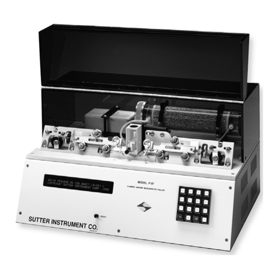
COPYRIGHT SUTTER INSTRUMENT CORP. 1992 Figure 3-2. Power-on display. The P-97 has the capacity to store 100 programs (0 - 99). On the keypad, press < 0 > followed by < ENTR > (factory installed micropipette program) or the number of another program you wish to execute. -
Page 25: Viewing A Program (< Next > / < Last >)
Unused program areas are usually cleared before a puller is shipped, but occasionally test program values are inadvertently left in memory. We recommend that unused programs be cleared before proceeding. P-97 FLAMING/BROWN MICROPIPETTE PULLER OPERATION MANUAL – REV. 2.43 - DOM (20161118) -
Page 26: Entering A New Program
PRESENT CYCLE TO THE END? NO=0 YES=1 Figure 3-5. Access to control functions. Entering < 0 > will provide you with access to the following P-97 CONTROL FUNCTIONS: P-97 FLAMING/BROWN MICROPIPETTE PULLER OPERATION MANUAL – REV. 2.43 - DOM (20161118) -
Page 27: Ramp Test < 1
4. The RAMP TEST value shown on the display is the HEAT value that was required to reach the factory-set RAMP TEST velocity. To interrupt the RAMP TEST or reset the display press RESET. P-97 FLAMING/BROWN MICROPIPETTE PULLER OPERATION MANUAL – REV. 2.43 - DOM (20161118) -
Page 28: Change Air Pressure < 2
(e.g., a setting of 100 will delay the onset of the hard pull by 100 ms). Default TIME MODE Recommendations Use the TIME MODE for: • Sharp microelectrodes and patch pipette programs using P-97 FLAMING/BROWN MICROPIPETTE PULLER OPERATION MANUAL – REV. 2.43 - DOM (20161118) -
Page 29: Air Time At Start Of Pull < 4
Activate (lock) or inactivate (unlock) the WRITE PROTECTION mode. Unlocked mode (0) allows program to be edited. Locked mode (1) prevents program from being edited. The write-protect status is reported on the program header line. P-97 FLAMING/BROWN MICROPIPETTE PULLER OPERATION MANUAL – REV. 2.43 - DOM (20161118) -
Page 30: Memory Test < 8
3.3.8 MEMORY TEST < 8 > Performs a non-destructive test of the RAM. Press RESET to reset the system after performing this test. On newer versions of P-97 pullers, the Memory Test is no longer a valid test. 3.4 Pulling Pipettes 3.4.1 Procedures... -
Page 31: Notes On Program Operation
A unique feature of the P-97 is its capability to loop through a program. This is demonstrated with the multicycle Program 1, which is factory pre-programmed to pull a patch type pipette with a tip diameter of about 2mm. Press RESET to exit Program 0, and then press < 1 >... -
Page 32: Micropipette/Microinjection Needle Fabrication
If you are using a one-line, looping program, try decreasing the VELOCITY a few units at a time. If your program is a P-97 FLAMING/BROWN MICROPIPETTE PULLER OPERATION MANUAL – REV. 2.43 - DOM (20161118) -
Page 33: Time Mode (Cooling)
Under these conditions, the puller will typically execute multiple cycles in order to separate the glass and the glass may break at a large tip diameter. P-97 FLAMING/BROWN MICROPIPETTE PULLER OPERATION MANUAL – REV. 2.43 - DOM (20161118) -
Page 34: Pressure Adjustment
Hard pull is not activated (PULL = 0). More than one heating cycle is used. The P-97 can be used very effectively for this type of processing. The following general information will familiarize you with the effect of adjusting each of the pull cycle parameters in a typical patch pipette program. -
Page 35: Pull Strength
3. Increase the VELOCITY in one unit increments for thick-walled glass and three unit increments for thin-walled glass. Pull a pipette after each adjustment. Note the change in P-97 FLAMING/BROWN MICROPIPETTE PULLER OPERATION MANUAL – REV. 2.43 - DOM (20161118) - Page 36 2 to 3 units, or increase/decrease VELOCITY in last line by 2 to 3 units, or add a small amount of PULL (10 to 20) to last line. P-97 FLAMING/BROWN MICROPIPETTE PULLER OPERATION MANUAL – REV. 2.43 - DOM (20161118)
-
Page 37: Technical Tips For Pulling Micropipettes
(or taper) of a sharp pipette tip. The delay mode is often employed when using thick walled glass or for programs designed for the fabrication of pronuclear injection needles. P-97 FLAMING/BROWN MICROPIPETTE PULLER OPERATION MANUAL – REV. 2.43 - DOM (20161118) -
Page 38: Fire Polishing
3.5.6 Fire Polishing The P-97 micropipette puller allows you to perform light to moderate fire polishing of pipette tips but does not have a provision for visualizing the pipette tip during the heating process. The extent of the heating required to attain the desired degree of polishing must be empirically established. -
Page 39: Heating Filaments
(A or B in Figure 3-1). See the Filament Replacement section of the Maintenance Chapter for a full description of this adjustment. P-97 FLAMING/BROWN MICROPIPETTE PULLER OPERATION MANUAL – REV. 2.43 - DOM (20161118) -
Page 40: Box Filament
3.6.3.1 Positioning When using a box filament, the glass tubing should be centered vertically and horizontally (Figure 3-12). See section Error! Reference source not found. for adjustments and alignment. P-97 FLAMING/BROWN MICROPIPETTE PULLER OPERATION MANUAL – REV. 2.43 - DOM (20161118) -
Page 41: Geometry
Note: The Ramp Test value with a trough filament will be lower than that with the box filament, thus program HEAT values will be correspondingly lower in order to reach similar operating temperatures. P-97 FLAMING/BROWN MICROPIPETTE PULLER OPERATION MANUAL – REV. 2.43 - DOM (20161118) -
Page 42: Positioning
Table 3-5. Trough filament sizes. Filament Description FT315B 1.5mm wide trough FT320B 2mm wide trough FT330B (standard) 3mm wide trough FT345B 4.5mm wide trough P-97 FLAMING/BROWN MICROPIPETTE PULLER OPERATION MANUAL – REV. 2.43 - DOM (20161118) -
Page 43: Maintenance
The correct position of the glass capillary in each of the two filament types is shown above in the Heating Filament section. This positioning is critical to achieving the desired pipette’s tip P-97 FLAMING/BROWN MICROPIPETTE PULLER OPERATION MANUAL – REV. 2.43 - DOM (20161118) -
Page 44: Figure 4-2. Filament Alignment
“seeing” more cooling than the other. Loosen the filament clamping screws and move the filament very slightly towards the side P-97 FLAMING/BROWN MICROPIPETTE PULLER OPERATION MANUAL – REV. 2.43 - DOM (20161118) -
Page 45: Pulley Adjustment
The two cables should not be under high tension when the carriers are against their stops (the position they would be in just before pulling an electrode). P-97 FLAMING/BROWN MICROPIPETTE PULLER OPERATION MANUAL – REV. 2.43 - DOM (20161118) -
Page 46: Regeneration Of Drierite Granules
The Indicating Drierite found in the canister at the right rear corner of the base plate on the P-97 is a desiccant made of calcium sulfate (97%) and cobalt chloride (3%). This material is used to remove water vapor from the air-cooling supply system. The drierite granules become pink as they absorb moisture, eventually requiring that they be “regenerated”... -
Page 47: Reinstalling The Canister
If replacement is necessary, Indicating Drierite (8MESH with Indicator), manufactured by W.A. Hammond Drierite Co., Ltd. (Xenia, Ohio, USA), can be purchased from Sutter Instrument and most scientific supply distributors. P-97 FLAMING/BROWN MICROPIPETTE PULLER OPERATION MANUAL – REV. 2.43 - DOM (20161118) - Page 48 (This page intentionally blank.) P-97 FLAMING/BROWN MICROPIPETTE PULLER OPERATION MANUAL – REV. 2.43 - DOM (20161118)
-
Page 49: Troubleshooting
If however the HEAT is such that the pull takes place in more then 8 seconds, decreasing the cooling may somewhat decrease the tip size. Cooling P-97 FLAMING/BROWN MICROPIPETTE PULLER OPERATION MANUAL – REV. 2.43 - DOM (20161118) -
Page 50: Problem: How Can The Size Of A Patch-Pipette Be Increased
P-97 by decreasing air pressure, however a decreasing TIME may also be useful. 5.1.4 Problem: How can the size of a patch-pipette be increased? 1. The first thing to try is to reduce the HEAT on the last line of the program. Try dropping the HEAT 5 units at a time to see if this will increase the size of the tips. -
Page 51: Problem: The Shape And Resistance Of The Pipette Changes From Pull To Pull
To check the tension and adjust if necessary, first contact Sutter Instrument to discuss the details and then follow the procedure “Pulley Adjustment” in the Maintenance chapter. -
Page 52: Problem: Display Blank, Fan Not On, Or Locked Up/Overlap
SRAM memory chip has probably failed. Contact Sutter Instrument Company Technical Support. 5.3 Technical Support For further assistance, contact Sutter Instrument Technical Support at: (415) 883-0128 info@sutter.com P-97 FLAMING/BROWN MICROPIPETTE PULLER OPERATION MANUAL – REV. 2.43 - DOM (20161118) -
Page 53: Appendix A. Limited Warranty
Warranty work will be performed only at the factory. The cost of shipment both ways is paid for by Sutter Instrument during the first three months this warranty is in effect, after which the cost is the responsibility of the customer. - Page 54 (This page intentionally blank.) P-97 FLAMING/BROWN MICROPIPETTE PULLER OPERATION MANUAL – REV. 2.43 - DOM (20161118)
-
Page 55: Appendix B. Accessories
Platinum/iridium sheet, 18 x 75 x 0.05 mm (0.002in) Capillary Glass Tubing Several sizes and types of borosilicate and aluminosilicate glass tubes are available. Please refer to Sutter Instrument’s web site (www.sutter.com) for a list of part numbers. Other Accessories Fire polishing spacer for P-97 and P-1000 pullers... - Page 56 (This page intentionally blank.) P-97 FLAMING/BROWN MICROPIPETTE PULLER OPERATION MANUAL – REV. 2.43 - DOM (20161118)
-
Page 57: Appendix C. Fuse Replacement
If the controller fails to power up with the new fuse installed, call Sutter Instrument technical support personnel for assistance. P-97 FLAMING/BROWN MICROPIPETTE PULLER OPERATION MANUAL – REV. 2.43 - DOM (20161118) -
Page 58: Figure 5-2. Fuse Holder
Medium Time Delay (or Time Lag), 5 x 20 mm glass tube, , RoHS compliant. Rating: 3A 250V Examples: Bussmann GMC-3A or GMC-3-R; or Littelfuse 239 003 or 239 003.P) P-97 FLAMING/BROWN MICROPIPETTE PULLER OPERATION MANUAL – REV. 2.43 - DOM (20161118) -
Page 59: Appendix D. Technical Specifications
Blue line Type T (slow blow), 2.0A, 250V , 3AG Orange line Type T (slow blow), 6.25A, 250V , 3AG Power cord 10A, 250V , with safety ground plug P-97 FLAMING/BROWN MICROPIPETTE PULLER OPERATION MANUAL – REV. 2.43 - DOM (20161118) - Page 60 (This page intentionally blank.) P-97 FLAMING/BROWN MICROPIPETTE PULLER OPERATION MANUAL – REV. 2.43 - DOM (20161118)
-
Page 61: Appendix E. Drierite Material Safety Data Sheet
N THE OBSTRUCTION OF AIRWAYS WITH SHORTNESS OF BREATH. INGESTION: MAY CAUSE VOMITING, DIARRHEA AND SENSATION OF WARMTH SIGNS AND SYMPTOMS OF OVER EXPOSURE: EYE, NOSE, THROAT, OR RESPIRATORY IRRITATION P-97 FLAMING/BROWN MICROPIPETTE PULLER OPERATION MANUAL – REV. 2.43 - DOM (20161118) - Page 62 P-97 FLAMING/BROWN MICROPIPETTE PULLER OPERATION MANUAL – REV. 2.43 - DOM (20161118)
-
Page 63: Index
47 configuration location .............. 47 default..............14 replacement............47 control functions........... 16 spare..............47 air pressure............18 fuses ramp test ............17 mains P-97 FLAMING/BROWN MICROPIPETTE PULLER OPERATION MANUAL – REV. 2.43 - DOM (20161118) - Page 64 15 power cord ............49 program line voltage..............49 definition ............12 memory..............21 pull microinjection needle fabrication......22 definition ..............4 microinjection pipettes......... 13 pull cycle ..............14 P-97 FLAMING/BROWN MICROPIPETTE PULLER OPERATION MANUAL – REV. 2.43 - DOM (20161118)
- Page 65 48 voltage electrical.............. iii mains..............49 mains fuse............iii safety warnings & precautions......iii solenoid..............5 warranty..............43 spring stops ..............7 weight ..............49 write protection............4 technical specifications......... 49 P-97 FLAMING/BROWN MICROPIPETTE PULLER OPERATION MANUAL – REV. 2.43 - DOM (20161118)
- Page 66 NOTES P-97 FLAMING/BROWN MICROPIPETTE PULLER OPERATION MANUAL – REV. 2.43 - DOM (20161118)
Need help?
Do you have a question about the P-97 and is the answer not in the manual?
Questions and answers