
Related Manuals for Sutter Instrument P-2000


Summary of Contents for Sutter Instrument P-2000
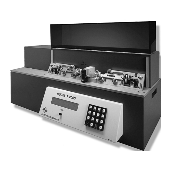
- Page 1 P-2000 Laser-Based Micropipette Puller System Operation Manual Rev. 2.4c ( 20160412) One Digital Drive Novato, CA 94949 Voice: 415-883-0128 Web: www.sutter.com Fax: 415-883-0572 Email: info@sutter.com...
- Page 2 Copyright © 2016 Sutter Instrument Company. All Rights Reserved. P-2000 MICROPIPETTE PULLER OPERATION MANUAL -– REV. 2.4C (20160412)
-
Page 5: Disclaimer
1:1997, and in most other countries by the relevant laser safety documents usually based on IEC60825-1:1997. The P-2000 Puller as manufactured is classified as a Class I laser product under each of the above mentioned laser safety standards. This means that it can be operated safely as shipped without the need for additional safety measures. -
Page 6: Safety Warning Labels
(Figure: Location of Laser Beam and "LASER ON" Warning Light.) SAFETY WARNING LABELS The following Safety labels are attached to the P-2000 when shipped to you: (Figure. Safety Labels on top of base plate.) (Figure: Safety Label on the bottom of the Base Plate.) -
Page 7: General Safety Warnings And Precautions
Electrical Operate the P-2000 using 110-120 V AC, 60 Hz, or 220-240 V AC., 50 Hz line voltage. This instrument is designed for connection to a standard laboratory power outlet (Overvoltage Category II), and because it is a microprocessor--controlled device, it should be accorded the same system wiring precautions as any 'computer type' system. -
Page 8: Back Injury Prevention
WARNING: To avoid injuring your back or limbs it is recommended that you do not attempt to lift this instrument by yourself. The P-2000 Micropipette Puller weighs in excess of 36.4 kg (over 80 lb) and should be moved by TWO (2) people and placed on a cart or trolley of sufficient robustness to support the weight. -
Page 9: Table Of Contents
3.4.3 Viewing a Program [NEXT] / [LAST]..................23 3.4.4 Clearing a Program from Memory [CLR] ................23 3.4.5 Editing a Program........................24 3.4.5.1 Entering a new program....................24 3.4.5.2 Editing an Existing Program ...................24 3.5 Software Control Functions......................25 P-2000 MICROPIPETTE PULLER OPERATION MANUAL -– REV. 2.4C (20160412) - Page 10 4.1 Pulling Very Short Micropipettes ....................43 4.2 Pulling Large-Diameter Glass .......................44 4.2.1 Background..........................44 4.2.2 Principles and Strategies......................44 4.2.3 Suggested Practices........................45 4.3 Determining Tip Concentricity .....................45 5. MAINTENANCE..........................49 5.1 Cleaning ............................49 5.1.1 Exterior .............................49 P-2000 MICROPIPETTE PULLER OPERATION MANUAL -– REV. 2.4C (20160412)
- Page 11 APPENDIX C. FUSE REPLACEMENT.....................65 APPENDIX D. TECHNICAL SPECIFICATIONS................67 TABLE OF FIGURES Figure 1-1. Information labels on the back of the P-2000 cabinet............2 Figure 1-2. Upper Cable Pulley Assembly ....................3 Figure 1-3. Puller Bar styles........................4 Figure 1-4. Retro Mirror Assembly......................5 Figure 1-5.
- Page 12 Figure 5-3. Micrometer scale........................51 Figure 5-4. Scanning mirror adjustment using thermal paper............52 Figure 5-5. Retro Mirror Adjustment....................53 Figure 5-6. Pulley adjustment.........................55 Figure 6-1. Power entry module ......................65 Figure 6-2. Fuse holder ........................... 65 P-2000 MICROPIPETTE PULLER OPERATION MANUAL -– REV. 2.4C (20160412)
- Page 13 Table 3-2. Standard factory configuration.....................21 Table 3-3. Default Programs........................22 Table 3-4. Control Functions........................25 Table 5-1. Pipette asymmetries and solutions..................54 Table 6-1. Fuse type and rating......................66 Table 6-2. Fuse type and rating......................67 P-2000 MICROPIPETTE PULLER OPERATION MANUAL -– REV. 2.4C (20160412)
- Page 14 (This page intentionally left blank.) P-2000 MICROPIPETTE PULLER OPERATION MANUAL -– REV. 2.4C (20160412)
-
Page 15: General Information
P-2000/G (up to 1.5 mm quartz and 1.8 mm conventional glasses) but the performance is best with glass that is 1.2 mm diameter or less. Model P-2000/F can also be used to pull tubing and optical fibers to exceedingly small diameters for research applications such as HPLC and near-field scanning microscopy, respectively. -
Page 16: Information Labels
Quartz (fused silica) tubing or fiber ranging from 0.125 mm to 0.6 mm (P-2000/F) or 0.6 mm to 1.2 - 1.8 mm in outer diameter (P-2000/G). Even though the P-2000/G Puller can handle glass with an outer diameter of up to 1.8 mm, the best performance is achieved with 1.2 mm or less. -
Page 17: Upper Cable Pulley Assembly
(H) holds the cable in a shallow groove (I) at the end of the puller bar, and forms the “resistance” against which the cable ends pull. See Figure 1-3 for the three different styles of puller bars found on P-2000/G and P- 2000/F Pullers. The “old-style” puller bars for model P-2000/G (Figure 1-3B) were discontinued in 2006. -
Page 18: Retro-Mirror Assembly
MICROMETER, SHROUD and COVER PLATE. The TWO-STAGE MICROMETER, SHROUD and COVER PLATE are discussed below. The RETRO MIRROR and use of the TWO-STAGE MICROMETER are detailed in the OPTICAL PATHWAY section of this chapter. P-2000 MICROPIPETTE PULLER OPERATION MANUAL -– REV. 2.4C (20160412) -
Page 19: Optical Pathway
Access holes in the side of the SHROUD allow the glass to be loaded into the optical pathway of the laser. On a fiber puller, model P-2000/F, the “fiber” SHROUD access holes are connected by a slot to make loading the fiber more convenient. -
Page 20: Figure 1-5. Optical Pathway (Top View Without Laser Housing)
NOTE: Although there are 16 different FILAMENT values, the latest version of the P-2000 firmware supports only six (0 through 5) different (unique) scanning patterns. The range of values 6 through 10 overlaps (duplicates) the last five of the first range (1 through 5), as does the last range (11 through 15). -
Page 21: Figure 1-6. Optical Pathway (Viewed From Right End Of Cabinet; Shroud, Laser And Laser Housing Not Shown)
This retro-reflective mirror or 'retro IRROR (Figure 1-6) mirror’ redirects the divergent laser radiation towards the front side of the glass and thereby provides relatively uniform heating around the circumference of the glass. P-2000 MICROPIPETTE PULLER OPERATION MANUAL -– REV. 2.4C (20160412) -
Page 22: Cabinet
The BASE includes the lower, blue cabinet to which the BASEPLATE is mounted as well as the transformers and the circuit board contained within. There are no user serviceable parts inside this cabinet. P-2000 MICROPIPETTE PULLER OPERATION MANUAL -– REV. 2.4C (20160412) -
Page 23: Installation
Box of sample glass Warranty registration The Model P-2000 is shipped to you in a prefabricated foam mold. Please take note of this method of packaging. Should it ever be necessary to ship the puller to another location the same method of packaging should be employed. Additional packing material may be purchased from Sutter Instrument. -
Page 24: Line Power (Mains)
6.3Appendix D Technical Specifications). Otherwise your protection from fire and electric shock may be compromised. Make certain that the Power Switch located on the left end of the P-2000 cabinet is turned OFF (see Figure 2-3). P-2000 MICROPIPETTE PULLER OPERATION MANUAL -– REV. 2.4C (20160412) -
Page 25: Figure 2-3. P-2000 Cabinet (End View, Left)
Figure 2-3. P-2000 Cabinet (end view, left) Plug the power cord provided with the P-2000 into the Line Input socket on the Power Entry Module and then to a power source of the appropriate voltage and frequency. Figure 2-4. Power connection... - Page 26 (This page intentionally left blank.) P-2000 MICROPIPETTE PULLER OPERATION MANUAL -– REV. 2.4C (20160412)
-
Page 27: Operations
1. Make certain that the shipping screw has been removed as described above. 2. Make certain that the P-2000 is plugged into the power outlet of the correct voltage and frequency. - Page 28 • If you are pulling a fiber on a P-2000/F Puller, you may want to load the fiber through the slot in the rather than inserting it sideways. All other steps are as described for glass capillaries.
-
Page 29: Front Panel
Used to move to the next line in a program while editing LAST Used to move to the previous line in a program while editing PULL Initiates the execution of a program STOP Aborts the execution of a program P-2000 MICROPIPETTE PULLER OPERATION MANUAL -– REV. 2.4C (20160412) -
Page 30: Display
3.2.2 Display The P-2000 has a four line Liquid Crystal Display. The following figure demonstrates what you will see after you have selected a program. A brief description of each parameter is provided below. Write Protection (Off) Last date/time edited SUTTER INSTRUMENT CO. -
Page 31: Figure 3-4. Lcd Display (Program Parameters)
3.3 Programs, 3.4 Pull Cycle and 3.7 Parameter Adjustment for more details. PULL Range: 0 to 255. The PULL parameter controls the force of the hard pull. See sections 3.3 Programs, 3.4 Pull Cycle and 3.7 Parameter Adjustment for more details. P-2000 MICROPIPETTE PULLER OPERATION MANUAL -– REV. 2.4C (20160412) -
Page 32: Programs
3.3 Programs 3.3.1 Program Structure The ultimate size and shape of a micropipette made using the P-2000 are determined by the parameter values that are programmed by the user. One hundred separate programs can be saved in positions 0 through 99 for future use. Each of those programs is structured as follows: Consists of one or more CYCLES (“Lines”) which, when executed in... -
Page 33: Table 3-1. Filament Scan Pattern Values
Range: 0 to 15. FILAMENT (FIL) specifies the scanning pattern of the laser ILAMENT beam that is used to supply HEAT to the glass. The P-2000 is preprogrammed with scanning pattern values (FILAMENTS), each of which defines the longitudinal length and the rate of the scan. The length of the region scanned is analogous to the width of the area heated by a conventional metal heating filament. -
Page 34: Pull Cycle
If DELAY is greater than HEAT turns off and hard PULL is activated after (DELAY-128) msec. If DELAY is less than 128 Hard PULL is activated and HEAT turns off after (128- DELAY) msec. P-2000 MICROPIPETTE PULLER OPERATION MANUAL -– REV. 2.4C (20160412) -
Page 35: Default Configuration
Damage to the instrument caused by inappropriate program parameters has not been reported. The following table shows the programs that have been installed at the factory: P-2000 MICROPIPETTE PULLER OPERATION MANUAL -– REV. 2.4C (20160412) -
Page 36: Selecting A Program [0 To 99]
COPYRIGHT SUTTER INSTRUMENT CORP. 1995 Figure 3-7. Power-on Display The P-2000 has the capacity to store 100 programs (0 - 99). On the keypad, press <0> and <ENTR> to call the factory installed micropipette program #0 (for thin wall, 1.0 mm quartz), or the number of another program you wish to execute. -
Page 37: Viewing A Program [Next] / [Last]
PROGRAM. If the cursor is on CYCLE 1, the entire program will be cleared from memory. If the cursor is on line 2, line 1 will be preserved, and lines 2-8 will be cleared. It does not P-2000 MICROPIPETTE PULLER OPERATION MANUAL -– REV. 2.4C (20160412) -
Page 38: Editing A Program
Adjustment. In general, inappropriate settings will only affect your ability to control the geometry of the glass micropipette you are trying to fabricate. Damage to the instrument caused by inappropriate program parameters has not been reported. P-2000 MICROPIPETTE PULLER OPERATION MANUAL -– REV. 2.4C (20160412) -
Page 39: Software Control Functions
HEAT values required to melt the glass with any given combination of FILAMENT and glass. With the P-2000, this significantly taxes the thermal resistance of the unit and reduces its operational lifetime. The RAMP TEST should only be run when troubleshooting or when instructed to do so by Sutter Technical Support personnel. -
Page 40: Write-Protect This Prog[Ram] <2
FUNCTIONS menu is displayed. The following message will then be displayed: NOTE: Although there are 16 different FILAMENT values, the current version of the P-2000 firmware supports only six (0 through 5) unique scanning patterns. The range of values 6 through 10 duplicates the last five of the first range (1 through 5), as does the last range (11 through 15). -
Page 41: Reset Time And Date <3
This CONTROL FUNCTION will perform a non-destructive test of the RAM. Press RESET to reset the system after performing this test. This option is chosen by pressing <4> when the CONTROL FUNCTIONS menu is displayed. The following message will then be displayed: P-2000 MICROPIPETTE PULLER OPERATION MANUAL -– REV. 2.4C (20160412) -
Page 42: Copy A Program <5
CHANGES ARE ALLOWED. Figure 3-18. Message indicating program is write-protected and therefore it cannot be changed. The status of write protection in the original program is copied along with the pull parameters. P-2000 MICROPIPETTE PULLER OPERATION MANUAL -– REV. 2.4C (20160412) -
Page 43: Pulling Pipettes
Parameter Adjustment section. 3.6.1.1 Looping A feature of the P-2000 is its capability to loop through a program. This is demonstrated with the multi-cycle Program 1, which is factory pre-programmed to pull a patch type pipette with a tip diameter of about 2 microns from 1.0mm x 0.5 mm Quartz glass. -
Page 44: Pull Results
4. If the puller detects that the glass still has not separated it will continue to line 2. If the glass does not separate after that pull the P-2000 will loop back to line 1 and continue as described above until the glass finally pulls apart. -
Page 45: Notes On Program Operation
(and with less detriment to the instrument’s circuitry) from the PULL RESULTS displayed on a P-2000 puller after each PULL. The HEAT ON value that is given there will change very little unless there has been a change in the type of glass being used (e.g., a thicker wall will increase the value) or there has been a change in the efficiency of... -
Page 46: Program Memory
4 to 6 seconds after the PULL key is pressed. If the pull takes longer than eight seconds, and you are trying to pull a fine P-2000 MICROPIPETTE PULLER OPERATION MANUAL -– REV. 2.4C (20160412) - Page 47 1 second after the programmed DELAY has elapsed. NOTE: Although there are 16 different FILAMENT values, the latest version of the P-2000 firmware supports only six (0 through 5) different (unique) scanning patterns. The range of values 6 through 10 overlaps (duplicates) the last five of the first range (1 through 5), as does the last range (11 through 15).
-
Page 48: Glass Selection
Glass larger than 1.0 mm can be difficult to pull with the P-2000 and is not advised. If it is necessary to use such glass, please refer to the chapter titled PULLING LARGE DIAMETER GLASS. -
Page 49: Sample Programs (For Quartz Glass)
HEAT 850 FIL 5 VEL 25 DEL 128 HEAT 700 FIL 4 VEL 50 DEL 130 PUL 150 P-2000 MICROPIPETTE PULLER OPERATION MANUAL -– REV. 2.4C (20160412) -
Page 50: Patch Pipette Fabrication
Delay Pull The P-2000 executes all programs line by line until either the glass separates or a blank line (zero for both VELOCITY and DELAY) is encountered. If the glass has not separated, the P- 2000 will loop back to the start and again execute line by line. This will continue until the glass separates. -
Page 51: Glass Selection
Larger diameter glass, particularly thin-walled quartz, NOTE: Although there are 16 different FILAMENT values, the latest version of the P-2000 firmware supports only six (0 through 5) different (unique) scanning patterns. The range of values 6 through 10 overlaps (duplicates) the last five of the first range (1 through 5), as does the last range (11 through 15). -
Page 52: Glass-Specific Parameter Adjustment
FLINT OR SOFT GLASS – These glasses generally are 1.5 to 1.8 mm in diameter, which is greater than the 1 mm diameter standard for the P-2000. If the glass can be loaded without rubbing on the holes in the enclosure, it may still be possible to use without adjustment of the puller. -
Page 53: Suggested Practices
Typically, these fibers are pulled from 0.125mm stock down to 40nm diameters. The small diameter and flexibility of the fiber stock requires the P-2000 to be configured specifically for the purpose of fiber optic probe (and electrospray tip) fabrication. -
Page 54: Electrospray/Nanospray Tip Fabrication
375 μm is shown below. The following text ( Selecting Program Parameters ) describes how the program parameters can be adjusted to give the desired tip geometry. P-2000 MICROPIPETTE PULLER OPERATION MANUAL -– REV. 2.4C (20160412) -
Page 55: Selecting Program Parameters
Drawing glass down to a tip while such a temperature gradient exists will cause the hotter outer layers of the glass to "slide" past the cooler inner layers. The result will P-2000 MICROPIPETTE PULLER OPERATION MANUAL -– REV. 2.4C (20160412) - Page 56 Using this approach, we developed the following program which produces very strong, stiff pipettes with a tip diameter under 15 nanometers from 1.0 mm outer diameter by 0.5 mm inner diameter quartz: Heat Filament Velocity Delay Pull P-2000 MICROPIPETTE PULLER OPERATION MANUAL -– REV. 2.4C (20160412)
-
Page 57: Applications And Techniques
4.1 Pulling Very Short Micropipettes The P-2000 can be used to pull pipettes with tapers as short as 2 mm in length from 1 mm X 0.5 mm quartz. With this same glass, it is also possible to make tips as small as 10 nanometers in diameter but with much longer tapers. -
Page 58: Pulling Large-Diameter Glass
In general, the more heating cycles the more rapid the taper but our experience with quartz on the P-2000 shows there seems to be little to gain in using more than two or three heating cycles. 4.2 Pulling Large-Diameter Glass 4.2.1 Background... -
Page 59: Suggested Practices
Mark the “top” and/or the “front” surface of the micropipette shaft (the “un-pulled” portion of the glass) with a pen (e.g., a “Sharpie”) before removing it from the puller bar clamp on P-2000 MICROPIPETTE PULLER OPERATION MANUAL -– REV. 2.4C (20160412) -
Page 60: Figure 4-1. Mounting The Pipette For Evaluation Of Its Geometry
P-2000. This mark will serve as a reference so that the orientation of any asymmetry in the pipette relative to the optical pathway of the laser beam can be determined. Figure 4-1. Mounting the pipette for evaluation of its geometry Remove the pipette from the puller and place the pipette orthogonally on the microscope stage plate (Figure 4-1) using a pipette holder or by using some sticky wax or clay. -
Page 61: Figure 4-2. Field Of View When Aligning The Pipette Shaft
Figure 4-3. Field of view when checking the concentricity It is important to roll the pipette 90° and then repeat the above test for asymmetric taper in that plane as well. P-2000 MICROPIPETTE PULLER OPERATION MANUAL -– REV. 2.4C (20160412) - Page 62 (This page intentionally blank.) P-2000 MICROPIPETTE PULLER OPERATION MANUAL -– REV. 2.4C (20160412)
-
Page 63: Maintenance
(G in Figure 5-1) occasionally to maintain reproducibility from pull to pull. Use a dry cotton swab to remove the dust and debris. CAUTION: DO NOT lubricate any components of the P-2000! No components on this unit require lubrication, and the application of lubricants to some of its parts can cause damage that will degrade the puller’s performance. -
Page 64: Optical Alignment
P-2000 from the factory. We recommend that you refrain from adjusting the mirrors until you have spoken with a member of the Sutter Instrument technical staff. In the event that you do need to adjust the mirrors, the following procedures can be used. -
Page 65: Reading The Micrometer
(see the instructions for cleaning the retro mirror). 2. For pulling 1.0 - 1.2 mm outer diameter glass on a P-2000/G, load a piece of 1.0mm OD tubing into the puller. For pulling small diameter fused silica capillary and optical fiber on a P-2000/F, load the small diameter fused silica capillary or the optical fiber that you will be using. -
Page 66: Retro-Reflective ("Retro") Mirror Adjustment
5.2.3 Retro-Reflective (“Retro”) Mirror Adjustment **CAUTION: Retro-mirror adjustments of any kind are extremely sensitive! Please contact Sutter Instrument Company P-2000 Tech Support before making any adjustments to the retro-mirror** The retro mirror is mounted on a two-stage manipulator allowing you to adjust the up/down (vertical) and in/out (horizontal) positions. -
Page 67: Figure 5-5. Retro Mirror Adjustment
Appendix B: Pulling glass accommodate glass larger than 1.2mm in diameter please see greater than 1 mm in diameter using the P-2000. Figure 5-5. Retro Mirror Adjustment To avoid accidental repositioning of the retro mirror the manipulator has been fitted with 3/16 nuts which require a nut driver or wrench to rotate. -
Page 68: Pulley Adjustment
(not shown) to the carriers (G in Figure 5-6A) is adjustable. While this is true, the performance of the P-2000 is EXTREMELY SENSITIVE to adjustments in this mechanism. To rule out other potential sources of this problem, this adjustment should not be made without first speaking with Sutter Technical Support Personnel. -
Page 69: Figure 5-6. Pulley Adjustment
If there is too much tension, the initial pull will depend on how tightly you hold the finger stops when the glass is clamped in the carriers. If this happens, the electrodes will not be consistent from pull to pull. P-2000 MICROPIPETTE PULLER OPERATION MANUAL -– REV. 2.4C (20160412) - Page 70 (This page intentionally left blank.) P-2000 MICROPIPETTE PULLER OPERATION MANUAL -– REV. 2.4C (20160412)
-
Page 71: Troubleshooting
VELOCITY value to be sure that you are in a stable region. The best procedure in developing a very reliable pipette program is to change P-2000 MICROPIPETTE PULLER OPERATION MANUAL -– REV. 2.4C (20160412) -
Page 72: Problem: One Electrode Is Much Longer Than The Other Electrode
If the display still shows a row of blocks, a failure in components that are not serviceable by the user has likely occurred. CONTACT SUTTER INSTRUMENT COMPANY TECHNICAL SUPPORT. P-2000 MICROPIPETTE PULLER OPERATION MANUAL -– REV. 2.4C (20160412) -
Page 73: Problem: Displayed Program Values Are Not Correct
Contact Sutter Instrument Company Technical Support. 6.3 Technical Support For further assistance, contact Sutter Instrument Technical Support at: (415) 883-0128 info@sutter.com P-2000 MICROPIPETTE PULLER OPERATION MANUAL -– REV. 2.4C (20160412) - Page 74 (This page intentionally blank.) P-2000 MICROPIPETTE PULLER OPERATION MANUAL -– REV. 2.4C (20160412)
-
Page 75: Appendix A. Limited Warranty
Warranty work will be performed only at the factory. The cost of shipment both ways is paid for by Sutter Instrument during the first three months this warranty is in effect, after which the cost is the responsibility of the customer. - Page 76 (This page intentionally blank.) P-2000 MICROPIPETTE PULLER OPERATION MANUAL -– REV. 2.4C (20160412)
-
Page 77: Appendix B. Accessories
Glass loading aid (GLA) . (Installs on either puller bar.) Pipette Storage Boxes Pipette storage box 4.75 x 3.625 x 0.75 inches. Pipette storage box 7 x 3.625 x 0.75 inches. P-2000 MICROPIPETTE PULLER OPERATION MANUAL -– REV. 2.4C (20160412) - Page 78 (This page intentionally blank.) P-2000 MICROPIPETTE PULLER OPERATION MANUAL -– REV. 2.4C (20160412)
-
Page 79: Appendix C. Fuse Replacement
Replace the active fuse with the spare and re-install the fuse holder and power cord. If the controller fails to power up with the new fuse installed, call Sutter Instrument technical support personnel for assistance. Figure 6-2. Fuse holder... -
Page 80: Table 6-1. Fuse Type And Rating
Bussmann: GMC-5A or S506-5-R (RoHS) (100 – 120 VAC) (Time Delay) Littelfuse: 239 005 (RoHS) “220” T3.15A, 250V Bussmann: GDC-3.15A or S506-3.15-R (RoHS) (200 – 240 VAC) Littelfuse: 218 3.15 (RoHS) P-2000 MICROPIPETTE PULLER OPERATION MANUAL -– REV. 2.4C (20160412) -
Page 81: Appendix D. Technical Specifications
Orange line 3.2A, 250V, 3AG A41-80-36 transformer (All Type T (slow blow)) Yellow #1 line 3.2A, 250V, 3AG Yellow #2 line 3.2A, 250V, 3AG Power cord 10A, 250V, with safety ground plug P-2000 MICROPIPETTE PULLER OPERATION MANUAL -– REV. 2.4C (20160412) - Page 82 (This page intentionally left blank.) P-2000 MICROPIPETTE PULLER OPERATION MANUAL -– REV. 2.4C (20160412)
- Page 83 69 default configuration..........29 defaults configuration............. 21 General Information ..........1 programs............21 Introduction ............1 delay glass selection............34 definition ............. 17, 20 glassware determining tip concentricity......47 loading ............... 13 P-2000 MICROPIPETTE PULLER OPERATION MANUAL -– REV. 2.4C (20160412)
- Page 84 75, 76 mains ..............10 fuses ..............v, 69 power cord ............69 operation..............29 voltage..............69 first time use ............. 13 maintenance precautions............vi cleaning optical alignment ..........52 exterior............51 optical fiber P-2000 MICROPIPETTE PULLER OPERATION MANUAL -– REV. 2.4C (20160412)
- Page 85 23 glass............43 program info line ..........23 technical tips ............. 43 programs parameter adjustment.......... 32 default..............21 general information.......... 32 Programs ............... 18 P-2000 MICROPIPETTE PULLER OPERATION MANUAL -– REV. 2.4C (20160412)
- Page 86 ......45 controlling pipette tip shapes ......59 Technical Support ..........61 ramp test ............... 25 two-stage manipulator ..........5 reset................ 15 retro mirror..............7 alignment ............54 unpacking..............9 cleaning.............. 51 P-2000 MICROPIPETTE PULLER OPERATION MANUAL -– REV. 2.4C (20160412)
- Page 87 V-bearings ..............4 W/WP..............16 velocity warranty..............63 definition ............. 17, 19 write protection..........16, 26 voltage mains..............69 voltage selector switch ......... 10 NOTES P-2000 MICROPIPETTE PULLER OPERATION MANUAL -– REV. 2.4C (20160412)
- Page 88 NOTES P-2000 MICROPIPETTE PULLER OPERATION MANUAL -– REV. 2.4C (20160412)
Need help?
Do you have a question about the P-2000 and is the answer not in the manual?
Questions and answers