Table of Contents

Related Manuals for Sutter Instrument Lambda DG-4


Summary of Contents for Sutter Instrument Lambda DG-4
- Page 1 Lambda DG-4 Lambda DG-5 Ultra-High-Speed Wavelength Switching Illumination System Operation Manual Rev. 3.05c ( 20150414) One Digital Drive Novato, CA 94949 Voice: 415-883-0128 Web: www.sutter.com Fax: 415-883-0572 Email: info@sutter.com...
- Page 2 Copyright © 2015 Sutter Instrument Company. All Rights Reserved. LAMBDA-10 ® and SmartShutter ® are registered trademarks of Sutter Instrument Company. LAMBDA DG-4 & DG-5 OPERATION MANUAL – REV. 3.05C (20150414)
-
Page 5: Disclaimer
SAFETY WARNINGS AND PRECAUTIONS Electrical Operate the Lambda DG-4/5 using 110-120 V AC, 60 Hz, or 220-240 V AC., 50 Hz line voltage. This instrument is designed for connection to a standard laboratory power outlet (Overvoltage Category II), and because it is a microprocessor--controlled device, it should be accorded the same system wiring precautions as any 'computer type' system. -
Page 6: Avoiding Electrical Shock And Fire-Related Injury
INFRARED RADIATION: The infrared radiation (and ultraviolet radiation) generated by this lamp can cause significant skin burns and eye damage. THE SMARTSHUTTER IS NOT A SAFETY SHUTTER: The Lambda DG-4 Smart and DG-5 can be optionally equipped with a Sutter Instrument Shutter. -
Page 7: Avoiding Physical Injury And Equipment Damage While Replacing The Xenon Bulb
WARNING: Before removing the xenon arc lamp bulb housing assembly from a Lambda LS or Lambda DG-4/5 system, make certain that the system is powered down (single switch for the Lambda LS or both MAIN and LAMP switches for the Lambda DG-4/5) and disconnect the power cord from the source. - Page 8 V. HOT SURFACES - Portions of the lamp can reach temperatures of several hundred degrees centigrade and cause serious burns if touched even after the lamp is turned off. LAMBDA DG-4 & DG-5 OPERATION MANUAL – REV. 3.05C (20150414)
-
Page 10: Table Of Contents
3.4 Top Panel Controls .........................14 3.4.1 Keypad............................14 3.5 Electrical Connections........................15 3.5.1 Parallel Port..........................16 3.5.2 Serial Port ..........................16 3.5.3 Filter Value Out ........................16 3.5.4 Sync............................17 3.5.5 DAC............................17 3.5.6 Strobe............................17 3.5.7 Line Power ..........................17 LAMBDA DG-4 & DG-5 OPERATION MANUAL – REV. 3.05C (20150414) - Page 11 4.1.2 Input Lines..........................36 4.1.3 Command Codes........................36 4.1.4 Busy Line ..........................40 4.1.5 Interface Modes ........................41 4.1.6 Controlling the Lambda DG-4/5 from a Computer’s Parallel (Printer) Port....41 4.1.7 Reading the Status of the Lambda DG-4/5 ................43 4.1.8 Shutter Control ........................45 4.2 Serial Interface..........................45 4.2.1 Connecting to the Lambda DG-4/5 Serial Input..............45...
- Page 12 Figure 4-3. Serial control connections (viewed from rear of cabinet)..........46 Figure 5-1. Lamp bulb assembly components..................51 Figure 5-2. Lamp cover panel on left side of the Lambda DG-4/5-series cabinet......52 Figure 5-3. Heat sink retaining-clip removal..................53 Figure 5-4. Bulb surfaces requiring they be covered with thermal compound........54 Figure 5-5.
- Page 13 Listing 4-1. A routine for obtaining the status of the DG-4/5.............. 44 Listing 4-2. Command echo check routine.....................47 Listing 4-3. Command-completion check routine.................47 Listing 4-4. Reading the Lambda DG-4/5's status.................48 LAMBDA DG-4 & DG-5 OPERATION MANUAL – REV. 3.05C (20150414)
-
Page 15: General Information
1. GENERAL INFORMATION 1.1 Introduction The Lambda DG-4 and Lambda DG-5 are two models of an illumination system that is designed for the rapid change of wavelength. The system comprises three subsystems: controller, optical path, and lamp light source with power supply. All three subsystems are conveniently housed in one cabinet. -
Page 16: Figure 1-1. Lambda Dg-4/5 Optical Pathway
Lambda DG-4/5 can be used as a source of white light when required. The optical path subsystem in the Lambda DG-4/5 is arranged so that 2 mirrors, each mounted on a fast closed-loop servoed galvanometer, can route the collimated output of the lamp through one of 4 or 5 optical paths (e.g., filter position 1 in the diagram below). -
Page 17: Lambda Dg-4 And Lambda Dg-5
Throughout this manual, unless otherwise noted, all references and descriptions pertaining to “Lambda DG-4” (or just “DG-4”) apply equally to the Lambda DG-5. The only difference between the Lambda DG-4 and Lambda DG-5 is the set of light interference filter holders, as follows: The Lambda DG-4 filter set consists of four 25mm (1-inch) diameter filter holders. - Page 18 (This page intentionally blank.) LAMBDA DG-4 & DG-5 OPERATION MANUAL – REV. 3.05C (20150414)
-
Page 19: Installation
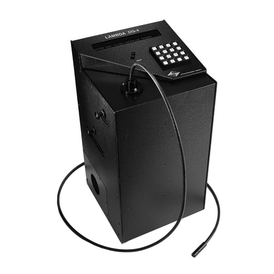
(110 or 220). Do not turn on the power, yet. 2. Insert either end of the light guide into the port on the top panel of the Lambda DG-4/5 cabinet (see below) and tighten the thumbscrew to hold it in place. The top of the light guide end sleeve should be flush with the top surface of the port fitting (see below). -
Page 20: Figure 2-2. Lambda Dg-4/5 Left Side
DO NOT LOOK DIRECTLY INTO THE LIGHT GUIDE! 4. A hose should be connected to the 4” fitting on the back of the Lambda DG-4/5 cabinet to ventilate the ozone from the xenon lamp to the environment or to an ozone removal device. - Page 21 (with minimal attenuation), respectively. Now that you have completed the “Make it Glow” section of the manual, you should be familiar with the basic components and operation of the Lambda DG-4/5. To get set up for an experimental application you will need to: Install the LIGHT GUIDE into the OPTICAL HOLDER (if not already in place).
-
Page 22: Light Guide & Optical Holder Installation
Program the desired FILTER NUMBERS. Establish the desired interface between the Lambda DG-4/5 and your computer. Each of these steps is discussed in the following sections of the manual. 2.3 Light Guide & Optical Holder Installation 2.3.1 Liquid Light Guide The light output of the Lambda 10 DG4 is focused onto one end of a liquid light guide. -
Page 23: Loading Filters
Remember, the light path inside the Lambda DG-4/5 travels from BOTTOM TO TOP . Therefore, the filters should be oriented with their “Lamp Side”... -
Page 24: Selection Of A Filter Position
. Filter installation is the same for this filter holder as described above. The slide portion of the neutral density filter holder, however, is mechanically different from those used for the interference filters. As a result, the two types of holders may not be interchanged. LAMBDA DG-4 & DG-5 OPERATION MANUAL – REV. 3.05C (20150414) -
Page 25: Filter Holder Installation
FILTER HOLDERS. The small access door located near the top edge of the left side panel on the Lambda DG-4/5 cabinet (see below) is for the neutral-density FILTER HOLDER. The larger door in the middle of the left side panel is fro the interference FILTER HOLDER. - Page 26 (This page intentionally blank.) LAMBDA DG-4 & DG-5 OPERATION MANUAL – REV. 3.05C (20150414)
-
Page 27: Operations
The intensity and wavelengths of the light that can be produced by the Lambda DG-4/5 are such that it should not be turned on unless the light is directed into a microscope and away from the eyes or skin of the operator or other nearby personnel. -
Page 28: Top Panel Controls
3.4.1 Keypad Figure 3-1. Keypad (top panel). There are 16 keys on the Lambda DG-4/5 keypad. The numerical keys 0 to 9 and six function keys. Keys are read while depressed but the appropriate action will occur only when the key is released. -
Page 29: Electrical Connections
LOCAL Pressing this key puts the unit under LOCAL control. This is the only key that has an effect when the Lambda DG-4/5 is ON LINE (i.e., under the remote control of an interfaced external source, such as a computer. -
Page 30: Parallel Port
NUMBER in use. Pin numbers 1 through 4 correspond to the bit number of the 4-bit binary equivalent of the decimal FILTER NUMBER value. Pin 5 carries the BUSY line signal and pins 6 through 8 are tied to ground. LAMBDA DG-4 & DG-5 OPERATION MANUAL – REV. 3.05C (20150414) -
Page 31: Sync
The default mode (“MOVE ON COMMAND”) allows you to directly command filter changes (e.g., using the numeric keys on the keypad when the Lambda DG-4/5 is under LOCAL (“Manual”) control). Filter changes can also be controlled using an external trigger (“MOVE ON STROBE PULSE”), video synchronization pulse (“MOVE ON SYNC PULSE”) or a... -
Page 32: Selecting An Operational Mode: The Mode Key
(“MOVE ON SYNC PULSE, INHIBITED BY THE STROBE LINE”). By default, the Lambda DG-4/5 will be in the MOVE ON COMMAND mode when it starts up, and at any time after a “triggered” mode has been inactivated. The active operational mode (of these four) will be indicated on the right side of the bottom line in the MAIN MENU. -
Page 33: Move On Command Mode
NUMBER (8 in this case). Method 1: The main menu would look like this if the initial FILTER NUMBER = 10 10 = FILTER NUMBER, TURBO-BLANKING- OFF INPUT = MANUAL MOVE ON COMMAND LAMBDA DG-4 & DG-5 OPERATION MANUAL – REV. 3.05C (20150414) -
Page 34: Move On Sync Pulse Mode
(sync) circuit detects the vertical sync pulse of a composite video signal applied to the SYNC input on the rear of the Lambda DG-4/5. In this way, filter changes can be coordinated to occur with the capture of video “frames”. The FILTER NUMBER sequence can be programmed at your convenience and then executed later with precise timing (see SET UP THE RING BUFFER). -
Page 35: Move On Strobe Pulse Mode
3 = DISPLAY THE FIRST 4 FILTER VALUES Press 1 for the NEXT PAGE to see the desired option or press the 0 key to abort the routine and return to the MAIN MENU. LAMBDA DG-4 & DG-5 OPERATION MANUAL – REV. 3.05C (20150414) -
Page 36: Move On Sync, Inhibited By The Strobe Line Mode
The computer interfaced with the Lambda DG-4/5 must be set up to monitor the video signal and hold the STROBE line HIGH if the number of frames to be captured with each FILTER NUMBER is to be constant. -
Page 37: Edit A Filter Definition Mode
[MODE/7] 3.7.7.1 General Information The optical pathway for light from the xenon lamp in the Lambda DG-4/5 is determined by the angle at which the mirrors on the Input and Output galvanometers are positioned. The Input Galvanometer directs the collimated light beam through one of the four FILTER POSITIONS (shown below) and, thus, through whatever interference filter is installed there. -
Page 38: Filter Numbers
3500 3.7.7.2 Filter Numbers The Lambda DG-4/5 uses paired Input and Output Galvanometer Values to define a given optical pathway. Any pair of Galvanometer Values can be assigned a FILTER NUMBER from 1-15. It is important to remember that a FILTER NUMBER is a “logical filter” and does not necessarily correspond to the number on the cabinet that labels the FILTER POSITION through which that optical pathway passes. -
Page 39: Attenuation
1 log unit. It is recommended that you use neutral density filters when attenuation of 1 log unit or more is desired. Figure 3-6. Log of attenuation vs. change in output galvanometer value. LAMBDA DG-4 & DG-5 OPERATION MANUAL – REV. 3.05C (20150414) -
Page 40: Programming A Filter Number ("Logical Filter")
It is recommended that these assignments be retained but there is no overwrite protection. If you do edit these values, the original values can be found on the Optical Alignment Data Sheet that came with your Lambda DG-4/5. Galvanometer Values, which maximally misalign the Input and Output Galvanometers, have been assigned FILTER NUMBER 0. -
Page 41: Manual Adjustment Of Attenuation
FILTER NO. = 4 , OLD INPUT VALUE = ENTER NEW INPUT GALVO. VALUE At this prompt, enter the desired Input Galvanometer Value. The Lambda DG-4/5 will expect to have four digits entered. If fewer are entered you must complete the entry by pressing the ENTER key. -
Page 42: Setup Ring Buffer Mode
64 FILTER NUMBER values into the RING BUFFER but the additional 32 values are stored in a volatile memory and will be lost if the Lambda DG-4/5 is turned off or RESET. LAMBDA DG-4 & DG-5 OPERATION MANUAL – REV. 3.05C (20150414) -
Page 43: Storing The Filter Number Sequence
0=EXIT. 1 = RUN EXISTING BUFFER, 2 = TO CREATE NEW FILTER SEQUENCE. 3 = DISPLAY Press 2 to begin recording a new sequence of FILTER NUMBERS. The following prompt will briefly appear: LAMBDA DG-4 & DG-5 OPERATION MANUAL – REV. 3.05C (20150414) -
Page 44: Viewing An Existing Filter Number Sequence
Press 8 to view the SETUP RING BUFFER menu or the 0 key to return to the MAIN MENU. The following display will appear if you press 8: 0=EXIT. 1 = RUN EXISTING BUFFER, 2 = TO CREATE NEW FILTER SEQUENCE. 3 = DISPLAY LAMBDA DG-4 & DG-5 OPERATION MANUAL – REV. 3.05C (20150414) -
Page 45: Running The Ring Buffer Sequence
“triggered” mode before proceeding and that the trigger source is connected to the appropriate input on the back of the Lambda DG-4/5. To “manually” RUN the RING BUFFER access the SETUP RING BUFFER menu by pressing the MODE key followed by the 8 key. -
Page 46: Turbo-Blanking Mode
This operational mode is selected by pressing the MODE key. The following menu will be displayed: 0=EXIT, 1=NEXT PAGE, 2 = TURBO BLANKING 3 = DISPLAY THE FIRST 4 FILTER VALUES To display the TURBO-BLANKING menu shown below, press 2. LAMBDA DG-4 & DG-5 OPERATION MANUAL – REV. 3.05C (20150414) -
Page 47: Display The First Four Filter Values Mode
3 = DISPLAY THE FIRST 4 FILTER VALUES To bring up the values display, press 3. #1 IN=3800 OUT=1000 #2 IN=2500 OUT=2100 #3 IN=1500 OUT=3200 #4 IN=1000 OUT=4000 Press ANY key to return to the MAIN MENU. LAMBDA DG-4 & DG-5 OPERATION MANUAL – REV. 3.05C (20150414) - Page 48 (This page intentionally blank.) LAMBDA DG-4 & DG-5 OPERATION MANUAL – REV. 3.05C (20150414)
-
Page 49: External Control Operations
4. EXTERNAL CONTROL OPERATIONS The Lambda DG-4/5 has both serial and parallel interfaces but these two interfaces should not be connected simultaneously. The parallel port provides you with the fastest remote interface possible. The serial port connection provides you with a similar range of commands but at a significantly slower speed. -
Page 50: Input Lines
See the BUSY LINE section for further details about this data line. 4.1.3 Command Codes All commands to the Lambda DG-4/5 correspond to an 8-bit binary value (not all of the possible 256 values are utilized). The binary values that are used can be classified in the following way: Table 4-2. -
Page 51: Table 4-3. Dg-4-Only Filter Position Movement Commands
NOTE: “Move on Command” means move the light beam immediately upon receipt of the external command. “Move on Trigger” means move the light beam only until triggered via Strobe, Synch, or Synch gated to Strobe. LAMBDA DG-4 & DG-5 OPERATION MANUAL – REV. 3.05C (20150414) -
Page 52: Table 4-4. Dg-5-Only Filter Position Movement Commands
NOTE: “Move on Command” means the light beam is moved to the specified position immediately upon receipt of the external command. “Move on Trigger” means move the light beam only until triggered via Strobe, Synch, or Synch gated to Strobe. LAMBDA DG-4 & DG-5 OPERATION MANUAL – REV. 3.05C (20150414) -
Page 53: Table 4-5. Controller Commands
Stops up-dating of the display in order to allow the highest frequency of filter changes 11011010 Turn Display ON Restores normal updating of the display (the opposite of the Freeze Display (218) command). 11011011 LAMBDA DG-4 & DG-5 OPERATION MANUAL – REV. 3.05C (20150414) -
Page 54: Busy Line
11110010 4.1.4 Busy Line The Lambda DG-4/5 parallel interface has only one output line, BUSY. The first response of the unit to a new command is to set the BUSY output line HIGH. The BUSY line will stay HIGH until the control unit is ready to accept new data.. -
Page 55: Interface Modes
The details of the input and output signals were described previously. Now we will discuss the way in which these signals may be used to control the Lambda DG-4/5 from a PC compatible computer’s parallel port. This information is provided as a limited example and is only intended to show the elements useful in controlling the Lambda DG-4/5. -
Page 56: Figure 4-2. Db25 Parallel Connector
Command Bit 4 Data Bit 5 Command Bit 5 Data Bit 6 Command Bit 6 Data Bit 7 Command Bit 7 BUSY BUSY LINE OUTPUT SELECT AUTOFEED ERROR INIT SELECT IN LAMBDA DG-4 & DG-5 OPERATION MANUAL – REV. 3.05C (20150414) -
Page 57: Reading The Status Of The Lambda Dg-4/5
4.1.7 Reading the Status of the Lambda DG-4/5 The BUSY line is the only output from the Lambda DG-4/5. In the BUSY line section (above), there is a discussion of some of the factors to consider in deciding whether to read the BUSY signal at all. - Page 58 BUSY signal. With the Lambda DG-4/5 BUSY line connected to PIN 11 of the computer’s parallel printer port the input port can be read to obtain the status of the Lambda DG-4/5. Using Microsoft QuickBasic, this would be done as follows: Listing 4-1.
-
Page 59: Shutter Control
4.2 Serial Interface 4.2.1 Connecting to the Lambda DG-4/5 Serial Input RS-232 serial control of the Lambda DG-4/5 is provided through a 9-pin connector on the rear of the controller cabinet. Only the ground and the two data lines are connected: the hardware control lines are not connected. -
Page 60: Controlling The Lambda Dg-4/5 From A Computer's Serial Port
The option list “CD0,CS0,DS0” causes Basic to ignore the DCD, CTS and DSR control lines. In order to send commands to the Lambda DG-4/5 via the serial port, you must first place the Lambda DG-4/5 in the serial mode. If the Lambda DG-4/5 is in either the parallel or manual mode it can be placed in the serial mode by simply sending the decimal value 238 (EE hexadecimal) via the serial port. -
Page 61: Serial Port Command Echo
COMMANDCHECK: IF LOC(1) > 0 THEN SerialInput$ = INPUT$(1, #1) IF DATANUM = ASC(SerialInput$) THEN RETURN GOTO COMMANDCHECK NOTE: The only serial command not echoed back by the Lambda DG-4/5 is the “Go On Line” (238 decimal, EE hexadecimal) command. 4.2.4 Serial Port Command Completion Indicator... -
Page 62: Listing 4-4. Reading The Lambda Dg-4/5'S Status
DATANUM = 238 ‘FORCE ON-LINE FOR CHANNEL THAT RECEIVED IT DATANUM = 240 ‘END LOADING RING BUFFER FILTERS DATANUM = 241 ‘RUN RING BUFFER (FIRST SELECT TRIGGER SOURCE) DATANUM = 242 ‘END RING BUFFER RUN LAMBDA DG-4 & DG-5 OPERATION MANUAL – REV. 3.05C (20150414) - Page 63 LAMBDA DG-4 & DG-5 OPERATION MANUAL – REV. 3.05C (20150414)
-
Page 65: Maintenance
3. Front terminal (smaller threads) 4. Rear terminal (larger threads) 5. Front (thinner) heat sink 6. Bulb mounting ring 7. Xenon Bulb 8. Rear (thicker) heat sink 9. Heat sink retaining clips LAMBDA DG-4 & DG-5 OPERATION MANUAL – REV. 3.05C (20150414) -
Page 66: Removing The Lamp Assembly From The System
3. Grasp the top and bottom handles of the blue plastic housing assembly and, carefully, pull the assembly straight out of the cabinet. Figure 5-2. Lamp cover panel on left side of the Lambda DG-4/5-series cabinet. LAMBDA DG-4 & DG-5 OPERATION MANUAL – REV. 3.05C (20150414) -
Page 67: Bulb Replacement
If they still slide, remove the retaining rings, tighten them using a vice or adjustable pliers, and then reaffix them on to the heat sinks. LAMBDA DG-4 & DG-5 OPERATION MANUAL – REV. 3.05C (20150414) -
Page 68: Figure 5-4. Bulb Surfaces Requiring They Be Covered With Thermal Compound
Screw in the terminals (the one located closer to the sapphire window has smaller threads than the other) slightly more than hand tight to complete the bulb installation in the blue housing. LAMBDA DG-4 & DG-5 OPERATION MANUAL – REV. 3.05C (20150414) -
Page 69: Reinstalling The Lamp/Housing Assembly To The System
8. Reaffix the black cover panel and screw it in place with the four knurled screws. 9. Screw in the five screws at the lower left corner of the left side panel where the lamp access door is located. LAMBDA DG-4 & DG-5 OPERATION MANUAL – REV. 3.05C (20150414) - Page 70 (This page intentionally blank.) LAMBDA DG-4 & DG-5 OPERATION MANUAL – REV. 3.05C (20150414)
-
Page 71: Appendix A. Limited Warranty
Warranty work will be performed only at the factory. The cost of shipment both ways is paid for by Sutter Instrument during the first three months this warranty is in effect, after which the cost is the responsibility of the customer. - Page 72 (This page intentionally blank.) LAMBDA DG-4 & DG-5 OPERATION MANUAL – REV. 3.05C (20150414)
-
Page 73: Appendix B. Accessories
WARNING: Full-spectrum bulbs produce ozone, which is toxic and must be eliminated from the area in which the Lambda DG-4/5 operates. Please be certain that you have proper ventilation – systems installed with full-spectrum bulbs must be connected to an ozone- removing device or system. -
Page 74: 18Mm Interference Filter Accessories
Dedicated SmartShutter controller system, with serial and USB interface cables, power cord, and manual. NOTE: For a full list of available accessories for the Lambda DG-4 and DG-5, refer to the Products section of Sutter Instrument’s web site ( http://www.sutter.com... -
Page 75: Appendix C. Fuse Replacement
5mm x 20mm. Specific fuse ratings depend on the power of the xenon lamp used in the Lambda DG-4/5, as indicated in the following tables. LAMBDA DG-4 & DG-5 OPERATION MANUAL – REV. 3.05C (20150414) -
Page 76: Tablec-1. Mains Fuse Requirements According To Lamp Power Ratings And Line Voltage
Littelfuse: 218 3.15P Littelfuse: 218 3.15 5.0A, Bussmann: GMC-5-R Bussmann: GMC-5A Watts 125V Littelfuse: 239 005 Littelfuse: 239 005.P NOTE: The 125-Watt lamp version of the DG-4/DG-5 is a discontinued product. LAMBDA DG-4 & DG-5 OPERATION MANUAL – REV. 3.05C (20150414) -
Page 77: Appendix D. Technical Specifications
48 x 25 x 25 cm (19 x 10 x 10 in) Weight: 20 kg (45 lb) Light Guide: Core Type Liquid Length 2 m (6.5 ft) Diameter 3 mm (0.11 in) LAMBDA DG-4 & DG-5 OPERATION MANUAL – REV. 3.05C (20150414) -
Page 78: Table D-1. Cable Specifications
Pin 1 of the other, Pin 2 to Pin 2, etc.). Do not substitute the provided cable with a “null-modem” cable, or any cable that has Pins 2 and 3 crossed and/or connected to other non-corresponding pins. LAMBDA DG-4 & DG-5 OPERATION MANUAL – REV. 3.05C (20150414) -
Page 79: Appendix E. External-Control Command Reference
Move on Command or Trigger (Bit 4): 0 (on command (i.e., immediately) or 1 (by trigger (see Note 3)). “On trigger” means the light beam moves only on Strobe (strobe line), Synch (video synch), or Synch Gated by Strobe. LAMBDA DG-4 & DG-5 OPERATION MANUAL – REV. 3.05C (20150414) -
Page 80: Table E-2. Filter Selection Command Structure
Selects triggered by video sync gated by strobe line as the ring 11001110 Alt-0206 buffer mode Deselects triggered by video sync gated by strobe line as the ring 11001111 Alt-0207 buffer mode LAMBDA DG-4 & DG-5 OPERATION MANUAL – REV. 3.05C (20150414) - Page 81 Therefore, this part of the table is left blank – if you wish, you may write in the characters defined in the character set you use on a regular basis. LAMBDA DG-4 & DG-5 OPERATION MANUAL – REV. 3.05C (20150414)
- Page 82 (This page intentionally blank.) LAMBDA DG-4 & DG-5 OPERATION MANUAL – REV. 3.05C (20150414)
-
Page 83: Index
35 ENTER.............. 15 F1,F2..............15 LOCAL............... 15 filter MODE............15, 18 cup.................9 numeric.............. 15 cup spacer ring.............9 ON LINE............15 loading ..............9 manual switching ..........7 orientation............9 light guide LAMBDA DG-4 & DG-5 OPERATION MANUAL – REV. 3.05C (20150414) - Page 84 ........... 16, 35 life..............61 control..............41 output range..........61 input lines............36 type..............61 pin assignment..........35 lamp ..............61 power light guide connection ............17 dimensions............. 61 LAMBDA DG-4 & DG-5 OPERATION MANUAL – REV. 3.05C (20150414)
- Page 85 ..........14 connection ............6 trigger video synchronization ........20, 22 connection ............17 connection ............17 TURBO-BLANKING........10, 32 warranty..............55 unpacking..............5 weight ..............61 NOTES LAMBDA DG-4 & DG-5 OPERATION MANUAL – REV. 3.05C (20150414)
- Page 86 NOTES LAMBDA DG-4 & DG-5 OPERATION MANUAL – REV. 3.05C (20150414)
Need help?
Do you have a question about the Lambda DG-4 and is the answer not in the manual?
Questions and answers