
Subscribe to Our Youtube Channel
Related Manuals for JDS Uniphase Wavetek DSAM-3500B


Summary of Contents for JDS Uniphase Wavetek DSAM-3500B
- Page 1 JDSU DSAM-3500B Specs Provided by www.AAATesters.com DSAM Product Family Series Wavetek™ Series Field Meter Quick-Start Guide...
- Page 3 DSAM Product Family Series Wavetek™ Series Field Meter Quick-Start Guide...
- Page 5 Trademarks JDS Uniphase, JDSU, and DSAM are trademarks or regis- tered trademarks of JDS Uniphase Corporation in the United States and/or other countries. Specifications, terms, and conditions are subject to change without notice.
- Page 6 WEEE JDSU has established processes in compliance with the Waste Electrical and Electronic Equipment (WEEE) Direc- Directive tive, 2002/96/EC. Compliance This product should not be disposed of as unsorted munic- ipal waste and should be collected separately and disposed of according to your national regulations. In the European Union, all equipment purchased from JDSU after 2005-08-13 can be returned for disposal at the end of its useful life.
-
Page 7: Table Of Contents
Table of Contents About This Guide ..........viii Purpose and Scope ............viii Assumptions ..........viii Technical Assistance ............. ix Conventions Chapter 1 Safety Instructions ........2 Important Safety Instructions ............2 Meter Safety ............3 Battery Safety ......5 Battery Power Supply Module Safety Chapter 2 DSAM Meter Operation ............8... - Page 8 Table of Contents ........12 Connecting the RF Cable .......12 Making Additional Connections ..........13 Powering the Meter ........13 Selecting a Power Option ............13 Battery Care ..........14 Charging the Battery .........14 Interpreting the Battery LED’s ........16 Charging Temperature Range ............16 Using the Keypad ..........18 Using the mode keys ........19...
- Page 9 Table of Contents ......47 Displaying the Access Files Menu ........48 Managing Files and Folders ........48 Synchronizing Your Data ......48 Displaying the Access Browser Menu .......49 DSAM Firmware Upgrade Instructions ..........52 Cloning DSAM Meters ..........53 Replacing the Lens Appendix A Specifications ......56 DSAM Product Family Specifications ......64...
- Page 10 Table of Contents DSAM Product Family Quick-Start Guide Rev. 001...
- Page 11 About This Guide This chapter describes how to use this guide. Topics discussed in this chapter include the following: – “Purpose and Scope” on page viii – “Assumptions” on page viii – “Technical Assistance” on page viii – “Conventions” on page ix DSAM Product Family Quick-Start Guide Rev.
-
Page 12: About This Guide
About This Guide Purpose and Scope Purpose and Scope The purpose of this guide is to help you successfully use the DSAM meter features and capabilities. This guide includes task-based instructions that describe how to use and obtain support for the DSAM meter. Addi- tionally, this guide provides a description of JDSU’s warranty. -
Page 13: Conventions
About This Guide Conventions Table 1 Technical Assistance Centers (Continued) Region Phone Number Europe, +49 (0) 7121 86 1345 hotline.europe@jdsu.com Africa, and (Europe) Mid-East +800 882 85822 support.uk@jdsu.com (European Freephone) +49 (0) 6172 59 11 00 hotline.germany@jdsu.com (JDSU Germany) +33 (0) 1 39 30 24 24 hotline.germany@jdsu.com (JDSU France) Asia Pacific... - Page 14 About This Guide Conventions Table 2 Typographical Conventions Description Example User interface actions appear in On the Status bar, click Start. this typeface. Buttons or switches that you press Press the switch. Typeface on a unit appear in this Code and output messages appear All results okay in this typeface.
- Page 15 About This Guide Conventions Table 4 Symbol Conventions This symbol represents a general hazard. This symbol represents a risk of electrical shock. NOTE This symbol represents a Note indicating related infor- mation or tip. Table 5 Safety Definitions WARNING Indicates a potentially hazardous situation which, if not avoided, could result in death or serious injury.
- Page 16 About This Guide Conventions DSAM Product Family Quick-Start Guide Rev. 001...
-
Page 17: Safety Instructions
Safety Instructions Chapter 1 This chapter describes DSAM meter Safety Instructions. The topics discussed in this chapter are as follows: – “Important Safety Instructions” on page 2 DSAM Product Family Quick-Start Guide Rev. 001... -
Page 18: Important Safety Instructions
Chapter 1 Safety Instructions Important Safety Instructions Important Safety Instructions Follow these safety precautions to reduce the risk of fire, shock, or personal injury and to avoid damage to the DSAM meter and its power components. 1 Read all instructions in this section regarding the meter, battery and universal power supply. -
Page 19: Battery Safety
Chapter 1 Safety Instructions Important Safety Instructions WARNING Do not disassemble the meter. Do not attempt to service this product yourself. There are no user-serviceable parts inside. Contact the appro- priate JDSU representative for meter repair or calibra- tion. Battery Safety Follow these safety precautions to reduce the risk of fire, shock, or personal injury and to avoid damage to the DSAM battery:... - Page 20 Chapter 1 Safety Instructions Important Safety Instructions 7 Operate and store the battery only within the following ranges: Li-Ion – Charging 0 to +45° C (+32° to +113° F) – Discharge -20° to +60° C (-4° to +140° F) – Short term storage (30 days or less) -20°...
-
Page 21: Battery Power Supply Module Safety
Chapter 1 Safety Instructions Important Safety Instructions Battery Power Follow these safety precautions to reduce the risk of fire, shock, or personal injury and to avoid damage to the Supply Module DSAM power supply module: Safety 1 When powering the meter, maintain the secure connection of each power component. - Page 22 Chapter 1 Safety Instructions Important Safety Instructions DSAM Product Family Quick-Start Guide Rev. 001...
-
Page 23: Dsam Meter Operation
DSAM Meter Operation Chapter 2 This chapter describes the functionality of the DSAM meter. Topics discussed in this chapter are as follows: – “Product Overview” on page 8 – “Initial Set-Up” on page 9 – “Powering the Meter” on page 13 –... -
Page 24: Product Overview
Chapter 2 DSAM Meter Operation Product Overview Product Overview The DSAM Product Family provides a combination of DOCSIS®/EuroDOCSIS® cable modem installation meters for the on-site installation and service of high- speed data and video services. Using exclusive digital signal processing and integrated DOCSIS®/EuroDOCSIS®... -
Page 25: Initial Set-Up
Chapter 2 DSAM Meter Operation Initial Set-Up sources for additional technical assistance, the product warranty, equipment return instructions, and specifications for the meter and its power components. Initial Set-Up Typically your DSAM meter is shipped with the following accessories: – One (1) Hi-Capacity Li-Ion rechargeable battery –... -
Page 26: Removing The Battery
Chapter 2 DSAM Meter Operation Initial Set-Up Removing the To remove the battery Battery 1 Ensure the power is off. CAUTION INSTRUMENT DAMAGE Failure to turn the power off before removing the batter- ies from the DSAM meter could damage internal com- ponents and/or corrupt the software. -
Page 27: Battery To External Power Connection
Chapter 2 DSAM Meter Operation Initial Set-Up Battery to External Power Connection IMPORTANT Read all safety instructions in the front of this guide before attempting to power the meter or charge the bat- tery (see “Important Safety Instructions” on page Connect the external power components to the DSAM battery as follows: (Figure 2 on page... -
Page 28: Connecting The Rf Cable
Chapter 2 DSAM Meter Operation Initial Set-Up Figure 2 External Power Components Connecting To conduct measurements with your DSAM meter, connect the RF cable of the system you are servicing to the RF Cable the RF connection port on the back panel of the meter. Making Use the Ethernet port located on the top of the meter to clone settings with other DSAM meters (see... -
Page 29: Powering The Meter
Chapter 2 DSAM Meter Operation Powering the Meter Powering the Meter IMPORTANT Read all safety instructions in the front of this guide before attempting to power the meter or charge the bat- tery (see “Important Safety Instructions” on page Selecting a There are three ways to provide power to your DSAM meter. -
Page 30: Charging The Battery
Chapter 2 DSAM Meter Operation Powering the Meter Charging the With the power components properly connected (see “External Power Components” on page 12) the DSAM Battery battery can be charged when outside of the meter or when installed in the meter. NOTE You can power the DSAM meter and recharge the bat- teries at the same time. - Page 31 Chapter 2 DSAM Meter Operation Powering the Meter Charge 12 Volt Indicator DC Port LEDS Figure 3 DSAM Battery The green “OK” LED illuminates to indicate that the battery is completely charged. The red “CHARGE” LED illuminates to indicate the present charge condition.
-
Page 32: Charging Temperature Range
Chapter 2 DSAM Meter Operation Using the Keypad Charging Your DSAM charger module will not allow the charge mode to begin if the battery temperature is not within a Temperature safe range for charging. To begin and maintain the charge Range mode, the battery temperature should be approximately between 0°... - Page 33 Chapter 2 DSAM Meter Operation Using the Keypad Display Screen Display Softkeys Exit key Enter key Arrow Mode keys keys Alphanumeric keys Shift key Power key Figure 4 DSAM Meter Front Panel The keypad is comprised of: – Four Display Softkeys (directly below the display screen) used to select screen-specific options or to select pop-up menus associated with each key –...
-
Page 34: Using The Mode Keys
Chapter 2 DSAM Meter Operation Using the Keypad – An Enter key used to select highlighted menu items and input alphanumeric data – An Exit key used to depart from the currently viewed screen to a previously viewed option – Four Mode keys (Figure 5) used to access the meter’s four primary functional modes... -
Page 35: Using The Display Softkeys
Chapter 2 DSAM Meter Operation Using the Keypad Using the Display Softkeys (directly below the display screen) are used to select screen-specific options or to select pop-up Display menus associated with each key. Softkeys Figure 6, the softkey below Limits was pressed to access the Limits pop-up menu in Level Mode. - Page 36 Chapter 2 DSAM Meter Operation Using the Keypad For example, press the Shift key and then press the number 5 key to access the “?” shortcut – which takes you directly to the Help system (“?” means “Help”). The Help system has more information about each shortcut feature.
-
Page 37: Custom Shortcuts
Chapter 2 DSAM Meter Operation Using the Keypad Table 7 Shift Key Shortcuts Key Sequence Icon Description Shift, 6 Displays Meter Info screen. Shift,7 Displays Configure Adjust Contrast screen. Shift,8 Pause (used in some measurement modes). Shift,9 Automatically adjust the analog meter to the best reference setting. - Page 38 Chapter 2 DSAM Meter Operation Using the Keypad Figure 9 Custom Shortcut Configuration Figure 10 Custom Shortcuts Displayed After Pressing “Shift” Key DSAM Product Family Quick-Start Guide Rev. 001...
-
Page 39: Using The Help System
Chapter 2 DSAM Meter Operation Using the Help System Using the Help System Your DSAM meter is equipped with an on-board Help system designed to answer many of the questions you may have about the proper configuration of the meter and the purpose and use of its measurement functions. - Page 40 Chapter 2 DSAM Meter Operation Configuring the Meter Figure 11 Configure Mode General Menu Configure modes are indicated by softkey tabs at the bottom of the display screen – General, Measure, Channel Plan, and Access. Each configuration mode has a menu of configurable items specific to that mode. To access a Configure Mode menu, press the softkey directly below the mode you wish to view.
-
Page 41: General Configuration
Chapter 2 DSAM Meter Operation Configuring the Meter General To view the Configure General menu, press the General Configuration softkey when in Configure mode. Use general configuration to: – adjust sounds – optimize battery life – enter your personal information –... -
Page 42: Measurement Configuration
Chapter 2 DSAM Meter Operation Configuring the Meter Measurement To view the Configure Measure menu (Figure 12 on Configuration page 26), press the Configure mode key (Figure 5 on page 18), then press the Measure softkey. Figure 12 Configure Mode Measure Menu Use measure configuration to specify: –... - Page 43 Chapter 2 DSAM Meter Operation Configuring the Meter parameters (characteristics) of individual channels can be edited within a plan to meet a variety of measurement objectives. To view the Configure Channel menu (Figure 13), press the Configure mode key (Figure 5 on page 18), then press the Channel Plan softkey.
-
Page 44: Access Configuration
Chapter 2 DSAM Meter Operation Configuring the Meter Access To view the Configure Access menu (Figure 14), press the Configuration Configure mode key (Figure 5 on page 18), then press the Access softkey. Figure 14 Configure Mode Access Menu Use pc connection to select your preferred PC connection (Ethernet or RF) to TPP or FDM and to define its IP address. -
Page 45: Using Measure Mode
Chapter 2 DSAM Meter Operation Using Measure Mode Using Measure Mode Measurement modes are indicated by softkey tabs at the bottom of the display screen – Basic, Service, Spectrum and Sweep. Each measurement mode has a menu of measurement items specific to that mode. To access a Measure Mode menu, press the softkey directly below the mode you wish to view. -
Page 46: Service Menu
Chapter 2 DSAM Meter Operation Using Measure Mode Figure 15 Measure Mode Basic Menu Service Menu To view the Measure Service menu (Figure 16 on page 30), press the Measure mode key (Figure 5 on page 18), then press the Service softkey. Use the arrow keys to highlight the type of measurement you wish to perform and press Enter to access that option. -
Page 47: Spectrum Menu
Chapter 2 DSAM Meter Operation Using Measure Mode Spectrum Menu To view the Measure Spectrum menu (Figure 17), press the Measure mode key (Figure 5 on page 18), then press the Spectrum softkey. Use the arrow keys to highlight the type of measurement you wish to perform and press Enter to access that option. -
Page 48: Performing Signal Level Measurements
Chapter 2 DSAM Meter Operation Using Measure Mode Figure 18 Measure Mode Sweep Menu Performing Level measurement mode views and analyzes the signal level of each carrier within a channel (as defined by the Signal level active channel plan). Measurements To access Level mode, use the arrow keys to highlight the Level option on the Measure mode menu (Figure 15 on... -
Page 49: Performing Miniscan Measurements
Chapter 2 DSAM Meter Operation Using Measure Mode Figure 19 Level Mode Screen To configure the Level measurement feature, select the channel plan to be tested and the tuning mode you prefer. If desired, you can select a set of measurement limits and the parameters of those limit sets. -
Page 50: Performing Spectrum Measurements
Chapter 2 DSAM Meter Operation Using Measure Mode Figure 20 Miniscan Mode Screen To configure the Miniscan measurement feature, select: the channel plan to be tested, up to twelve channels for Miniscan measurement, a set of measurement limits (based on test location), the parameters of those limit sets, and the resolution of the Miniscan graph for the best viewing. -
Page 51: Performing Docsis ® Measurements
Chapter 2 DSAM Meter Operation Using Measure Mode Figure 21 Upstream Spectrum Mode Screen To configure Upstream Spectrum Mode, select the measurement limit option (or turn it off), and (if it is on) set an appropriate pass/fail limit value for your installation. Position the marker at each frequency to display the level value. - Page 52 Chapter 2 DSAM Meter Operation Using Measure Mode primary DOCSIS® channels should be configured in the channel plan, but they will not show up in the list of DOCSIS® channels. To access DOCSIS® Mode, use the arrow keys to high- light the DOCSIS®...
- Page 53 Chapter 2 DSAM Meter Operation Using Measure Mode – If necessary, edit the parameters of the limit set you have selected. Figure 23 Select DOCSIS® Version that the Meter Should Emulate Figure 24 Select DOCSIS® Test Parameters DSAM Product Family Quick-Start Guide Rev. 001...
- Page 54 Chapter 2 DSAM Meter Operation Using Measure Mode Figure 25 Test in Progress Figure 26 DOCSIS® 3.0 Summary Results DSAM Product Family Quick-Start Guide Rev. 001...
-
Page 55: Performing Dqi Measurements
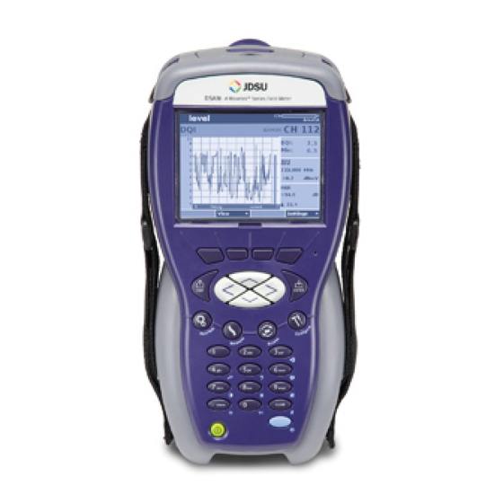
Chapter 2 DSAM Meter Operation Using Measure Mode – Figure 27 DOCSIS® 3.0 Throughput Performing The measurement Digital Quality Index (DQI) is a real- time measurement that immediately detects intermittent issues and some sustained issues within a downstream Measurements QAM stream. In comparison, the typical measurement used to check for these issues on a digital QAM carrier is the pre and post forward error correction (FEC) bit error rate (BER). -
Page 56: Using Autotests Mode
Chapter 2 DSAM Meter Operation Using AutoTests Mode Figure 28 DQI Mode Screen The DQI display shows three minutes of data. Figure 28 displays a point where over a minute passed before DQI dropped to a point where BER might capture the issue. Using AutoTests Mode One AutoTest measurement mode is indicated by the softkey tab at the bottom of the display screen –... - Page 57 Chapter 2 DSAM Meter Operation Using AutoTests Mode – Video Channels AutoTest - user-configured level measurements of a series of analog and/or digital video channels, – Home Certification - (optional purchase required) is a user configured combination of tests. The tests can be any combination of testing on video channels and DOCSIS®...
-
Page 58: Using Combo Autotest
Chapter 2 DSAM Meter Operation Using AutoTests Mode Figure 29 AutoTests Menu You are ready to perform tests in AutoTest mode only when: – The meter is receiving power – The RF cable is connected to the meter (on the back panel) –... -
Page 59: Using Video Channels Autotest
Chapter 2 DSAM Meter Operation Using AutoTests Mode Figure 30 Combo Autotest Mode Screen Each Combo AutoTest is based on two types of configura- tion: – The parameters or the selected channel plan – The parameters of the selected limit plan After a channel plan and a limit set has been selected, press the Start softkey and Combo AutoTest measures the signal performance of all assigned channels in the... -
Page 60: Using Home Certification Autotest
Chapter 2 DSAM Meter Operation Using AutoTests Mode Figure 31 Video Autotest Mode Screen Each Video AutoTest is based on two types of configura- tion: – The parameters or the selected channel plan – The parameters of the selected limit plan After a channel plan and a limit set has been selected, press the Start softkey (Figure... -
Page 61: Using Proof Of Performance
Chapter 2 DSAM Meter Operation Using AutoTests Mode Figure 32 Home Certification Autotest Mode Screen Each Home Certification AutoTest is based on three types of configuration: – The parameters or the selected channel plan – The parameters of the selected limit plan –... -
Page 62: Using Cable Modem Autotest
Chapter 2 DSAM Meter Operation Using AutoTests Mode Figure 33 Proof of Performance Autotest Mode Screen Each Proof of Performance AutoTest is based on four types of configuration: – The selection of channels to be tested – The parameters of your limit sets –... -
Page 63: Using Access Mode
Chapter 2 DSAM Meter Operation Using Access Mode Figure 34 Cable Modem Autotest Mode Screen Each Cable Modem AutoTest is based on two types of configuration: – The parameters or the selected channel plan – The parameters of the selected limit plan After a channel plan and a limit set has been selected, press the Start softkey and Cable Modem AutoTest measures the signal performance of all assigned channels... -
Page 64: Managing Files And Folders
Chapter 2 DSAM Meter Operation Using Access Mode Figure 35 Access Files Menu Managing Files Use the Work Folders feature to create a new folder for and Folders your measurement files, rename or examine the proper- ties of an existing folder, delete a folder that you no longer need, or delete (purge) all folders that have been synchro- nized with optional TPP and FDM utility software. -
Page 65: Dsam Firmware Upgrade Instructions
Chapter 2 DSAM Meter Operation DSAM Firmware Upgrade Instructions Figure 36 Access Browser Menu Use Access Browser menu to select: – WFA Browser - used to save, send, and receive various applications and system information – Local Browser - used to open a saved Browser page –... - Page 66 Chapter 2 DSAM Meter Operation DSAM Firmware Upgrade Instructions If you are using FDM-100, visit the FDM-100 Upgrade page here. To maximize upgrade reliability, please upgrade your DSAM on networks that have reliable connections, minimal network congestion, and no restricting firewalls. In the case where you feel you may have such IP or RF networks or have experienced upgrade failures, we recommend that a direct laptop connection or Ethernet...
- Page 67 Chapter 2 DSAM Meter Operation DSAM Firmware Upgrade Instructions Ensure that the DSAM(s) you are upgrading appear in the Meter Assets list, specified by serial number. If they are not on the list, you must add the DSAM(s) and synchronize them before you proceed to the next step.
-
Page 68: Cloning Dsam Meters
Chapter 2 DSAM Meter Operation Cloning DSAM Meters If you have any issues after re-trying to synchronize, please contact TAC at the number below. – 1-866-228-3762- United States – +1 317-614-8051 - Worldwide E-mail CATV TAC at catvsupport@jdsu.com Cloning DSAM Meters Use the Clone feature to transfer DSAM settings from or to this meter. -
Page 69: Replacing The Lens
Chapter 2 DSAM Meter Operation Replacing the Lens Figure 37 Configure General Clone Screen Use an Ethernet crossover cable or a standard Ethernet cable with a crossover adapter to connect the DSAM meters. The Ethernet port is on the top of the meter. Replacing the Lens Your DSAM meter is shipped with one replaceable lens (optional lens can be purchased) covering the display... - Page 70 Chapter 2 DSAM Meter Operation Replacing the Lens To replace a lens 1 Gently insert your fingernail or a small coin into the thin rectangular notch centered directly below the display screen and push forward (not down) until the installed lens begins to bend at the sides in the shape of a small arc.
-
Page 71: Appendix A Specifications
Specifications Appendix A This appendix describes the DSAM meter requirements. Topics discussed in this appendix are as follows: – “DSAM Product Family Specifications” on page 56 – “Power Component Specifications” on page 64 DSAM Product Family Quick-Start Guide Rev. 001... -
Page 72: Dsam Product Family Specifications
Appendix A Specifications DSAM Product Family Specifications DSAM Product Family Specifications Table 8 Product Specifications Item Description Frequency Range 4 to 1,000 MHz Accuracy ±10 ppm at 25° C (77° F) Tuning Resolution Analog 10 kHz Digital 50 kHz Channel Bandwidth Supports 6 or 8 MHz depending on channel type Analog Level Measurement... - Page 73 Appendix A Specifications DSAM Product Family Specifications Table 8 Product Specifications (Continued) Item Description Digital Level Measurement Modulation Types QPR, QPSK, QAM (DVB/ACTS) Range -40 to +50 dBmV (typical) Resolution 0.1 dB Accuracy ± 2.0 dB typical at 25° C (77° F) Two-way Ranging Test DOCSIS®...
- Page 74 Appendix A Specifications DSAM Product Family Specifications Table 8 Product Specifications (Continued) Item Description Downstream QAM Demodulation Modulation Type 64, 128 , and 256 QAM, ITU-T J.83 Annex A, B, or C (selectable) Input Range (Lock Range) -15 to +50 dBmV total integrated power from: 57-1000 MHz (42 MHz Diplexer 6 MHz Channel spacing)
- Page 75 Appendix A Specifications DSAM Product Family Specifications Table 8 Product Specifications (Continued) Item Description EVM (Error Vector Range 64 QAM: 0.4% to 5.8% Magnitude) magnitude Accuracy: ± 0.5% (0.9% to 2.0%) ± 1.0% (2.1% to 4.0%) ± 1.4% (4.1% to 5.8%) Range 128/256 QAM: 0.4% to 2.4% Accuracy: ±...
- Page 76 Appendix A Specifications DSAM Product Family Specifications Table 8 Product Specifications (Continued) Item Description Downstream Spectrum (forward scan) (optional) Frequency range 4 to 1000 MHz Sweep rate Less than 2.5 seconds (display) Display scaling and range 1, 2, 5 and 10 dB/division; 6 vertical divisions Resolution bandwidth 30 or 280 kHz...
- Page 77 Appendix A Specifications DSAM Product Family Specifications Table 8 Product Specifications (Continued) Item Description DSAM Sweep Specifications (optional) Forward Sweep Requires SDA-5500 (SDA compatible mode) Reverse Sweep and Reverse Requires SDA-5500 (Single Reverse) Alignment or SDA-5510 (Multiple Reverse) (SDA compatible mode) Sweep Modes Frequency Range 5 to 1000 MHz Forward...
- Page 78 Appendix A Specifications DSAM Product Family Specifications Table 8 Product Specifications (Continued) Item Description Interfaces 75 ohm, F81 or BNC option Maximum Sustained Volt- 100V AC and 140V DC RS232 via optional direct cable Ethernet RJ45, 10/100/1000 base T, TCP/IP, and UDP supported v1.1 host mode, 150 mA maximum slave...
- Page 79 Appendix A Specifications DSAM Product Family Specifications Table 8 Product Specifications (Continued) Item Description Dimensions (without QAM 12 cm (W) 25 cm (H) 10.8 cm (D) Ingress option) 4.75" (W) 9.75" (H) 4.25" (D) (with battery) Dimensions (with QAM Ingress 12 cm (W) 25 cm (H) 12.1 cm (D) option) 4.75"...
-
Page 80: Power Component Specifications
Appendix A Specifications Power Component Specifications Power Component Specifications Table 9 Power Component Specifications Item Description Environmental Operational temperature range -20° to +50° C (-4° to +122° F) Storage temperature range -20° to +60° C (-4° to +140° F) Short Term (30 days or less) High fast-charge inhibit range 55°... -
Page 81: Appendix B Customer Services
Customer Services Appendix B This chapter describes the customer services available through JDSU. Topics discussed in this chapter include the following: – “About Our Services” on page 66 – “Customer Care” on page 66 DSAM Product Family Quick-Start Guide Rev. 001... -
Page 82: About Our Services
Appendix B Customer Services About Our Services About Our Services JDSU offers an unmatched portfolio of services to deploy, support and innovate purchased equipment through its Customer Care and Global Services and Solutions organi- zations. Customer Care is standard with every product sale and consists of business hour technical assistance, in-warranty repair, calibration, and upgrade services. -
Page 83: Equipment Return Instructions
Appendix B Customer Services Customer Care Equipment Please contact your local Customer Care location via tele- phone or web site for Return or Reference Authorization to Return accompany your equipment. For each piece of equipment Instructions returned for repair, attach a tag that includes the following information: –... - Page 84 Appendix B Customer Services Customer Care ship, material or not in compliance with the JDSU specifi- cation applicable to the Product and has in fact failed under normal use on or before: (i) for Software, ninety (90) days from the Delivery Date of the Software; and (ii) for all other Products one (1) year from the Delivery Date of the Product, unless otherwise stated in writing by JDSU.
- Page 85 Appendix B Customer Services Customer Care erly installed or otherwise abused or is used in hazardous activities; or (viii) acts of God or other Force Majeure conditions. Excluded Product and Components. Customer has no warranty rights with regard to any (i) consumable Product or parts thereof (e.g., parts with an expected useful life of less than ninety (90) days, such as certain batteries);...
- Page 86 Appendix B Customer Services Customer Care licenses to any Firmware shall be automatically revoked. Customer hereby transfers to JDSU title and ownership of any parts that JDSU replaces. Disclaimer. THE REMEDIES EXPRESSLY PROVIDED IN THIS SECTION WILL BE CUSTOMER'S SOLE AND EXCLUSIVE REMEDIES AND SHALL BE IN LIEU OF ANY OTHER RIGHTS OR REMEDIES CUSTOMER MAY HAVE AGAINST JDSU WITH RESPECT TO ANY NON-...
- Page 88 Test and Measurement Regional Sales North America Latin America Asia Pacific EMEA www.jdsu.com Toll Free: 1 800 638 2049 Tel: +55 11 5503 3800 Tel: +852 2892 0990 Tel: +49 7121 86 2222 Tel: +1 240 404 2999 Fax:+55 11 5505 1598 Fax:+852 2892 0770 Fax:+49 7121 86 1222 Fax:+1 240 404 2195...
Need help?
Do you have a question about the Wavetek DSAM-3500B and is the answer not in the manual?
Questions and answers