Table of Contents
Advertisement
Quick Links
Advertisement
Table of Contents

Subscribe to Our Youtube Channel
Related Manuals for JDS Uniphase BACKREFLECTION METER RM3750


Summary of Contents for JDS Uniphase BACKREFLECTION METER RM3750
- Page 1 You~ Artisan Scientific is Source for: Quality New and Certified-Used/Pre:-awned ECJuiflment • Tens of Thousands of In-Stock Items • Hundreds of Manufacturers Supported Service Center Repairs Experienced Engineers and Technicians on staff in our State-of-the-art Full-Service In-House Service Center Facility We bUy used equipment! We also offer credit for Buy-Backs and Trade-Ins Sell your excess.
- Page 2 RM3 SERIES BACKREFLECTION METER USER’S MANUAL RM3 SERIES BACKREFLECTION METER User’s Manual 10112341 Rev 002 Page 1 of 39 Artisan Scientific - Quality Instrumentation ... Guaranteed | (888) 88-SOURCE | www.artisan-scientific.com...
-
Page 3: Table Of Contents
Temperature ...19 Humidity...19 Voltage ...19 Storing and Shipping...19 Claims and Repackaging...19 Returning Shipments to JDS Uniphase ...19 Cleaning Connectors...20 Powering Up the Meter...21 Operating and Maintenance Instructions ...22 10112341 Rev 002 Artisan Scientific - Quality Instrumentation ... Guaranteed | (888) 88-SOURCE | www.artisan-scientific.com RM3 SERIES BACKREFLECTION METER USER’S MANUAL... - Page 4 Programming Examples ...40 RS232 Interface Program Example ...40 Customized Features and Test Data...41 For sales and service information, contact JDS Uniphase or your local representative. JDS Uniphase Corporation E-mail: instruments@jdsuniphase.com 10112341 Rev 002 Artisan Scientific - Quality Instrumentation ... Guaranteed | (888) 88-SOURCE | www.artisan-scientific.com...
-
Page 5: Safety Information, Instructions, And Symbols
Website: http://www.jdsuniphase.com Safety Information, Instructions, and Symbols Safety Information Classification The RM Series Backreflection Meter consists of an exposed metal chassis that is connected directly to earth via a power cord and, therefore, is classified as a Class 1 instrument. Disconnecting from Line Power Some of the circuits are powered whenever the unit is connected to the AC power source (line power). - Page 6 RM3 SERIES BACKREFLECTION METER USER’S MANUAL Under the laser classification of the US Food and Drug Administration (FDA) Center for Devices and Radiological Health (CDRH), the laser contained in the unit is a Class 1 laser. CLASS 1 LASER PRODUCT 10112341 Rev 002 Page 5 of 39 Artisan Scientific - Quality Instrumentation ...
-
Page 7: Safety Instructions
Failure to comply with any of these instructions or with any precaution or warning contained in the user’s manual is in direct violation of the standards of design, manufacture, and intended use of the unit. JDS Uniphase assumes no liability for the customer’s failure to comply with any of these safety requirements. - Page 8 not use repaired fuses, and avoid any situations that can short-circuit the fuse. Unless absolutely necessary, do not attempt to adjust or perform any maintenance or repair procedure when the unit is opened and connected to a power source. Repairs are to be carried out only by a JDSU qualified technician. Do not attempt any adjustment, maintenance, or repair procedure to the unit’s internal mechanism if immediate first aid is not accessible.
-
Page 9: Safety Symbols
Safety Symbols The following symbols and messages can be marked on the unit (Table 2). Observe all safety instructions that are associated with a symbol. Table 2: Safety Symbols Symbol Laser safety. See the user’s manual for instructions on handling and operating the unit safely. -
Page 10: Compliance
RM3 SERIES BACKREFLECTION METER USER’S MANUAL Compliance CE Compliance The unit has been designed and tested to comply with directive 73/23/EEC and its subsequent amendments by the European Community (EC or CE). The directive relates to electrical equipment designed for use within certain voltage limits. It ensures that electrical equipment is constructed with good engineering practice in safety matters. - Page 11 RM3 SERIES BACKREFLECTION METER USER’S MANUAL non-conductive pollution occurs. Occasionally, however, a temporary conductivity caused by condensation must be expected.” 10112341 Rev 002 Page 10 of 39 Artisan Scientific - Quality Instrumentation ... Guaranteed | (888) 88-SOURCE | www.artisan-scientific.com...
-
Page 12: General Information And Specifications
RM3 SERIES BACKREFLECTION METER USER’S MANUAL General Information and Specifications General Information This user’s manual for the RM3 Series Backreflection Meter contains complete operating instructions. The RM meter can be ordered as a single-mode or multimode model. Software is bundled with the meter; for information on using the software, see the Multiple Connector Test System Software User’s Manual (document SD000318). -
Page 13: Backreflection Measurements
Backreflection Measurements Reflections in optical systems can come from a number of sources. Primary sources include the fiber (Rayleigh backscatter) and Fresnel reflections that occur at the planar junction of two materials having different refractive indices, for example, connector and fiber endfaces, splices, bulk optic interfaces, and detector surfaces. -
Page 14: Output Port
Output Port The output port of the RM meter is equipped with an ultra-low backreflection APC connector. To prevent damage to the output port connector, a measurement jumper must be used for all measurements, even for measuring a component with an APC connector. Internal Light Sources The RM meter can be equipped with two internal laser sources. -
Page 15: Applications
User-calibration mode RS232 serial and IEEE 488 GPIB parallel interface Convenient data logging via serial port to a computer or serial printer Direct display of measured backreflection, power, or insertion loss Applications Connector backreflection and loss testing Component testing Installation verification Quality assurance (QA) acceptance testing Standard Accessories AC power cord (country specific) -
Page 16: Specifications
Specifications The following optical specifications describe the warranted characteristics of the unit ( Table 3). Supplementary specifications describe the typical non-warranted performance of the unit (Table 4). Table 3: Optical Specifications Parameter Operating wavelength 980, 1310, 1480, 1550, 1625, or 1650 ±10 nm Fiber Type 9 / 1 2 5 µ... - Page 17 RM3 SERIES BACKREFLECTION METER USER’S MANUAL Flexcor is a trademark of Corning 10112341 Rev 002 Page 16 of 39 Artisan Scientific - Quality Instrumentation ... Guaranteed | (888) 88-SOURCE | www.artisan-scientific.com...
- Page 18 Table 4: Other Specifications Electrical Input voltage 100 to 240 V AC, 50 to 60 Hz Power consumption 25 VA maximum Physical Display 16-character LCD Dimensions (W x H x D) 26 x 11 x 26 cm Weight 4 kg Environmental Operating temperature 0 to 40 °C...
-
Page 19: Getting Started
Read the user’s manual thoroughly, and become familiar with all safety symbols and instructions to ensure that the unit is operated and maintained safely. If the unit is used in a manner not specified by JDS Uniphase, the protection provided by the unit may be impaired. -
Page 20: Operating Environment
The unit or any of its components are damaged or defective The unit does not pass the initial inspection In the event of carrier responsibility, JDS Uniphase will allow for the repair or replacement of the unit while a claim against the carrier is being processed. -
Page 21: Cleaning Connectors
invoice number, and an itemized statement of claimed defects must be included with the return material. Ship return material in the original shipping container and packing material. If these are not available, packaging guidelines are as follows: 1. Cover the front panel with foam to prevent damage. 2. -
Page 22: Powering Up The Meter
1. Blow the sleeve with filtered compressed air (Figure 2). Figure 2: Connector Cleaning (connector type can vary) 2. Apply optical grade isopropyl alcohol or optical grade ethanol (do not use rubbing alcohol) to a small area of a lint-free towel and rub the end of the ferrule over the wet area. 3. -
Page 23: Operating And Maintenance Instructions
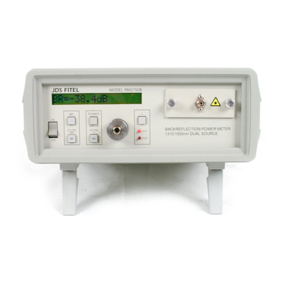
Operating and Maintenance Instructions Front Panel The front of the meter (model RM3750) is shown in Figure 3 and described inTable 5. Not all RM3 Series meters are exactly as shown. Table 5: Front Panel Operating Keys and LEDs Key/LED ON / OFF Power on ON / OFF switch. -
Page 24: Rear Panel
Rear Panel The back of the meter (Figure 4) can vary with the model. The components on the rear panel are described in Table 6. Table 6: Rear Panel Components Component Access to the User CAL value, for calibration purposes. Foot pedal jack for data logging. -
Page 25: Termination Techniques For Single-Mode (980 Nm) And Multimode Fiber
need to be made just before the high-attenuation bends in order to offset the small amount of reflection caused by the high-attenuation bends. 1. Using the size of rod specified in the Inspection Report (see the Customized Features and Test Data section), wind the cable around the rod until the reading displayed on the RM meter no longer changes (approximately six turns). -
Page 26: Backreflection Measurements
Figure 5b: Terminating the Jumper for BR Measurement for Single-mode (980 nm only) and 3. The second termination is made after the DUT in order to obtain Br Figure 6b: Measuring Backreflection for Single-mode (980 nm only) and Multimode Backreflection Measurements Setting Up the Meter for Backreflection Measurements To prepare the meter for backreflection measurements: 1. -
Page 27: Measuring Backreflection
6. Terminate the measurement jumper just before the output connector, and hold the termination point steady (figure 5a for single-mode(except 980nm), and figure 5b for single- mode(980nm) and multimode). NOTE The termination technique is different depending on the type of the RM Meter used : single-mode (except 980 nm), single-mode (980nm) or multimode. -
Page 28: Backreflection Accuracy And Range
temperature. To ensure accurate backreflection measurements below -65 dB (-25 dB for multimode): 1. Perform the BR measurement at least once per shift. The measured backreflection is affected by losses that can occur between the meter and the DUT. To compensate for these losses, measure the total amount of loss between the output of the measurement hybrid jumper and the input of the DUT (see the Loss and Power Measurements section). -
Page 29: Measuring Power
5. Attach the appropriate detector adapter to the detector on the front of the meter. 6. Connect the output connector of the measurement jumper to the detector adapter. This end of the measurement jumper is user-selected and must be compatible with the input connector of the DUT. -
Page 30: Measuring Relative Power (Insertion Loss)
4. Connect the output connector of the DUT to the detector on the front of the meter. The detector must be equipped with the appropriate detector adapter. The RM meter displays the DUT absolute power output (Figure 8). 5. If a measurement is to be made at a second wavelength, repeat steps 2 to 4. Figure 8: Measuring Absolute Power Measuring Relative Power (Insertion Loss) The value for relative power is the negative value of the insertion loss, for example -31 dB... -
Page 31: Power Accuracy
Figure 9: Measuring Relative Power Power Accuracy The absolute accuracy of power measurements made with the RM meter is dependent on the power level to be measured. The RM meter does not measure power levels below -50 dBm unless the dark signal from extraneous sources ( To ensure accurate power measurements below -65 dBm, store The value of can change with temperature fluctuations. -
Page 32: Calibrating The Meter
Devices with malfunctioning lasers must be returned to the manufacturer for calibration. Annual calibration of the meter by JDS Uniphase is recommended. This section outlines how to do periodic adjustments to ensure the accuracy of backreflection, loss, and power measurements. Use only the calibrated jumper for all calibration procedures. -
Page 33: Backreflection Calibration Adjustment
Backreflection Calibration Adjustment The RM meter has a factory-set backreflection calibration value (User CAL) that compensates for the typical loss resulting from a connection to the front-panel FC/APC connector. This value appears in the Inspection Report (see the Customized Features and Test Data section). To perform a backreflection calibration adjustment: 1. -
Page 34: Maintaining The Meter
3. Press the key to select the wavelength at which the calibration check is to be performed. Choose either wavelength, as you will check both. 4. Measure the power from the output of the calibrated jumper, using a high-accuracy, calibrated power meter. 5. -
Page 35: Recharging The Battery
2. Fuse on battwery cord, 250V, F 1 6/10 A Troubleshooting If any problem described in this section persists, contact JDS Uniphase or your local representative. Every backreflection measurement is affected by the loss before the DUT and by reflections before and after the DUT. - Page 36 Loss Before the DUT When a DUT is connected to the RM meter, the loss from connectors before the DUT affects the backreflection reading. Because the light is going out from the RM meter and then returning, it goes through the connectors twice, so the effect of the loss is doubled. If the loss is close to 0.15 dB, its effect is compensated automatically by the meter.
- Page 37 Laser Stability If the messages “Source Unstable” or “Input Low” are displayed, remove the front connector panel, clean the front panel connectors, connect the internal FC/APC connector to the detector adapter, and press the Power key to set the meter to Power mode. The reading must be steady and higher than -10 dBm.
-
Page 38: Programming Guide
Programming Guide RS232 Serial Interface The RM meter is equipped with an RS232 serial interface. Through the RS232 connection, the user can download measured values of backreflection, loss, and power to a computer or printer. The RM meter can also use an IEEE 488 parallel interface through the external RS232- to-IEEE 488 converter (described in the RS232-GPIB Converter section). - Page 39 On power-up, the RTS and DTR signals on the interface connector go positive, indicating that the interface is ready to communicate. The software on the controlling computer must enable the RTS line. The interface controller waits for the CTS line to go positive before the measurements are transmitted.
-
Page 40: Rs232-Gpib Converter
RS232-GPIB Converter An optional user-supplied RS232-to-IEEE 488 converter can be used with the RS232 connector on the RM meter to access an IEEE 488 parallel interface. The converter, supplied with the appropriate RS232 cable, is attached to the RS232 connector on the rear panel. The converter is set up and tested as described in Table 10 and Table 11. -
Page 41: Programming Examples
Programming Examples RS232 Interface Program Example The following program can be used to connect the RM meter with an external device through the RS232 serial interface. 100 CLOSE #1 110 OPEN "COM1:300,N,8,2" AS #1 200 PRINT #1,"B"; 210 INPUT #1,IN$ 220 IF IN$ = "Y"... -
Page 42: Customized Features And Test Data
RM3 SERIES BACKREFLECTION METER USER’S MANUAL Customized Features and Test Data 10112341 Rev 002 Page 41 of 39 Artisan Scientific - Quality Instrumentation ... Guaranteed | (888) 88-SOURCE | www.artisan-scientific.com... - Page 43 You~ Artisan Scientific is Source for: Quality New and Certified-Used/Pre:-awned ECJuiflment • Tens of Thousands of In-Stock Items • Hundreds of Manufacturers Supported Service Center Repairs Experienced Engineers and Technicians on staff in our State-of-the-art Full-Service In-House Service Center Facility We bUy used equipment! We also offer credit for Buy-Backs and Trade-Ins Sell your excess.
Need help?
Do you have a question about the BACKREFLECTION METER RM3750 and is the answer not in the manual?
Questions and answers