
Subscribe to Our Youtube Channel
Related Manuals for JDS Uniphase ORL-55 Series


Summary of Contents for JDS Uniphase ORL-55 Series
- Page 1 ORL-55 Optical Return Loss Set Operating Manual BN 2287/21 BN 2287/22 BN 2287/23 BN 2287/98.01 2011.03 English...
- Page 2 ITU-T and/or ETSI. © Copyright 2011 JDSU. All rights reserverd. JDSU and JDSU logo are trademarks of JDS Uniphase Corporation. All other trademarks and registered trademarks are the properties of their respective owners.
-
Page 3: Table Of Contents
ONTENT ..... . . 1 NTRODUCTION The ORL-55 Test Sets..... . 1 Symbols used in this operating manual . - Page 4 ONTENT Selecting the store location ....43 Clearing the memory ..... . 44 Reading out the result memory .
-
Page 5: Introduction
NTRODUCTION The ORL-55 Test Sets The handheld Optical Return Loss Test Sets • ORL-55/21, • ORL-55/22 and • ORL-55/23 measure reflections on fiber optical systems. Therefore the Test Sets provide a laser for several wavelengths (see „Differences between the devices” on page 2) and a Power Meter. -
Page 6: Symbols Used In This Operating Manual
NTRODUCTION Differences between the devices All of the Return Loss Test Meters are calibrated at 1310 nm, 1550 nm and 1625 nm. Differences between the devices can be found in the provided wavelengths: Type Source Receiver wavelengths diode type 2287/21 1310, 1550 nm InGaAs 2287/22... - Page 7 NTRODUCTION Laser Follow the instructions carefully to avoid damage or injury! WARNING This safety instruction is given when laser radiation causes the danger. Additional information is given to specify the laser class. Very important instruction Follow carefully the advice; e.g. Make sure that you protect yourself and others from exposure to laser light.
-
Page 8: Safety Information
AFETY NFORMATION AFETY NFORMATION Warning symbols on the unit Non-compliant usage Non-compliant usage can be hazardous to the user or damage CAUTION the device itself. Please make sure the allowable ambient conditions are not violated! Also note the specified measurement range! Before powering up the device, always make sure that it is in proper working... -
Page 9: Laser Safety
Laser safety Dangerous laser radiation The maximum permitted power for the ORL-55 can be 1000 times stronger WARNING than the limit specified for Laser Safety Class 1! Laser radiation can cause irreparable damage to the retina if allowed to enter the eye. -
Page 10: Battery Operation
AFETY NFORMATION Battery Operation Explosion danger Dry batteries can explode if you attempt to recharge them WARNING Make sure to select Dry battery as battery type when using dry batteries and the SNT-121A AC Adapter/Charger. Short-circuit of batteries can result in overheating, explosion or ignition of the batteries and their surroundings. - Page 11 AFETY NFORMATION Environmental conditions Ambient temperature too high/low Temperatures outside the operating range of 0 to +40 °C can damage the CAUTION SNT-121A AC Adapter/Charger Unit or adversely affect its function and safety. The SNT-121A AC Adapter/Charger Unit must only be operated indoors. The SNT-121A AC Adapter/Charger Unit must only be operated at ambient temperatures between 0 and +40 °C.
-
Page 12: Getting Started
ETTING TARTED ETTING TARTED Unpacking the device Packing material We suggest that you keep the original packing material. It is designed for reuse (unless it is damaged in transit). Using the original packing material is your guarantee of protecting the device during transit. Checking the package contents Your return loss meter is shipped with the following accessories:... -
Page 13: Device Overview
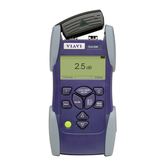
ETTING TARTED Device overview Fig. 1 ORL-55 front and side view JDSU ORL-55... - Page 14 ETTING TARTED Test head cover Test adapter Display Stand (rear side) Power supply socket, USB interface Battery compartment (rear side) key pad Wavelength Select a wavelengthfrom the list Backlight Activate display backlight Previous Step one menu level backwards (without storing settings). MENU/ENTER •...
-
Page 15: Power Supply
Power Supply Different power sources that can be used to operate the ORL-55: • Four 1.5 V dry batteries (Mignon AA size, Alkaline type recommended) • Four 1.2 V NiMH rechargeable batteries (Mignon AA size) • The SNT-121A AC Adapter/Charger Unit •... - Page 16 ETTING TARTED Battery operation Operation with dry batteries 1. Insert batteries (see “Replacing batteries”, page 10) 2. Select Dry battery in the BATTERY CHANGED menu and press Explosion danger Dry batteries can explode if you attempt to recharge them. WARNING Make sure to select Dry battery as battery type when using dry batteries and tzhe SNT-121A AC Adapter/Charger.
- Page 17 ETTING TARTED If the charge cycle does not start although the SNT-121A AC Adapter/Charger Unit is connected, please check the battery setup in the INFO menu. Note: The battery type can not be selected using the instrument keys. To change the battery type, the battery compartment must be opened and at least one battery must be removed for more than five seconds.
- Page 18 ETTING TARTED Operation from AC power The ORL-55 can also be powered from the SNT-121A AC Adapter/Charger only if it is mainly to be used in one place, such as in a laboratory or test workshop. There is a socket on the side of the ORL-55 for plugging in the cable of the AC Adapter/Charger Unit.
-
Page 19: Connecting Optical Cables
ETTING TARTED Operation from USB interface power Although the USB interface is primarily intended for remote control, it can also be used to power the ORL-55. To power the ORL-55 via the USB interface: Just connect a standard USB cable to any USB socket of a PC or USB hub. - Page 20 ETTING TARTED 4. Repeat the procedure if the device is fitted with two ports. 5. Fit the fiber optic cable to the test adapter or close the head cover. Fig. 5 Mounting the JAE test adapter Establishing the VFL connection (optional) The Visual Fault Locator (VFL) is equipped with a universal push pull adapter (UPP) for all standard...
-
Page 21: Basic Operation
ASIC UNCTIONS ASIC UNCTIONS Power ON/OFF To switch the device on: Press [ ] to switch on the device. To switch the device off: Press and hold down [ ] for more than 2 sec. to switch off the device. The ORL-55 has two power modes: •... -
Page 22: Navigating In The Menus
ASIC UNCTIONS Navigating in the menus The measurement display is open. Press [MENU ENTER] to open the MAIN menu. The MAIN menu opens. To select a menu item: 1. Press [] to highlight an item. 2. Press [MENU ENTER] to select the item. To leave a menu without making any changes: ... - Page 23 ASIC UNCTIONS The following table gives a short overview of the menu items. These are explained in the sections below. Edit -Table Edit the wavelengths in the table and the view status (show/hide) of each entry. Select Auto- Activate/deactivate the “Automatic Wavelength Detection”.
- Page 24 ASIC UNCTIONS 2. Highlight the entry to be edited and press [MENU ENTER]. A window opens: 3. Press [MENU ENTER] again to edit the selected wavelength (Edit is already selected). The value to be edited is displayed, the last cipher is highlighted: 4.
- Page 25 Selecting a wavelength from the table Measurement mode is selected. Press to scroll through the table. The wavelength is shown in the left bottom display field and active immediately after selection: Enabling Auto-Lambda mode Auto- is a special feature developed by JDSU that allows you to identify wavelengths automatically.
- Page 26 ASIC UNCTIONS – or – Select DISABLE to switch off Auto- 3. Press [MENU ENTER] to confirm the setting. If Auto mode is activated and a laser source supporting Auto- is connected Auto- will be displayed in the bottom center display pane. Display in Auto-...
-
Page 27: Switching The Backlight On/Off
ASIC UNCTIONS The FACTORY DEFAULT menu opens: 2. Press [MENU ENTER] to set the factory defaults. – or – Press any key to exit from the menu without making any changes. Note: Setting the factory default values does not affect your stored measurement results. - Page 28 ASIC UNCTIONS 7. Press [] to set minutes and press [MENU ENTER]. 8. Press [] to set seconds and press [MENU ENTER]. Note: Date and time must be set again if the device is without any power for more than 1 hour. The device is without any power if •...
- Page 29 ASIC UNCTIONS 3. Press [MENU ENTER] to start the update. 4. Connect the device to the PC via the USB interface. Note: Once the update has been started it cannot be stopped by pressing any of the keys. To stop the update you must disconnect the device from all power sources (adapter/charger, batteries, USB connection).
-
Page 30: Wavelengths
PERATION PERATION The ORL-55 provides three operation modes: 1. Laser Source: The ORL-55 works as a laser source. 2. Power Meter: The ORL-55 works as a power meter. 3. Return Loss Test: The ORL-55 works as a return loss test meter. Both laser source and power meter are activated. - Page 31 PERATION Laser switched off. External power supply The ORL-55 is powered by the external AC adapter when this symbol is shown. Battery status This indicates the battery charge status. If it is not shown, only the AC adapter is active. Power supply via USB The device is powered via the USB interface for remote operation.
- Page 32 PERATION SOURCE MAIN menu Press [MENU ENTER] to open the SOURCE MAIN menu. Select Auto- ON Switch on/off Auto- (see next (OFF) section). Select Modulation Select modulation frequency (see „Signal modulation” on page 29). Level Adjust Set output power level (see „Adjusting the output power level”...
- Page 33 PERATION Signal modulation Modulation frequencies provided by the ORL-55: • CW (Continuous Wave): without modulation • 270 Hz modulation • 1 kHz modulation • 2 kHz modulation To select a modulation frequency Modulation can not be selected, when Auto- is acti- vated.
- Page 34 PERATION To change the output power level: 1. Select Level Adjust. The display changes to EDIT mode, the first wavelength is highlighted: 2. Press [] to increase/decrease value: – press once to change value step wise – hold key to accelerate change speed 3.
-
Page 35: Power Meter Mode
PERATION Power Meter mode Note: The ORL-55 provides measuring optical power levels on singlemode fibres. The test port is – in contrary to “pure” power meters – an Angled Physical Contact (APC) connector. Thus, a test signal can be connected to the ORL-55 via an APC connector only. - Page 36 PERM Power mode • Perm: device remains powered on • ECON: device powers off 20 min. after last operation. Signal modulation • CW (Cont. Wave): without modulation • Auto-: Automatic wavelength detection • 270 Hz, 1 kHz, 2 kHz: modulated signal was detected.
- Page 37 PERATION dB (dBm) Toggle between relative (dB) and absolute (dBm) mode. The displayed mode can be selected - thus it is the mode actually not active. Watt Change display unit to Watt. In the dB/dBm line dBm will be displayed when selecting Watt. Store ABS ->...
- Page 38 PERATION Display absolute level in Watt Highlight Watt and press [MENU ENTER]. Independent from the actually selected display mode (relative or absolute), display will change to absolute mode when selecting Watt. In the dB/dBm menu line dBm will be shown. ...
-
Page 39: Selecting A Wavelength
PERATION 2. Press [] to select wavelength. 3. Press [] to change value 4. Press [MENU ENTER] to accept setting. Selecting a wavelength The sensitivity of the photo diode depends on the wavelength. To ensure a correct reading the wavelength setting of the device must match the wavelength of the incoming signal. -
Page 40: Return Loss Test Mode
PERATION Return loss measurement In the Return Loss mode a signal is send to the DUT from the internal laser source. The power level reflected from the DUT is measured and compared to the transmitted signal. The result of the return loss is displayed at the ORL-55. - Page 41 PERATION ORL MAIN menu Press [MENU ENTER] to open the ORL MAIN menu. Normalize Stores the internal noise in ORL Open Port mode as reference value. Manage Display and delete stored data (see Memory „Memory Management” on page 39). Configuration Change basic settings (see „Device...
-
Page 42: Vfl Mode (Optional)
PERATION 5. Select Normalize Open Port. The normalization will be performed and the display will switch to measurement mode. The display shows “High”. Note: The normalization will be automatically performed for all wavelengths. VFL mode (optional) If the Visual Fault Locator (VFL) option is available, the MAIN menu additionally shows the item Switch To VFL Mode. -
Page 43: Memory Management
EMORY ANAGEMENT EMORY ANAGEMENT General information The ORL-55 allows you to save the measured power level values in a structured data memory and recall them as required. Up to 350 results can be stored. All data is saved to a non-volatile memory (E PROM). -
Page 44: Saving Results Successively
EMORY ANAGEMENT Saving results successively Results are stored simply by pressing the STORE key. Each time the key is pressed, the next memory location will be used to store the current result. If the memory is initially empty, the memory starts with Group 001 and Meas 001. -
Page 45: Displaying Stored Results
EMORY ANAGEMENT Fig. 12 Display if selected memory location is already occupied. Press [MENU ENTER] to overwrite data with new data. Press [PREV] if you do not want to overwrite existing data. Displaying stored results Displaying the last measurement results stored is probably the function you will use the most often. - Page 46 EMORY ANAGEMENT To select another Measurement in the current Group: Press [] to increase/decrease the Meas #. To select another Group and Measurement: 1. Press [MENU ENTER]. The MANAGE MEMORY menu opens: 2. Press [MENU ENTER] to select Select Group. The current Group and Meas 001 will be displayed: 3.
-
Page 47: Selecting The Store Location
EMORY ANAGEMENT Selecting the store location When you press the [Store] key in measurement mode, the results are stored at the active memory location. Each time you press the key, the Meas # is incremented but the Group # remains the same. You cannot select the memory location, Meas # or Group # in measurement mode. -
Page 48: Clearing The Memory
EMORY ANAGEMENT Clearing the memory You can store up to 350 data sets in the ORL-55. Each data set can contain up to 3 measurements in Auto mode (in conjunction with a JDSU OLS-55 light source). Each data set contains the wavelength, the relative power level and reference value or the absolute power level, and the date / time when it was stored. -
Page 49: Reading Out The Result Memory
4. Press [PREV] to exit from the menu. Note: If you now store results, they will be stored at the memory location for the cleared Meas # of the last Group displayed. To clear all the data of a Group 1. - Page 50 EMORY ANAGEMENT Copying the result memory to a memory stick The result memory can be copied to a memory stick plugged into the USB port on the connector panel. This allows you to store a large amount of data in ASCII format.
- Page 51 EMORY ANAGEMENT To start a new data transfer: 1. Open the main menu and select the displayed item (menu items may vary depending on the model and operating mode). The window opens to start the transfer. 2. Press [MENU ENTER] to transfer the contents of the measurement memory to the memory stick.
-
Page 52: Maintenance
AINTENANCE AINTENANCE Dangerous voltage and invisible laser radiation Maintenance or cleaning of the device when it is connected up or operating may damage the device or injure you. Make sure that the device is switched WARNING off and disconnected from all power sources and optical radiation sources before maintenance or cleaning. -
Page 53: Cleaning The Instrument
AINTENANCE Cleaning the instrument If the instrument gets dirty through use, you can clean it using a soft cloth moistened with a mild solution of detergent. Water and cleaning fluids The device may be damaged or destroyed if water or cleaning fluids CAUTION get inside it. -
Page 54: Remote Control
EMOTE ONTROL EMOTE ONTROL Communication interface The ORL-55 is equipped with a USB interface for remote control via a PC. The driver files needed on the PC for this can be download from www.jdsu.com. The OFS-355 Download Manager is quickly and easily installed (see next chapter). -
Page 55: Parameters
EMOTE ONTROL Parameters Overview Utility commands *IDN? *OPC? :SYST:PERM:POW :DISP:CONT :DISP:CONT? :SYST:ERR? :SYST:DEV:DEF :SYST:LANG :SYST:LANG? :SYST:DATE :SYST:DATE? :SYST:TIME :SYST:TIME? :DEV:MODE :DEV:MODE? Laser Source commands :SYST:SOUR:NUMB? :SYST:SOUR:WAV:VAL? :SYST:SOUR:POW:MAX? :SYST:SOUR:POW:MIN? :SYST:SOUR:MODE :SYST:SOUR:MODE? :SOUR:ID :SOUR:ID? :SOUR:WAV:AUTO :SOUR:WAV:AUTO? :SOUR:MOD :SOUR:MOD? :SOUR:POW JDSU ORL-55... - Page 56 EMOTE ONTROL :SOUR:POW? :SOUR:STAT :SOUR:STAT? Power Meter commands :POW:CAL:WAV:MAX? :POW:CAL:WAV:MIN? :POW:CAL:WAV:TAB :POW:CAL:WAV:TAB? :POW:CAL:WAV :POW:CAL:WAV? :POW:DISP:UNIT :POW:DISP:UNIT? :POW:REF:STAT :POW:REF:STAT? :POW:REF:VAL :POW:REF:VAL? :POW:WAV:AUTO :POW:WAV:AUTO? :POW:FETC:AM:AUTO:FREQ? :POW:FETC:AM:INT:FREQ? :FETC:MEAS:VAL? Return Loss commands :SOUR:ID :SOUR:ID? :SOUR:STAT :SOUR:STAT? :RET:LOSS:NORM :FETC:MEAS:VAL? Memory Management commands :MEM:FREE? :MEM:USED? :MEM:GROU :MEM:GROU? :MEM:GROU:MEAS ORL-55...
- Page 57 EMOTE ONTROL :MEM:GROU:MEAS? :MEM:ID:MEAS? :MEM:STOR:MEAS :MEM:REC:MEAS? :MEM:REC:ALL? :MEM:DEL:MEAS :MEM:DEL:GROU :MEM:DEL:ALL Utility commands Command Parameter type / Response type / string Unit / Info *IDN? Returns the unique identification of the device. Response type: <STRING_RESPONSE_DATA> e.g. JDSU Germany GmbH, ORL-55/01,A-0106,V03.30 *OPC? Returns “1”...
- Page 58 Command Parameter type / Response type / string Unit / Info :SYST Returns the oldest error in the error :ERR? queue. Response type: <NR1>, <STRING_RESPONSE_DATA> e.g. -100,“Command error” :SYST Sets the device parameters to their :DEV default values. :DEF :SYST Sets the language.
- Page 59 EMOTE ONTROL Command Parameter type / Response type / string Unit / Info :SYST Returns the time (hh,mm,ss). :TIME? e.g. 23,59,59 :DEV:MODE Sets the device operating mode. Parameter type: <MNEMONIC> Modes: • SOUR: Laser Source mode • POW: Power Meter mode •...
- Page 60 Command Parameter type / Response type / string Unit / Info :SYST Returns the minimum power level :SOUR [dBm x 100] of the specified LASER :POW source. :MIN? Parameter type: <NR1> e.g. :SYST:SOUR:POW:MIN? 2 :SYST Emulates the LASER source :SOUR modulation of the former ACTERNA :MODE device OLS-15.
- Page 61 EMOTE ONTROL Command Parameter type / Response type / string Unit / Info :SOUR Sets Auto- modulation ON/OFF. :WAV Parameter type: <BOOLEAN> :AUTO • 0: Auto- OFF • 1: Auto- ON Default setting: OFF (0) :SOUR Returns Auto- modulation status. :WAV •...
- Page 62 EMOTE ONTROL Command Parameter type / Response type / string Unit / Info :SOUR Returns the power level [dBm x 100] :POW? for the specified LASER source. Parameter type: <NR1> e.g. :SOUR:POW? 1 :SOUR Sets state of the LASER ON/OFF. :STAT Parameter type: <BOOLEAN>...
- Page 63 EMOTE ONTROL Command Parameter type / Response type / string Unit / Info Returns the contents of the -Table. :POW :CAL Response type: <NR1,NR1,...> :WAV :TAB? :POW Selects the calibration wavelength from the -Table. :CAL :WAV See :SYST:CAL:WAV:TAB? for more details.
- Page 64 EMOTE ONTROL Command Parameter type / Response type / string Unit / Info :POW Returns the type of power level :REF display. :STAT? Response type: <BOOLEAN> • 0: absolute value • 1: relative value :POW Sets the value for the specified :REF wavelength (to which the power level :VAL...
- Page 65 EMOTE ONTROL Command Parameter type / Response type / string Unit / Info :POW Returns :FETC • “1”, if an Auto- modulation frequency was detected on the :AUTO incoming signal. :FREQ? • “0” otherwise :POW Returns :FETC • “0”, if the incoming signal is not modulated or Auto-...
- Page 66 EMOTE ONTROL Return Loss commands Command Parameter type / Response type / string Unit / Info :SOUR:ID „:SOUR:ID” on page :SOUR:ID? „:SOUR:ID?” on page :SOUR „:SOUR:STAT” on page :STAT :SOUR „:SOUR:STAT?” on page :STAT? :RET Triggers the “Normalizing Open Port” :LOSS function in Return Loss mode.
- Page 67 EMOTE ONTROL Remote command description This command is only allowed in the RETURN LOSS MODE with LASER ON. If the unit is in a different mode, the unit will display an error message. This command will switch the unit to user-specific reference values.
- Page 68 EMOTE ONTROL Memory Management commands Command Parameter type / Response type / string Unit / Info :MEM Returns number of how many :FREE? measurements can still be stored until memory is full. :MEM Returns number of measurements :USED? stored. :MEM Selects the group (1...350) where the :GROU measurement is stored, deleted or...
- Page 69 EMOTE ONTROL Command Parameter type / Response type / string Unit / Info :MEM Stores the current measurement :STOR under the current measurement :MEAS group and number. Note: If this command is repeated immediately (i.e. with no other commands, such as :MEM:REC:MEAS? in between), the identifier increments by 1 for the next store operation.
- Page 70 EMOTE ONTROL OFS-355 Download Manager The OFS-355 Download Manager is a free download offered by JDSU which allows you to easily transfer stored measurement data to a PC, to enhance the performance of your SMART optical handheld devices, and to speed up production of your test reports. To download the OFS-355 Download Manager: 1.
- Page 71 EMOTE ONTROL Fig. 14 Acceptance report • The OFS-355 Download Manager allows remote control of a device connected to the PC. You can use this to measure the signal power level at intervals (and at several wavelengths) and transfer the data to the PC immediately.
-
Page 72: Specifications
PECIFICATIONS PECIFICATIONS Laser Source Laser safety IEC 60825-1:2007 Laser classification CLASS 1 LASER PRODUCT Selectable wavelengths BN 2287/21 1310/1550 nm BN 2287/22 1310/1490/1550 nm BN 2287/23 1310/1550/1625 nm Spectral width (RMS) < 5 nm Outputs single Output power 1310, 1550, 1625 nm -3.00 to -10 dBm 1490 nm -6 to -13 dBm... -
Page 73: Power Meter
PECIFICATIONS Power Meter Adjustable 1260 nm to 1650 nm, wavelength range in 1 nm steps Calibrated 1310 nm, wavelengths 1550 nm, 1625 nm Photo diode InGaAs Display range -70 dBm to +6 dBm Resolution 0.01 dB, 0.001 µW Max. permitted level +6 dBm ... -
Page 74: General Specifications
PECIFICATIONS General specifications Wavelength Automatic switching and displaying up detection to three wavelengths simultaneously Reference Transfer of measured value or entry of level any reference level in the range -80 to +30 dBm, one Reference Level for each wavelength Modulation 270 Hz, 1 kHz, 2 kHz detection Warm up time... - Page 75 PECIFICATIONS Power supply Dry batteries 4 x AA, 1.5 V Rechargeable NiMH, batteries 4 x AA, 1.2 V, internal recharge Operating time with dry/rechargeable typ. 65 h batteries (without backlight) AC line operation with separate SNT-121A AC Adapter/ Charger Unit Power saving mode auto power-off after appr.
-
Page 76: Snt-121A Adapter/Charger
PECIFICATIONS Dimensions and weight Dimensions (w x h x d) 95 x 60 x 195 mm Weight approx. 500 g (including batteries) SNT-121A AC Adapter/Charger Unit Nominal line voltage range 100 to 240 VAC Nominal line frequency range 47 to 63 Hz Power consumption max. -
Page 77: Ordering Information
RDERING NFORMATION 1310/1550 nm BN 2287/21 1310/1490/1550 nm BN 2287/22 1310/1550/1625 nm BN 2287/23 Calibration report BN 2286/90.01 Accessories Optical adapters BN 2150/00.xx OCK-10 Optical cleaning kit BN 2229/90.21 Cleaning tape for optical connectors BN 2229/90.07 Spare tape for optical cleaning tape BN 2229/90.08 NiMH cells (AA size, 1.2 V) BN 2237/90.02... -
Page 78: Index
NDEX Absolute mode 39 Information about device 28 AC line plug adapter 17 Accessories 79 Lambda-Table, edit 25 Auto-Lambda Laser safety 6 enabling mode 26 Laser Source mode 32 on/off 34 Memory position 50 Backlight 22 Memory structure 45 Batteries Menu Danger 15 Meter Main 38... - Page 79 NDEX Power meter 59, 65 Utility 60 Results 46 Return Loss Test mode 41 Saving results 46 Shipping damage 11 Signal modulation 34 Source Main menu 33 Technical Highlights 1 Test adapter, mounting 19 Time 29 Updating the firmware 30 VFL mode 44 JDSU ORL-55...
- Page 80 JDSU Environmental Management Program Superb performance and high quality have always characterized JDSU datacom and telecom measurement technology products. In this same world-class tradition, JDSU has an established, proactive program of environmental management. Environmental management is an integral part of JDSU’s business philosophy and strategy requiring the development of long-term, productive solutions to problems in the key areas of economics, technology, and ecology.
- Page 81 Environmental management partnerships JDSU encourages our customers and suppliers who take this responsibility seriously to join JDSU in establishing their own environmental management programs. Recycling used products This product complies with the European Union Waste Electrical and Electronic Equipment directive (WEEE), 2002/96/EC. This product should not be disposed of as unsorted municipal waste and should be collected separately and disposed according to your national regulations.
Need help?
Do you have a question about the ORL-55 Series and is the answer not in the manual?
Questions and answers