Advertisement
Quick Links
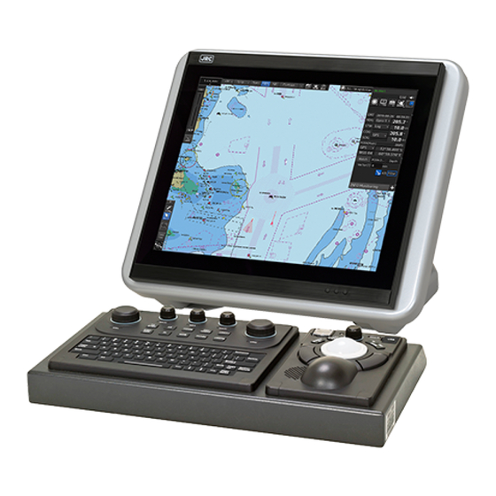
JAN-7201S/9201S
Simple
ECDIS
Instruction Manual
<Reference>
Overview
Name and Function of Each Unit
Common Basic Operations
Range and Bearing Measurement Methods
Target Tracking and AIS
Functions of the ECDIS
Route Planning
Route Monitoring
Monitoring a Dragging Anchor
Automatic Sailing (Unsupported)
Operating a Chart
Creating a User Map/ Updating a Chart
Manually
Logbook
Setting Up Screen View
Setting Up Alerts
Setting Up the Operation Mode
Adjusting and Setting Up Equipment (for
Services)
Playing Back Data Recorded During
Navigation [Playback]
Maintenance & Inspection
Failures and After-Sale Services
About Disposal
Specifications
Alert List
Menu List and Materials
1
2
3
4
5
6
7
8
9
10
11
12
13
14
15
16
17
18
19
20
21
22
APP A
APP B
Advertisement

Related Manuals for JRC JAN-7201S


Summary of Contents for JRC JAN-7201S
- Page 1 Overview Name and Function of Each Unit Common Basic Operations Range and Bearing Measurement Methods Target Tracking and AIS Functions of the ECDIS JAN-7201S/9201S Route Planning Route Monitoring Monitoring a Dragging Anchor Automatic Sailing (Unsupported) Operating a Chart Simple Creating a User Map/ Updating a Chart...
- Page 3 Contents Reference Section 17 Adjusting and Setting up Equipment (for Services) ....17-1 17.1 Service Menu ........................17-1 17.1.1 To display the Service menu: ..................17-1 17.2 Radar Adjustment ........................ 17-3 17.2.1 Displaying the [Adjustment] dialog box ............... 17-3 17.2.2 Performing basic adjustments on the radar ..............17-4 17.2.2.1 Displaying the [Basic Adjustment] dialog ..............
- Page 4 17.3.8 Setting Sensor ......................17-29 17.3.8.1 Displaying the [Sensor] dialog ................17-29 17.3.8.2 Displaying an alert set point ................17-29 17.3.8.3 Setting the GPS switching linkage function ............17-30 17.3.9 Setting Route Sharing ....................17-31 17.3.9.1 Displaying the [Route Sharing] dialog ..............17-31 17.3.9.2 Selecting a route sharing method ...............
- Page 5 19.3.1.2 The Trackball ...................... 19-16 19.4 Performance Check ......................19-17 19.4.1 Starting Selftest functions ..................19-17 19.4.2 Confirming the screen status [Monitor Test] ............. 19-18 19.4.3 Confirming the operation of the operation unit [Key Test] ......... 19-22 19.4.4 Confirming the alert sound [Sound Test] ..............19-23 19.4.5 Testing the brightness of LED [Light Test] ..............
- Page 6 About Disposal of This Equipment ..................21-1 21.2 Chinese Version RoHS ....................... 21-2 Section 22 Specifications ................22-1 22.1 JAN-9201S .......................... 22-1 22.2 JAN-7201S .......................... 22-2 22.3 Display Unit ......................... 22-3 22.4 Central Control Unit ......................22-6 22.5 Power Supply Unit ....................... 22-7 22.6 Trackball Operation Unit .....................
- Page 7 B.1.8 TT/AIS ................B-10 B.1.9 Tools .................. B-13 B.1.10 View ..........................B-16 B.1.11 Alert ............B-21 B.1.12 Settings ........... B-22 B.1.13 Chart Maintenance ............B-27 B.1.14 Maintenance ..........B-29 B.1.15 Help ............B-31 B.1.16 Code Input ..........B-32 B.1.17 Service ............
- Page 8 B.2.7 Manual Update (S-57) ....................B-52 B.2.7.1 Symbol ........................B-52 B.2.7.2 Simple line ......................B-52 B.2.7.3 Line - Circle ......................B-52 B.2.7.4 Line - Ellipse ......................B-52 B.2.7.5 Arc ........................B-53 B.2.7.6 Polygon ......................... B-53 B.2.7.7 Area - Circle ......................B-53 B.2.7.8 Area - Ellipse ......................
- Page 9 B.10 Data Format of the File that can be Imported/Exported in the ECDIS ......B-152 B.10.1 File Types ........................B-152 B.10.2 File Name ........................B-152 B.10.3 CSV File Data Structure ................... B-152 B.10.4 Route File ........................B-153 B.10.5 User Map File ......................B-155 B.10.6 Log Book File ......................
- Page 10 Contents...
- Page 11 1 Section 17 Adjusting and Setting up Equipment (for Services) This section describes the methods for radar adjustment, installation verification, and maintenance that are conducted by the service staff by using the Service menu at installation construction of this equipment. Any adjustments must be made by specialized service personnel.
- Page 12 Change over to the second page using the page switching button, and click the [Code Input] button. The password input dialog is displayed. Enter 0 in Password. Click on the [MENU] button on the left toolbar. The menu is displayed. Change to the 2nd page by using the page change button.
- Page 13 1 17.2 Radar Adjustment Note In case of JAN-7201S/9201S, overlay function is not available by function restriction. Therefore the setup is not available. Use the [Adjustment] dialog box to adjust the radar of this equipment. 17.2.1 Displaying the [Adjustment] dialog box Clicking the [Adjustment] button in the submenu displays the [Adjustment] dialog box.
- Page 14 17.2.2 Performing basic adjustments on the radar Perform basic adjustments on the radar by using the [Basic Adjustment] dialog. 17.2.2.1 Displaying the [Basic Adjustment] dialog When you select [Basic Adjustment] in the classification pane, the [Basic Adjustment] dialog is displayed in the edit pane. 17.2.2.2 Adjusting the bearing Adjust the bearing so that the bearing of the target measured by the compass on the ship and the...
- Page 15 1 Input an adjustment value in the input box so that the bearing of the target that was measured in Step 2 indicates a correct bearing. (0 to 359.9) For the method of using the numeric input keyboard, refer to "3.16.2 Name and function of each section of the keyboard".
- Page 16 Measure the height from the sea surface to the radar antenna. In the [Antenna height] combo box, select the setting value corresponding to the height of the antenna that was measured in step 1. • Under 5 m • 5-10 m •...
- Page 17 1 17.2.4.2 Performing MBS adjustment Click on the [Initial Level] (MBS initial level) input box. A numeric value input keyboard is displayed. Enter an initial level of MBS so that the image of main bang becomes optimum (faint image remains on the screen. (0 to 1023) For the method of using the numeric input keyboard, refer to "3.16.2 Names and functions of the sections of the keyboard".
- Page 18 17.3 Verifying Installation and Initial Setting Use the [Installation] dialog box to verify the installation of this equipment and perform initial setting. 17.3.1 Displaying the [Installation] dialog box Clicking on the [Installation] in the submenu, the [Installation] dialog box appears. The [Installation] dialog box consists of the classification pane and the edit/result pane.
- Page 19 1 17.3.2 Verifying/Setting CCRP (Consistent Common Reference Point) Set a measurement reference position (CCRP) on own ship by using the [CCRP] dialog. 17.3.2.1 Displaying the [CCRP] dialog When you select [System Configuration] in the first classification pane and [CCRP] in the second classification pane, the [CCRP] dialog is displayed in the edit/result pane.
- Page 20 17.3.2.2 Setting CCRP Set the following items in the [CCRP] dialog. Setting Item Description of Setting Setting Value Length (of ship) Enter the ship's length in the box. 1.0 to 1022.0m Beam (ship's width) Enter the ship's width in the box. 1.0 to 126.0m GPSx Enter the equipment positions of GPSx in the...
- Page 21 1 Setting Item Description of Setting Setting Value Radio button on the left Select the position to be used as the ship's CCRP CCRP1 side of each CCRP by clicking the applicable button. CCRP2 CCRP3 CCRP4 Anchor1 An anchor position can be set as an offset from the If Length=a and Beam=b: stern center.
- Page 22 17.3.3.1 Displaying the [Serial Port] dialog When you select [System Configuration] in the first classification pane and [Serial Port] in the second classification pane, the [Serial Port] dialog is displayed in the edit/result pane. Tab name display 17.3.3.2 [Selftest] lamp light colors The [Selftest] lamp indicates the Selftest result on whether or not the sentence of the sensor specified for each serial port has been received successfully and the status of ISW/MTR/Serial OPU.
- Page 23 1 Setting a serial port on the CCU Set each item as follows. "Table A: Sensors that can be selected by serial ports on CCU" shows selectable sensors. However, the sensors that actually can be selected vary depending on the equipment setting. For the sensor communication speed, refer to "Selectable baud rates".
- Page 24 Setting serial ports on SLC/ALC Set the serial ports on SLC/ALC that is installed as follows. Setting item Setting contents Setting value CH1 to CH8 1. Click on any of the tabs, SLC1(M) to Enable: Selected (RS-422) SLC4(M)/SLC1(S) to SLC4(S)/ALC1 to ALC4. Disable: Clear 2.
- Page 25 1 17.3.3.4 To change the communication settings of the Serial Port Click the [Detail] button of the enabled serial port and display the [Detail] dialog. When selecting CH1 to CH7 When selecting CH8 to CH10 APP A APP B Section 17 Adjusting and Setting up Equipment (for Services) 17-15...
- Page 26 The setting target can be checked with [Source Device] display, [Terminal] display and [Sensor] display. Perform the settings shown in the following table and then click on the [Set] button. Setting Item Description of Setting Setting Value Baud Rate Select the baud rate of the serial port on the Selectable baud rates vary combo box.
- Page 27 1 Selectable baud rates Serial port Baud rate Serial point on CCU Gyro (at selection of Heading Sensor(NMEA)) 4800/38400 Gyro (at selection of Heading Sensor(Gyro I/F)) Fixed to 38400 Log (at selection of Log(NMEA)) Fixed to 4800 Log (at selection of Log(Gyro I/F)) Fixed to 38400 Fixed to 4800 Fixed to 38400...
- Page 28 17.3.4 Setting a System Function Verify the setting of the system function of this equipment and perform initial setting by using the [System Function] dialog. 17.3.4.1 Displaying a [System Function] dialog When you select [System Configuration] in the first classification pane and [System Function] in the second classification pane, the [System Function] dialog is displayed in the edit/result pane.
- Page 29 1 17.3.4.3 Setting a system function In the [System Function] dialog, allocate the system functions to be connected for LAN. Add a system function (New equipment) Click the [Add] button and display the [System Function (Add)] dialog. Perform the settings shown in the following table and then click on the [Set] button. Setting Item Description of Setting Setting Value...
- Page 30 Note: IAS and NAVTEX: Only NMEA is supported. CAM is settings for connecting to an external CAM by LAN. *2: The Mnemonic of Talker ID that can be selected are indicated below. AG, AI, BN, CA, CR, EI, ER, GP, HC, HE, II, JA, JB, JC, JD, JE, JF, JG, JH, RA, SD, SG, SI, SS, TC, TI, U0, U1, U2, U3, U4, U5, U6, U7, U8, U9, VD, VR, WI, ZA *3: Clusters are groups of functionalities aimed at a responsible operator, which can be distributed over systems.
- Page 31 1 *6: Talker ID Mnemonic, Talker ID Instance No, Transmission Group (Control/Data), Transmission Group (Alert) Transmit and Transmission Group (Alert) Receive can also be set by selecting Equipment on the preset combo box. The following default values will be set. Equipment System TalkerID...
- Page 32 Equipment System TalkerID TalkerID Transmission Transmission Transmission Function Mnemonic Instance Group Group (Alert) Group (Alert) (Control/Data) Transmit Receive Equipment(Alert) 3 General General 0004 MISC CAM1 Equipment(Alert) 4 General General 0005 MISC CAM1 Equipment(Alert) 5 General General 0006 MISC CAM1 Equipment(Alert) 6 General General 0007...
- Page 33 1 Add a system function (Existing equipment) Select the check box and Click the [Add] button and display the [System Function (Add)] dialog. Perform the settings referring to Add a system function (New equipment). Equipment can not be changed on the [Detail] dialog. Edit a system function Select the check box and click the [Edit] button and display the [System Function (Edit)] dialog.
- Page 34 Select the check box and click the [Delete] button. Selected a system function is deleted. Note: - Set the each setting according to the transmission specifications of the equipment connected to the LAN. - Equipment connected to the SLC / ALC serial port or CCU cannot add or edit or delete system functions. System function of Equipment connected to the SLC / ALC serial port or CCU are registered automatically by serial port setting on [Serial Port] dialog.
- Page 35 1 17.3.5 Setting Ship's Parameters Set parameter values of own ship by using the [Ship’s Parameters] dialog. 17.3.5.1 Displaying the [Ship’s Parameters] dialog When you select [Ship's Parameters] in the classification pane, the [Ship’s Parameters] dialog is displayed in the edit/result pane. APP A APP B Section 17 Adjusting and Setting up Equipment (for Services)
- Page 36 17.3.5.2 Setting own ship's parameters Set the following items in the [Ship’s Parameters] dialog. Setting Item Description of Setting Setting Value Ship's Name Enter own ship's name in the box. Max. 20 characters Length (of ship) Enter own ship's length in the box. 1.0 to 1022.0 m Beam (ship's width) Enter own ship's beam in the box.
- Page 37 17.3.6 Setting the automatic sailing system Note In case of JAN-7201S/9201S, automatic sailing function is not available by function restriction. Therefore the setup is not available. By using the [Autosail] dialog, verify and initialize the automatic sailing system that is installed in this equipment.
- Page 38 17.3.7 Setting the AIS password Set the AIS password by using the [AIS] dialog. 17.3.7.1 Displaying the [AIS] dialog When [Settings] is selected in the 1st classification pane and [AIS] is selected in the 2nd classification pane, the [AIS] dialog is displayed in the edit/result pane. 17.3.7.2 Setting the AIS password Set the following item on the [AIS] dialog.
- Page 39 1 17.3.8 Setting Sensor The alert set point (Alarm Limit) display and GPS switching interlocking function can be set for depth display on the “Sensor” dialog. 17.3.8.1 Displaying the [Sensor] dialog When [Settings] is selected in the 1st classification pane and [Sensor] is selected in the 2nd classification pane, the [Sensor] dialog is displayed in the edit/result pane.
- Page 40 17.3.8.3 Setting the GPS switching linkage function Check the [Synchronise position sensor selected Master] check box. A badge is displayed on the Top screen (own ship's position) of the equipment with the GPS Selector control authorization. When the GPS switching linkage function is enabled, the GPS sensor source with other equipment is linked.
- Page 41 1 17.3.9 Setting Route Sharing In the "Route Sharing" dialog, change the route sharing method used for route sharing. 17.3.9.1 Displaying the [Route Sharing] dialog When [Settings] is selected in the 1st classification pane and [Route Sharing] is selected in the 2nd classification pane, the [Route Sharing] dialog is displayed in the edit/result pane.
- Page 42 17.3.10 Setting the GPS Shared Route This function enables the switching between new route sharing and old route sharing and the setting of data route transmission/reception to ON/OFF. 17.3.10.1 Displaying the [GPS Shared Route] dialog When [Settings] is selected in the 1st classification pane and [GPS Shared Route] is selected in the 2nd classification pane, the [GPS Shared Route] dialog is displayed in the edit/result pane.
- Page 43 1 Setting item Setting contents Setting value Sharing of a new route can be set to On/Off. On: Default Sharing of an old route can be set to On/Off. Off: Default Data Route Send Data route transmission can be set to On/Off. On: Default [Send to GPS] of [Route Planning]-[▼] is enabled.
- Page 44 17.3.11 Setting the Route Plan Exchange You can switch the enable / disable of route plan exchange and make various settings. 17.3.11.1 Displaying the [Route Plan Exchange] dialog When [Settings] is selected in the 1st classification pane and [Route Plan Exchange] is selected in the 2nd classification pane, the [Route Plan Exchange] dialog is displayed in the edit/result pane.
- Page 45 1 17.4 Maintenance Use the [Maintenance] dialog box for maintenance operation of this equipment. 17.4.1 Displaying the [Maintenance] dialog box Clicking the [Maintenance] button in the submenu displays the [Maintenance] dialog box. The [Maintenance] dialog box in the submenu consists of the classification pane and the edit/result pane.
- Page 46 17.4.2 Managing storage When you select [Storage] in the first classification pane and [Management] in the second classification pane, the [Management] dialog is displayed in the edit/result pane. The total storage capacity and free space on each of the drives (C and D) are displayed in the [Drive Information] list.
- Page 47 1 Section 18 Playing Back Data Recorded During Navigation The following information recorded during navigation can be played back on the screen. • Own ship's information • Other ship's information • Route information • Alarm information Click on the [Playback] button on the Task Menu. APP A APP B Playing Back Data Recorded During Navigation...
- Page 48 The following screen appears and the playback controller is displayed. (Playback mode) Playback controller The playback controller can move to any position on the screen; however, it cannot be minimized. Playing Back Data Recorded During Navigation 18-2 Section 18...
- Page 49 1 18.1 Playback Controller The view of the playback controller can be switched between simplified display and full display by clicking the View Change button ( Simplified Display Full Display [Control] section [12] [13] [11] [14] [10] APP A APP B [Playback Information] Section Playing Back Data Recorded During Navigation...
- Page 50 Upper Part of the Playback Controller Number Name Function Playback time The playback time is displayed. [X] (Close) button Exits playback. Playback slider The progress of playback is displayed. The playback position can be changed by moving the slider control. •...
- Page 51 1 [Playback Information] Section Information of each record data is displayed. Name Function Chart The cell having the cell name of the chart being displayed when recorded is shown. Scale The scale of the chart being displayed when recorded is shown. Edition The version of the cell having the cell name of the chart being displayed when recorded is shown.
- Page 52 18.2 Selecting Playback Data Select the navigation record data you want to play back. Click on the Drive Selection box to open the list, and then select a data drive storing navigation record data. Folders saved on the selected data drive are displayed in tree view. Select a folder storing the navigation record data you want to play back (ex.
- Page 53 1 18.3 Playing Back Logbook Data Play back the selected logbook data. To Start Playback Click on the Playback button. Playback of navigation record data starts. The Playback button is highlighted during playback, and the playback time indicator and the playback slider control are also linked with the playback.
- Page 54 18.3.1 Changing the playback speed Change the playback speed of logbook data. Select a playback speed from the list in the playback speed selection box. Navigation record data is played back at the selected playback speed. The time shown on the playback time indicator and the progress shown on the playback slider control change according to the playback speed.
- Page 55 1 18.4 Exiting the Playback Mode Other tasks cannot be executed while the Playback dialog box is being displayed (during the Playback mode). To execute other tasks, exit the Playback mode. Click on the [X] (Close) button on the playback controller. The Exit Confirmation dialog box appears.
- Page 56 18.5 Outputting Navigation Record Data Select navigation record data from the File Manager submenu of the Tools menu, and then copy it to the output destination you specify. Open the File Manager submenu of the Tools menu. Drive selection box File type [Copy>>] (output destination)
- Page 57 1 By clicking on the Calendar icon, specify the duration of the logbook data to be output. The selected dates appear in the output data interval selection boxes. Specify the drive of the output destination from the output destination drive selection box and the output destination folder from the folder tree.
- Page 58 18.6 Functional Restrictions When in the Playback Mode Some functions are restricted in playback mode. The restricted functions are disabled. Playing Back Data Recorded During Navigation 18-12 Section 18...
- Page 59 Section 19 Maintenance & Inspection 19.1 Maintenance Functions Executed from Menu This section explains maintenance functions that are executed from the menu. 19.1.1 Starting maintenance functions Click on the [Menu] button on the left Tool Bar. The menu is displayed. Click on the [Maintenance] button on the menu.
- Page 60 [1] [X] button Click on this button to close the [Date/Time/Time Zone] dialog box. [2] [Date] Set the year, month and day on the calendar. For the details of how to use the calendar, refer to "3.17 Setting a Date and a Time [Calendar Operation)".
- Page 61 19.1.3 Confirming System Information System information can be confirmed. Click on the [Menu] button on the left Tool Bar. The menu is displayed. Click on the [Maintenance] - [System Information] button on the menu. The [System Information] dialog box appears. The contents of the dialog will be switched by clicking on the selection tabs provided in the dialog box.
- Page 62 19.1.3.1 Confirming Software Information When you want to use a USB flash memory to read or write a file, make sure in advance that the USB flash memory is not affected by a computer virus. If the indicator is infected with a virus, other equipment will also be infected, with the result that a trouble will occur.
- Page 63 [2] Software information Item Displayed information Jxx-xxxx Type and model name of the system Application Version of the application software Maintenance No. 7-digit maintenance number TXRX Version of the software used for the radar transmitter-receiver unit * This information is displayed when the system is equipped with the RADAR function.
- Page 64 [1] [X] Click on this button to close the [System Information] dialog box. [2] [ARCS Information] The ARCS PIN number and User Permit are displayed. [3] [S-63 Information] The S-63 User Permit is displayed. [4] [Save to USB Device] (Saving to USB flash memory) button Click on this button to save the displayed information in a USB flash memory in the text format.
- Page 65 19.1.3.3 Confirming the compliant standards for the equipment When you want to use a USB flash memory to read or write a file, make sure in advance that the USB flash memory is not affected by a computer virus. If the indicator is infected with a virus, other equipment will also be infected, with the result that a trouble will occur.
- Page 66 [3] [Save to USB Device] (Saving to USB flash memory) button Click on this button to save the displayed information in a USB flash memory in the text format. 19.1.4 Confirming Operating Time Confirm the operating time of this system. Click on the [Menu] button on the left Tool Bar.
- Page 67 19.1.5 Displaying and Resetting the Current Voyage Distance This equipment displays the current voyage distance (estimated voyage distance) that is calculated from the speed over the ground and the speed through the water. The voyage distance can also be reset. Note While the ship is anchored or sailing at low speed, it takes up to around 2 minutes to reset the current voyage distance.
- Page 68 [3] [Clear] button The voyage distance is reset. When this button is clicked on, a confirmation dialog is displayed. To reset the voyage distance, click on the [Yes] button. When not resetting the voyage distance, click on the [No] button. Memo When the voyage distance is reset in the [Voyage Distance] dialog, the voyage distance in the event detailed information in the logbook is also reset.
- Page 69 19.1.6 Setting and confirming the Sensor Source Set and confirm the sensor source. Click on the [Menu] button on the left Tool Bar. The menu is displayed. Click on the [Maintenance] - [Sensor Selection/Status] button on the menu. The [Sensor Selection/Status] dialog box appears. [1] [X] button Closes [Sensor Selection/Status] dialog box.
- Page 70 Setting item Setting contents Setting value Select a heading sensor source from the combo box. Heading MAN, Gyro x, MAG, * The sources that can be selected vary according to the installation. ("x" indicates the unit * When GyroSW is enabled, only Gryo and MAN can number) be selected.
- Page 71 19.1.7 Checking the Route Plan Exchange Log Checking the Route Plan Exchange Log. Click on the [Menu] button on the left Tool Bar. The menu is displayed. Click on the [Maintenance] - [Route Plan Exchange Log] button on the menu. [Route Plan Exchange Log] dialog box appears.
- Page 72 19.2 General Maintenance DANGER Never attempt to check or repair the inside of the equipment. Checking or repair by an unqualified person may cause a fire or an electric shock. Contact our head office, or a nearby branch or local office to request servicing.
- Page 73 19.3 Maintenance on Unit 19.3.1 Display unit When cleaning the screen and Trackball of Operation Unit, do not wipe hard with a dry cloth. Also, do not use glass cleaner, alcohol, gasoline, or thinner to clean the screen. Also avoid wiping with water. It may cause surface damage or equipment failure.
- Page 74 19.3.1.2 The Trackball Clean carefully the trackball operation unit in accordance with this procedure in order not to scratch the lens. The tools shown in the following table are required in this work. Required tools Dry/Moist soft cloth (Lint-free) Swab Note If you do not have the swab, please use lint-free cloth, moistened with water, instead.
- Page 75 19.4 Performance Check Make performance check on the radar equipment regularly and if any problem is found, investigate it immediately. Pay special attention to the high voltage sections in inspection and take full care that no trouble is caused by any error or carelessness in measurement. Take note of the results of inspection, which can be used effectively in the next inspection work.
- Page 76 19.4.2 Confirming the screen status [Monitor Test] Confirm the screen status. Click on the [Menu] button on the left Tool Bar. The menu is displayed. Click on the [Maintenance] - [Selftest] - [Monitor Test] button on the menu. When the color or pattern of the dialog is clicked on, the color or pattern is displayed on the screen.
- Page 77 Pattern list Pattern button name Display All Red The entire screen is displayed in red. All Green The entire screen is displayed in green. All Blue The entire screen is displayed in blue. All White The entire screen is displayed in white. Pattern4 Displays the pattern for checking the communication quality for VDR.
- Page 78 Pattern button name Display Pattern5 Displays the pattern for checking the communication quality for VDR. Pattern6 Displays the pattern for checking the communication quality for VDR. Gray Scale Displays the grey scale pattern for checking the monitor brightness adjustment. Grey scale patterns can be identified with brightness in day/night mode. By adjusting the monitor brightness to facilitate identification of grey scale patterns, the optimum brightness can be set.
- Page 79 Pattern button name Display S-57 Color Pattern A color test pattern of the S57 chart is displayed. By identifying the color pattern, the S57 chart display status can be verified. A color pattern can be displayed in Day/Night mode. Use the Day/Night button on the right Tool Bar for switching between the day and night mode.
- Page 80 19.4.3 Confirming the operation of the operation unit [Key Test] Confirm the operation of the keys of the operation unit. Click on the [Menu] button on the left Tool Bar. The menu is displayed. Click on the [Maintenance] - [Selftest] - [Key Test] button on the menu. Click on the [Key Test Start] button.
- Page 81 Operate the keys, buttons and dials in the operation unit. If the performance of the operation unit is normal, the colors of the keys, buttons and dials are changed. Click on the [Key Test Stop] button after the operation check. Returns to the [Selftest] dialog box.
- Page 82 19.4.5 Testing the brightness of LED [Light Test] Test the brightness of the LED of the operation unit. Click on the [Menu] button on the left Tool Bar. The menu is displayed. Click on the [Maintenance] - [Selftest] - [Light Test] button on the menu. Click on the [Light Test Start] button.
- Page 83 19.4.6 Checking the memory [Memory Check] Check the memory. Click on the [Menu] button on the left Tool Bar. The menu is displayed. Click on the [Maintenance] - [Selftest] - [Memory Check] button on the menu. Click on the [Memory Check Start] button. Memory checking starts and the checking result is displayed on the [Result] list.
- Page 84 19.4.7 Cleaning the lens of the DVD drive Insert the supplied lens cleaner CD into the DVD drive. Click on the [Menu] button on the left Tool Bar. The menu is displayed. Click [Maintenance] - [Selftest] - [DVD Drive Cleaning] from the menu. Cleaning automatically starts.
- Page 85 Note It is recommended that the DVD drive is cleaned at least once a month. If the lens becomes dirty, it may not be possible to read data from a CD/DVD, or else it may not be possible to install a chart or an update.
- Page 86 19.5 Replacement of Major Parts The system includes parts that need periodic replacement. The parts should be replaced as scheduled. Use of parts over their service life can cause a system failure. Turn off the main power source before inspecting and replacing parts. Otherwise, an electric shock or trouble may be caused.
- Page 87 19.6 Software Update This section describes software update of this equipment. Note When software update starts, the tasks that are active are automatically terminated. Complete the necessary operation such as saving of settings prior to the start of update. Set the CD/DVD or USB flash memory containing the update data. Click on the [Menu] button on the left Tool Bar.
- Page 88 A file selection dialog box appears. From the "Drive" combo box, select the drive where the updating data is stored. From the file list, select the file MFD_xx.xx.xxx.exe. MFD_xx.xx.xxx.exe is displayed in [File name]. Click the [OK] button. The update content confirmation dialog box appears. Section 19 Maintenance &...
- Page 89 Confirm the contents and click "OK". The following screen may be displayed. Note When this popup message is displayed, the chart data is deleted after completion of sofware update. Re-import the chart after completion of software update. Confirm the contents and click "OK". Installation of the update is started and the following screen is displayed.
- Page 90 19.7 Firmware Update Explain firmware update of this product. Note When the firmware update is started, the active task is automatically terminated. Please complete necessary operations, such as saving settings, before updating starts. Click on the [Menu] button on the left Tool Bar. The menu is displayed.
- Page 91 A file selection dialog box appears. USB Operation Unit Select this when updating the firmware of the USB operation unit. Carrier Board Select this when updating the companion's firmware. Click the [OK] button. Firmware update is started and a popup is displayed. 19-33 Section 19 Maintenance &...
- Page 92 When the update is completed, the following screen will be displayed. Switch OFF the power supply of this equipment. Restart this equipment. Section 19 Maintenance & Inspection 19-34...
- Page 93 19.8 Updating Help Data This section describes updating of help data of this product. Note • Help data is classified to the data for RADAR, data for ECDIS, and data for Conning Display. To display help information on each of the RADAR screen, ECDIS screen, and Conning Display screen, install the help data for each display.
- Page 94 A file selection dialog is displayed. [Drive] combo box Folder tree File list Select the drive containing update data from the [Drive] combo box. Select the folder containing update data from the folder tree and check the file to be updated from the file list.
- Page 95 When installation is completed, the following screen is displayed. Click the [OK] button. Memo • When the [Cancel] button is clicked during installation, installation of subsequent files is cancelled after the installation of the file that is currently being installed is completed. •...
- Page 96 19.9 Confirming Maintenance INFO 19.9.1 Screen items/fields and their function Maintenance INFO can be confirmed. Click on the [Menu] button on the left Tool Bar. The menu is displayed. Click on the [Maintenance] - [Maintenance INFO] button on the menu. The screen can be switched to either the standard window or the expanded window.
- Page 97 (1) Number of pieces of maintenance information The number of pieces of maintenance information being generated is displayed. (2) Active page information Up to twenty pieces of maintenance information can be displayed on a page. If maintenance information exceeds 20 pieces and is displayed over multiple pages, the pages are switched by operating the page change buttons.
- Page 98 (4) Detailed maintenance information Details of the currently selected maintenance information are displayed. button button Information Description Cause The cause of the maintenance information is displayed. Raised(UTC) The generation time and date (UTC) of the maintenance information is displayed. Rectified(UTC) The resolution time and date (UTC) of the maintenance information is displayed.
- Page 99 19.9.2 Switching to the standard window or the expanded window The Maintenance INFO screen can be switched to either the standard window or the expanded window. To switch to the expanded window, click the list expansion button. To switch to the standard window, click the list standard button. List standard button List expansion button [Example of expanded window]...
- Page 100 [Example of standard window] Scroll bar [Detail] button The standard window includes the list screen and the details screen. To switch to the details screen, click the [Detail] button. Then, the [Detail] button turns into the [List] button. To switch to the list screen, click the [List] button. If the screen contents do not fit in the screen width, the scroll bar is displayed.
- Page 101 19.9.3 Exporting maintenance information Maintenance information can be exported as a CSV file to USB memory. Information to be exported is that in the Cause, Raised(UTC), Rectified(UTC), and Detail fields. Click the [Export] button on the Maintenance INFO screen. The "Export" dialog box will appear. Specify the Drive (name of the drive for the USB memory) to which information is exported, Folder, and File Name.
- Page 102 19.10 Data Backup/Restore Do not turn off the power supply during backup/restore. Otherwise, a function fault occurs, leading to the possibility of an accident. Do not back up data during sailing. To start backup data, the ECDIS application must be terminated. Otherwise, observation using the ECDIS is disabled, leading to the possibility of an accident.
- Page 103 Click on the [Data Backup] tab. Drive selection combo box [Data Type] combo box [Start] button Select a drive of the data backup destination from the drive selection combo box. Select the type of the data to be backed up in the [Data Type] combo box. All: The entire user data is backed up.
- Page 104 19.10.2 Restoring backed up data Use the following procedure to restore backed up data into this equipment. Connect the external medium (USB memory, etc.) in which backup data has been saved. Press the power supply button of the operation unit. The power supply button is lit.
- Page 105 Click on the [Start] button. A confirmation dialog is displayed. Click on the [OK] button. Restoration of data from the drive that was selected from the drive selection combo box to the hard disk of this equipment starts. If data already exists in the hard disk, an overwriting confirmation dialog is displayed. To start restoration, click the [OK] button.
- Page 106 19.11 Recovery of the Images in the C Drive The backup power supply (DC power supply, etc.) of the equipment must be connected when recovery of the C drive image is performed. If the power supply stops during recovery, an accident may occur. Do not turn off the power supply during recovery of the C drive image.
- Page 107 19.11.1 Starting the equipment with the OS in the D drive Start this equipment with OS in the D drive by using the following procedure. Turn on the power supply of this equipment while pressing the [SILENCE] key and the [ZOOM OUT] key of the trackball operation unit simultaneously.
- Page 108 Note Since the equipment is started from the D drive, the usual C drive is displayed as the D drive and the usual D drive is displayed as C drive. Therefore, note this point when selecting an image file. Click on the [OK] button. Image file write-back operation starts.
- Page 109 After completion of recovery, the following screen is displayed. Turn off the power supply of this equipment by pressing the power button of the operation unit. 19.11.4 Re-setting C-MAP Re-set the settings of C-MAP by restarting this equipment. Re-register the database and the Licence . Update as required.
- Page 110 Section 19 Maintenance & Inspection 19-52...
- Page 111 Section 20 Failures and After-Sale Services 20.1 Failure Detection Semiconductor circuits can be considered to be almost free from defective semiconductors and/or performance deterioration except when there are design and inspection errors, or external and human induced causes. Generally, the causes of comparably frequent failures include line disconnection due to humidity of the high resistor, failure of the variable resistor as well as contact failures of switches and relays.
- Page 112 20.1.5 Fuse inspection Because there is a specific cause for any fuse meltdown, it is necessary to check the related circuits even if there is no abnormality after changing a fuse. However, please give consideration that the fuse meltdown characteristics vary significantly. The following table shows a list of the fuses used in this unit.
- Page 113 20.2 Countermeasures for Failures 20.2.1 Repair circuit block Repair Circuit Block (JAN-9201S) Location Circuit Block Name Model Name Remarks Display unit Display unit NWZ-208 Display unit FAN kit for changing the 26inch 7ZYNA4005 Trackball operation unit Trackball unit CCK-1060 Trackball operation unit Operation circuit A CCK-1050 Trackball operation unit...
- Page 114 Repair Circuit Block (JAN-7201S) Location Circuit Block Name Model Name Remarks Display unit Display unit NWZ-207 FAN kit for changing the 19inch Display unit 7ZYNA4004 Display unit Display unit NWZ-214 FAN kit for changing the 19inch Display unit 7BFRD0008 For NWZ-214...
- Page 115 20.3 Troubleshooting When this equipment does not operate correctly, check the following points before asking for repairs. Consult with your nearest subsidiary company, branch office, or sales office if the problem does not get solved even after checking and correcting these points, or if there are any abnormally locations other than the following items.
- Page 116 Symptom Cause Action The trackball does cannot be moved The trackball is dirty. Clean the trackball. smoothly. Although the power is supplied and the screen is displayed, the display The central control unit Make a request to the distributor for is frozen, disabling (NDC-1590E/AE) is abnormal.
- Page 117 Symptom Cause Action AIS information is not The communication is not set Set the communication correctly. displayed. correctly. The power supply for the AIS Turn on the power supply for the AIS equipment is not turned on. equipment. The AIS equipment does not perform Check the state of the AIS positioning.
- Page 118 Symptom Cause Action The azimuth of the Gyro The communication is not set Set the communication correctly. compass is not correctly. displayed. The power supply for the Gyro Turn on the power supply for the Alternatively, the azimuth compass equipment is not turned on. Gyro compass equipment.
- Page 119 Symptom Cause Action The communication is not set Log is not displayed or Set the communication correctly. correctly. the values are not displayed correctly. Turn on the power supply for the log The power supply for the log equipment is not turned on. equipment.
- Page 120 Symptom Cause Action Rudder angles are not The communication is not set Set the communication correctly. displayed. correctly. Alternatively, the values The power supply for the rudder Turn on the power supply for the are not displayed angle indicator is not turned on. rudder angle indicator.
- Page 121 Symptom Cause Action Wind direction/wind speed The communication is not set Set the communication correctly. (anemoscope/anemometer) correctly. data is not displayed. The power supply for the Turn on the power supply for the anemoscope/anemometer is not anemoscope/anemometer. turned on. Check the connection with the anemoscope/anemometer.
- Page 122 Symptom Cause Action Sensor signals are not The communication is not set Set the communication correctly. displayed. correctly. The power supply for the sensor Turn on the power supply for the equipment is not turned on. sensor equipment. Check the connection with the sensor equipment.
- Page 123 Symptom Cause Action Contact signals are not The power supply for the serial-LAN output. interface circuit (CMH-2370) is not turned on. Turn on the power supply for the (Case where contact signal output serial-LAN interface circuit. is acquired from the serial-LAN interface circuit) The serial-LAN interface circuit (CMH-2370) is faulty.
- Page 124 Symptom Cause Action The following popup Close the popup window and after window is displayed. checking that there is no problem even if the power of this equipment is System has detected an A communication error occurred. turned off, turn off the power once error.
- Page 125 20.4 After-Sale Services 20.4.1 About the retaining period of service parts The retaining period of the performance-critical parts for servicing this product (parts required to maintain the functionality of the product) is 10 years after the discontinuation of production. 20.4.2 When requesting a repair If you suspect a failure, please read "20.3 Troubleshooting"...
- Page 126 ECDIS Failure Checklist [Important] Before ordering a repair, please check and fill in the following items and then contact the applicable repair office. If there are unknown items, please contact the ship and fill in as accurate as possible. Ship Name: ____________________ Phone: _____________ Fax: _________________ Integrated Radar Model Name: JMR- ___________________...
- Page 127 20.4.4 Extending the functions The functions that are available for this equipment can be extended. To extend a function, new license information (file) must be obtained and imported to this equipment. For function extension, please request to our sales department or our branch office, sales office, or agent near your premises.
- Page 128 Click on the [Browse] button. The [System] dialog is displayed. [File Name] combo box Select the name of the license file (example: JRCMFD.lcn) that is stored in the USB flash memory from the [File Name] combo box and click on the [OK] button. The [System] dialog is closed.
- Page 129 Section 21 About Disposal 21.1 About Disposal of This Equipment When disposing of this equipment, follow the regulations and/or rules of the local regulatory authority which has control over the location of disposal. 21-1 Section 21 About Disposal...
- Page 130 21.2 Chinese Version RoHS JAN-9201S, JAN-7201S Section 21 About Disposal 21-2...
- Page 131 Section 22 Specifications 22.1 JAN-9201S GENERAL SPECIFICATION JAN-9201S Display 26inch Wide LCD Bearing Indication Relative motion mode: North UP/Course UP/Head UP/Waypoint UP True motion mode: North UP/Course UP/Waypoint UP Operation Cursor and keys General purpose USB port 1 and DVD drive External media Ambient Condition -15C to +55C (Storage: -25C to +70C)
- Page 132 22.2 JAN-7201S GENERAL SPECIFICATION JAN-7201S Display 19inch LCD Bearing Indication Relative motion mode: North UP/Course UP/Head UP/Waypoint UP True motion mode: North UP/Course UP Operation Cursor and keys General purpose USB port 1 and DVD drive External media Ambient Condition Scanner Unit: -25C to +55C (Storage: -25C to +70C)
- Page 133 22.3 Display Unit FUNCTIONAL SPECIFICATION View Scale 1:1,000–1:40,000,000 (19 inch) 1:1,000–1:20,000,000 (26 inch) Range 0.125, 0.25, 0.5, 0.75, 1.5, 3, 6, 12, 24, 48, 96NM Motion mode TM (True Motion) display/(RM (Relative Motion) display Bearing display mode Relative motion mode: North UP/Course UP/Head UP/Waypoint UP True motion mode: North UP/Course UP/Head up/Waypoint UP...
- Page 134 Course editing Waypoint addition, deletion, or editing Alternative course preparation Course copying Inter-course coupling Safety check Present Number of course displays Maximum 4 types Sailing monitoring functions Own ship Monitoring by positioning device Monitoring by duplexed positioning device Time stamp display Anchor drag monitoring Own ship course trace back display Ship course monitoring...
- Page 135 TT data TTM, TLL, TTD, TLB AIS target data TTM, TLL, TTD Alert ACN, HBT NAVTEX NRX or JRC format Azimuth/distance to the destination RMB > BWC > BWR (Plotter option) Water current Transmittable signals Own ship data Watch Timer Reset...
- Page 136 NDC-1590E/AE: Central Control Unit Intel Core i5 2515E 2.5GHz (NDC-1590E) / CPU Intel Core i3 6100E 2.7GHz (NDC-1590AE) Main Memory 2GB (DDR3, NDC-1590E) / 4GB (DDR4, NDC-1590AE) JRC ASIC Mechanical Dimension Width 400 x Depth 240 x Height 125 (mm) Mass 5.6kg...
- Page 137 22.5 Power Supply Unit GENERAL SPECIFICATION NBD-913: Power Supply Unit AC Input Voltage 100 to 115VAC, 50/60Hz 1 220 to 240VAC, 50/60Hz 1 Voltage Range 85 to 264VAC Overvoltage Protection 295VAC±2V Input Current Max 6.8A(100VAC) / 3.4A(220VAC) Over current Protection DC Input Voltage 24VDC...
- Page 138 22.6 Trackball Operation Unit GENERAL SPECIFICATION NCE-5605: Trackball Operation Unit Pointing Device 2inch Trackball Click Button 2-buttons (Left and Right) USB I/F Speaker Keys SILENCE/ALERT ACK/ZOOM IN/ZOOM OUT Knob Multi Function Knob Cable Length Up to 5 m (Up to 30m when using the extended option) Mechanical Dimension Width 130 x Depth 210 x Height 77 (mm)
- Page 139 22.7 19inch Display (NWZ-207) GENERAL SPECIFICATION NWZ-207: Display Screen Size 19inch Aspect Ratio 1280 1024 Full Resolution 1280 1024, 1280 960, 1024 768, 800 600, 640 Supported format 480, 720 400 Dot Pitch 0.294 mm 376.32 mm ...
- Page 140 22.8 19inch Display (NWZ-214) GENERAL SPECIFICATION NWZ-214 : Display Screen Size 19inch Aspect Ratio Full Resolution 1280×1024 Supported format 1280×1024,1280×960,1024×768,800×600,640×480,720×400 Dot Pitch 0.294mm Viewing Area 376.32mm × 301.06mm Display Colours 16.77 million colours Contrast Ratio 2000:1 Viewing Angles (H / V) 178°/ 178°...
- Page 141 22.9 26inch Display GENERAL SPECIFICATION NWZ-208: Display Screen Size 26inch Aspect Ratio 16:10 1920 1200RB Full Resolution 1920 1200RB, 1680 1050, 1680 1050RB, 1600 1200, 1600 1200RB, 1280 1024, 1024 768, 800 600, Supported format 640 ...
- Page 142 22.10 Keyboard OPU GENERAL SPECIFICATION NCE-5625: Keyboard Operation Unit PC Keyboard Layout QWERTY Pitch 15mm Stroke Dedicated Keys HOME, TX/STBY, PI, DISP OFF, AZ, PANEL, DAY/NIGHT, Keys MOB, USER1, USER2 Knobs EBL, VRM, SEA, RAIN, GAIN Mechanical Dimension Width 270 x Depth 210 x Height 30 (mm) Mass 0.8kg Environment...
- Page 143 22.11 26inch Display Unit Mount Kit Note JAN-9201S/7201S can’t use 26inch Display Unit Mount Kit. GENERAL SPECIFICATION CWA-246: 26inch Display Unit Mount Kit Mechanical Dimension Width 680 x Depth 718 x Height 1100 (mm) Mass APPROX. 65kg Environment Operational Temperature -15C to +55C Operational Humidity 40C RH 93%...
- Page 144 22.13 Sensor LAN switch unit GENERAL SPECIFICATION NQA-2443: Sensor LAN switch unit Technology Standards IEEE802.3, 802.3u, 802.3x Store and Forward, with IEEE802.3 full duplex, Processing type back pressure flow control Forward and Filtering Rate 148810 pps Latency Less than 5us Interface Number of ports 10/100BASE-T(X) auto negotiation speed, F/H duplex mode, and...
- Page 145 GENERAL SPECIFICATION NQA-2443A: Sensor LAN switch unit Technology Standards IEEE802.3, 802.3u, 802.3x, 802.3ab Processing type Store and Forward, with IEEE802.3 full duplex, 14880 pps / port (10Mbps, 64byte pkt, uni-cast) 148810 pps / port (100Mbps, 64byte pkt, uni-cast) Maximum throughput 1488100 pps / port (1000Mbps, 64byte pkt, uni-cast) *Wire speed : 100% Interface...
- Page 146 22.14 Junction Box GENERAL SPECIFICATION NQE-1143: Junction Box Mechanical Dimension Width 400 x Depth 86 x Height 261.5 (mm) Mass 3.8kg Environment Operational Temperature -15C to +55C Operational Humidity 40C RH 93% Sweep 2Hz to 13.2Hz at ± 1mm, 13.2Hz to 100Hz at 7m/s Vibration and for 2h on each resonance, otherwise 2h at 30Hz in all three axes...
- Page 147 1 Appendix A Alert, Maintenance INFO and Permanent information A.1 Alert When an alert occurs, alert information is displayed in the alert notification area. Alert message Alarm button Warning button Caution button The numbers displayed in the buttons indicate the number of such alerts that have occurred. Memo The alert button of a category that has not occurred will not be displayed.
- Page 148 The list of alerts is shown below. Types of alert categories is shown below. Category A: Alert about grounding, collision Category B: All alerts except category A A.1.1 Priority: Alarms Cause Conditions to raise Conditions to rectify Detail Cate Required gory standard Alarm Symbol...
- Page 149 1 A.1.2 Priority: Warnings Cause Conditions to raise Conditions to rectify Detail Cate Required gory standard AC Power The AC input voltage The AC input The AC input Failure is 75V or less voltage is more voltage is than 75V 75V or less AIS Maximum The AIS target count...
- Page 150 Cause Conditions to raise Conditions to rectify Detail Cate Required gory standard Canal The ship is near a The ship moved Check ahead IEC 61174 Canal. away from Canal. on the DISP Warning or caution as selected by user. Default Setting is Caution.
- Page 151 1 Cause Conditions to raise Conditions to rectify Detail Cate Required gory standard Depth Area The ship is navigating The ship exits a Check ahead IEC 61174 in a water shallower water shallower on the DISP than safety waters. than safety waters. Dredge Area The ship is near a The ship moved...
- Page 152 Cause Conditions to raise Conditions to rectify Detail Cate Required gory standard Lost HDG Heading data from Heading data from IEC 61174 primary sensor is primary sensor can lost. be received. Lost POSN Position data from Position data from IEC 61174 primary sensor is primary sensor can lost.
- Page 153 1 Cause Conditions to raise Conditions to rectify Detail Cate Required gory standard Recommended The ship is near a The ship moved Check ahead IEC 61174 Traffic Lane Recommended away from on the DISP Traffic Lane. Recommended Traffic Lane. Warning or caution as selected by user.
- Page 154 Cause Conditions to raise Conditions to rectify Detail Cate Required gory standard Traffic Crossing The ship is near a The ship moved Check ahead IEC 61174 Traffic Crossing. away from Traffic on the DISP Crossing. Warning or caution as selected by user. Default Setting is Caution.
- Page 155 1 A.1.3 Priority: Cautions Cause Conditions to raise Conditions to rectify Detail Cate Required gory standard A few more AIS 95% The AIS target count The AIS target IEC 61174 AIS targets Capacity exceeded 95% of the count is less than can be added maximum target 95% of the...
- Page 156 Cause Conditions to raise Conditions to rectify Detail Cate Required gory standard Cargo The ship is near a The ship moved Check ahead IEC 61174 Transshipment Cargo Transshipment away from Cargo on the DISP Area Area. Transshipment Area. Warning or caution as selected by user.
- Page 157 1 Cause Conditions to raise Conditions to rectify Detail Cate Required gory standard Fishing The ship is near a The ship moved Check ahead IEC 61174 Prohibited Fishing Prohibited. away from Fishing on the DISP Prohibited. Warning or caution as selected by user.
- Page 158 Cause Conditions to raise Conditions to rectify Detail Cate Required gory standard Military Practice The ship is near a The ship moved Check ahead IEC 61174 Area Military Practice away from Military on the DISP Area. Practice Area. Warning or caution as selected by user.
- Page 159 1 Cause Conditions to raise Conditions to rectify Detail Cate Required gory standard Sensitive Sea The ship is near a The ship moved Check ahead IEC 61174 Area Sensitive Sea Area. away from Sensitive on the DISP Sea Area. Warning or caution as selected by user.
- Page 160 Cause Conditions to raise Conditions to rectify Detail Cate Required gory standard Traffic The ship is near a The ship moved Check ahead IEC 61174 Separation Zone Traffic Separation away from Traffic on the DISP Zone. Separation Zone. Warning or caution as selected by user.
- Page 161 1 A.1.4 List of Alert escalation There are unacknowledged alert that escalates as follows. - Alarm to Back-up Navigator Call If the alarm is not acknowledged for an extra period, Back-up Navigator Call is transferred to BNWAS. - Warning to Alarm If warning is not acknowledged, the warning escalates to alarm.
- Page 162 A.1.5 List of Alerts with responsibility-transferred state The responsibility-transferred state is a state for priority reduction. When the equipment managing the alert in the system requests a transfer of responsibility of alert, the requested equipment changes state of the alert to responsibility transferred. Alerts in responsibility transferred state will not be displayed on the active alert list.
- Page 163 1 A.1.6 List of Aggregated Alerts Aggregated Alerts are the ability to display multiple alerts in an apparent single alert. The apparent alerts are called header alerts and the alerts that are aggregated are called member alerts. A header alert has the following characteristics: Header alerts and that’s member alerts has same category and same priority.
- Page 164 Header alerts Priority Category Member alerts Incineration Area Specially Protected Area Sensitive Sea Area Archipelagic Sea Lane Marine Farm/Aquaculture Depth Area Warning Object Obstruction Under Rater Rock Wreck Buoy/Light Dangerous Symbol Caution Area/Object Caution Traffic Separation Zone Traffic Crossing Traffic Roundabout Traffic Precautionary Two Way Traffic Deeper Water Route...
- Page 165 1 Header alerts Priority Category Member alerts Sensitive Sea Area Archipelagic Sea Lane Marine Farm/Aquaculture Caution Object Spot Sounding AtoN Vertical Clearance To Be Avoided APP A A-19 Appendix A Alert, Maintenance INFO and Permanent information...
- Page 166 A.1.7 List of Alert Icons The alert icons displayed in the alert status area are listed below. Name of alert icon Functional outline Alert icon Active – A flashing red triangle. unacknowledged A symbol of loudspeaker in the middle of the triangle. alarm A flashing red triangle.
- Page 167 1 A.2 Maintenance INFO The list of Maintenance INFO message is shown below. Message Explanation Advice Air Pressure(invalid) There is a format error or Check the sensor condition. a status error of the data. Air Pressure(not There is a range error of Check the sensor condition.
- Page 168 Message Explanation Advice Anemometer(Communic Check the condition of Anemometer and Main Communication with ation failed, Main LAN) LAN. Anemometer cannot be If it cannot be recovered after you check the performed via Main LAN. connection of the equipment cable in power-off status and restart, turn off the power of the device and contact your distributor.
- Page 169 1 Message Explanation Advice Blizzard1 DSP1(Load DSP cannot be started. Restart the power. Failed) If it cannot be recovered after three times of restart, turn off the device and contact the distributor. Blizzard1 DSP2(Load DSP cannot be started. Restart the power. Failed) If it cannot be recovered after three times of restart, turn off the device and contact the...
- Page 170 Message Explanation Advice Bow Azimuth Thruster Check the sensor condition. There is a range error of #n (not plausible) the data. Bow Azimuth Thruster Check the condition of the sensor and the The data cannot be #n (unavailable) communication path. received.
- Page 171 1 Message Explanation Advice Current(Communication Check the condition of tidal current meter and Communication with tidal failed, Main LAN) Main LAN. current meter cannot be If it cannot be recovered after you check the performed via Main LAN. connection of the equipment cable in power-off status and restart, turn off the power of the device and contact your distributor.
- Page 172 Message Explanation Advice DSC(Communication Communication with DSC Check the condition of DSC and Sub LAN. failed, Sub LAN) cannot be performed via If it cannot be recovered after you check the Sub LAN. connection of the equipment cable in power-off status and restart, turn off the power of the device and contact your distributor.
- Page 173 1 Message Explanation Advice General Equipment #n Communication with Check the condition of General Equipment #n (Communication Failed, General Equipment #n and Main LAN. Main LAN) cannot be performed via If it cannot be recovered after you check the Main LAN. connection of the equipment cable in power-off status and restart, turn off the power of the device and contact your...
- Page 174 Message Explanation Advice GPS Compass #n Check the condition of GPS Compass #n and Communication with GPS (Communication failed, Main LAN. Compass #n cannot be Main LAN) If it cannot be recovered after you check the performed via Main LAN. connection of the equipment cable in power-off status and restart, turn off the power of the device and contact your...
- Page 175 1 Message Explanation Advice Gyro #n (Communication Communication with Gyro Check the condition of Gyro #n and Sub LAN. Failed, Sub LAN) #n cannot be performed If it cannot be recovered after you check the via Sub LAN. connection equipment cable power-off status and restart, turn off the power of the device and contact your...
- Page 176 Message Explanation Advice IAS(Communication Check the condition of IAS and Main LAN. Communication with IAS failed, Main LAN) If it cannot be recovered after you check the cannot be performed via connection of the equipment cable in Main LAN. power-off status and restart, turn off the power of the device and contact your distributor.
- Page 177 1 Message Explanation Advice Log #n (Communication Communication with Log Check the condition of Log #n, GIF and Sub failed, GIF-Sub LAN) #n cannot be performed LAN. via Sub LAN. If it cannot be recovered after you check the connection of the equipment cable in power-off status and restart, turn off the power of the device and contact your distributor.
- Page 178 Message Explanation Advice MJS OPE <-> MJS Turn off the power of the device and request MJS detected a IF(Communication error) the distributor to repair. communication error with MJS I/O. MJS OPE(Unit failure) Turn off the power of the device and request An error occurred in the the distributor to repair.
- Page 179 1 Message Explanation Advice No. #n Check the condition of No. #n RADAR and Communication with No. Radar(Communication Sub LAN. #n RADAR cannot be failed, Sub LAN) If it cannot be recovered after you check the performed via Sub LAN. connection of the equipment cable in power-off status and restart, turn off the power of the device and contact your...
- Page 180 Message Explanation Advice Port Main Check the sensor condition. There is a format error or Propeller(invalid) a status error of the data. Port Main Propeller(not Check the sensor condition. There is a range error of plausible) the data. Port Main Check the condition of the sensor and the The data cannot be Propeller(unavailable)
- Page 181 1 Message Explanation Advice PROC(AZI) Turn off the power of the device and check the An azimuth signal error connection of the equipment cable. has occurred at the signal If it cannot be recovered after three times of processing unit. restart, turn off the device and contact the distributor.
- Page 182 Message Explanation Advice Sea TEMP(invalid) There is a format error or Check the sensor condition. Switch to a a status error of the Water sensor in good condition, if available. temperature data. Sea TEMP(unavailable) Check the condition of the sensor and the The Water temperature communication path.
- Page 183 1 Message Explanation Advice Stbd Main Propeller(not Check the sensor condition. There is a range error of plausible) the data. Stbd Main The data cannot be Check the condition of the sensor and the Propeller(unavailable) received. communication path. Stern Thruster #n There is a format error or Check the sensor condition.
- Page 184 Message Explanation Advice TXRX(DRV AC OVV) The supply voltage of the Turn off the power of the device and check the motor driver circuit in the connection of the equipment cable. radar antenna exceeds If it cannot be recovered after three times of the rated value.
- Page 185 1 Message Explanation Advice TXRX(DRV VBUS LKV) The supply voltage of the Restart the power. motor in the radar antenna If it cannot be recovered after three times of falls short of the rated restart, turn off the device and contact the value.
- Page 186 Message Explanation Advice TXRX(PS) The power supply circuit in Restart the power. the radar antenna is If it cannot be recovered after three times of abnormal. restart, turn off the device and contact the distributor. TXRX(Trigger) There is possibility that Restart the power.
- Page 187 1 A.3 Permanent Information The list of Permanent Information is shown below. Message Explanation Chart information not up to date The cell that is not the latest is displayed in the View (S-57) Chart license expired (SSE 25) The chart license has expired Datum of position different from WGS-84.
- Page 188 Appendix A Alert, Maintenance INFO and Permanent information A-42...
- Page 189 Appendix B Menu List and Materials Menu List This section shows the menus and dialog items of this equipment by target menu. *ECDIS CONNING indicates the task that is targeted for display. *Items that are enclosed by a frame of broken lines indicate the dialog and window names that are displayed by selecting the relevant menu.
- Page 190 Planned Route tab Insert Delete Comment (WPT list) WPT No. Name Position-LAT Position-LON Leg-Course Leg-Distance Sail XTD-PORT XTD-STBD Arrival Radius Turning Radius Plan Speed Time Zone TWOL Total Distance Appendix B Menu List and Materials...
- Page 191 B.1.2 Route Monitoring ECDIS Route To WPT [File Operations] dialog box display button [File Operations] dialog box Voyage Information [Voyage Information] dialog box Voyage Calculation [Voyage Calculation] dialog box Pair of data [Pair of data] dialog box APP B APP C Appendix B Menu List and Materials...
- Page 192 B.1.3 Anchor Watch ECDIS Monitoring Anchor Mode (Mode: Selecting [Circle]) Position Radius (Mode: Selecting [Polygon]) Point (list) Appendix B Menu List and Materials...
- Page 193 B.1.4 Autosail * ECDIS *Displayed when the automatic sailing option is attached. * In case of JAN-7201S/9201S, the function is not available by function restriction. (Select Route) Track Click here to plan a new track Click here to confirm and modify the track.
- Page 194 B.1.5 Chart ECDIS Manual Update Select Chart [Select Chart] dialog box Save Chart Name Comment Review Load [Load Update log] dialog My Port List Save My Port List Delete Jump Select S-57 Chart Search Chart List Reset Picked Chart Off Center by Entering Position Jump to the following position LAT/LON Update Review...
- Page 195 ENC Update Status Report Route Filter Select Route [File Operations] dialog display button [File Operations] dialog InFormation Summary Status Report ECDIS Chart1 Information about Chart Display1 Information about Chart Diaplay2 Natural and Man-made Features Depth,Cerrents,Etc. Sea, Obstructions, Pipelines, Etc. Traffic Routes Special Areas Buoys and Beacons Topmarks...
- Page 196 B.1.6 User Chart ECDIS File Operation Delete Copy Import Export Merge Display Files Geodetic (File List) Edit User Chart Display Objects Mark/Line List User Chart tab Symbol Line Area Text Delete Page feed button Page number specification Object list Jump Mariner's Mark/Line tab Event Mark Information Mark...
- Page 197 B.1.7 Logbook Date Calendar Icon Event Event List (Event List) User Task Log tab Date(LMT) Event Navigation Alert Log tab Date(LMT) Event System Alert Log tab Date(LMT) Event Event details page (Event detail information) Event Date Time Zone Descriptions (Position) Longitude Latitude POSN1...
- Page 198 B.1.8 TT/AIS ECDIS AIS Voyage Data Destination ETA(UTC) Calendar Icon NAV Status Draft Cargo cat. Persons on-board Send Edit and Send AIS Message (Send To:) Addressed MMSI Name Target ID Broadcast Category LL&Time View Tray Message Save Send AIS Message - AIS MSG Tray: Same as the common information window (AIS MSG Tray of the information reference screen) Tray Select Message Format: Message Category:...
- Page 199 TT/AIS List: Same as the TT/AIS list of the common information window (information monitoring screen) List Select List Expand List Normal (TT List) Column TCPA Status (AIS List) Column Name Call Sign MMSI Source POSN Status Show AIS Detail APP B APP C B-11 Appendix B Menu List and Materials...
- Page 200 Own Ship AIS Data: Same as AIS of the common information window (information reference screen) Own Ship AIS Data/Last Lost AIS Target Name Call Sign MMSI IMO No. Length Beam Destination ETA(UTC) Navigation Status Draft Type of Ship Cargo category Persons on-board Heading Position...
- Page 201 B.1.9 Tools ECDIS Marker Position Bearing Range Unit switching button Time EBL/VRM readout EBL1 VRM1 EBL2 VRM2 Origin Position of EBL1/VRM1 Origin Position of EBL2/VRM2 EBL Bearing Reference VRM Distance Unit Control Indication PI Menu Display for All Lines Mode (All) PI Bearing Interval...
- Page 202 EBL Maneuver Setting Display Maneuver curve Course T Course R Reach (Turning set) Radius Rate DWOL TWOL Manual position fix LOPs Fixing tab Total, MAX (Observations Time) Date Calender Icon Time (UTC) Position(e.g. landmark) Bearing Distance Transfer Position Line HDG/STW COG/SOG Drift Delete...
- Page 203 Load Unload Save Current Target Track VHF Call * Case where the VHF radiotelephone option is attached * In case of JAN-7201S/9201S, the function is not available by function restriction. VHF (JHS-800S) 1 VHF (JHS-800S) 2 VHF (JHS-800S) 3 Timer...
- Page 204 B.1.10 View View-Multi View Mode Multi View Mode View selection Select Area from View1 for View2 View-Options Own Ship Type Heading and Beam Line (Vector) Ground stabilised vector Sea stabilised vector Time Stabilisation indicator Vector Time Mark Interval POS2 Symbol Setting of AIS Filter Setting of AZ Setting of Anti-Grounding Look-ahead...
- Page 205 RADAR RADAR Overlay Transparency of Echo/Trails *In case of JAN-7201S/9201S, the function is not available by function restriction. Target AIS Symbol (Selecting AIS Symbol) Physical AtoN Virtual AtoN TT1 Symbol TT1 Symbol Source Selection TT2 Symbol TT2 Symbol Source Selection...
- Page 206 Chart Common Area Boundary Chart Symbol Full Light Lines Consider Scale Minimum (Depth) Shallow Contour Safety Depth Safety Contour Deep Contour Four Shades Shallow Pattern Shallow Water Dangers C-MAP Ed.3 Database Chart Display View1 tab Chart Type Chart Load Text Size Readout undisplayed chart object Group Layer Layer...
- Page 207 Air TEMP Water TEMP XTD for TCS Info CONNING Air Pressure Wind Direction(True) In case of JAN-7201S/9201S, the function is not available by function restriction. Control (Top Level Screen Information on ECDIS) * Group box units Show Sub Information Window...
- Page 208 Rudder Graph * Case where the gyro and rudder is connected. (Rudder Trend Graph) Time Range Rudder Range Gyro/Rudder Graph * Case where the depth sensor is connected. (Gyro/Rudder Trend Graph) Time Range Rudder Range Engine Graph * Case where the engine is connected. (Engine REV Trend Graph) Time Range Maximum rpm...
- Page 209 (Early course change warning) [ECC limit] * Case where [Show Alert On/Off for Track Control] on the utilities menu is set to [On]. In case of JAN-7201S/9201S, the function is not available by function restriction. Position Integrity ( POSN(Deviation) Integrity)
- Page 210 B.1.12 Settings ECDIS CONNING Signal Process(Basic) ECDIS * * Case where the radar is connected Gain Rain Target Enhance Echo Process Signal Process ECDIS * Case where the radar is connected Video Latitude Video Noise Rejection Auto Dynamic Range Control (Process Switch) Process Switch 2nd Process Mode *...
- Page 211 - Tokyo Keiki TCS Category B (old model) - YDK TCS Category C - YDK TCS Category B - All types of autosailing In case of JAN-7201S/9201S, the function is not available by function restriction. Temporary Route ECDIS Pre Run Speed Pre Run Time...
- Page 212 Logbook ECDIS Logging Events tab At noon Every Event Mark Manual Position Fix Chart Manual Updating System Start System Exit Route Alert Chart Alert Autosail Alert System Alert MOB Start/Stop View Filter tab At noon Specified Period Event Mark Manual Position Fix Chart Manual Updating System Start System Exit...
- Page 213 Color and Brightness Day/Night Def. Display Color tab OuterPPI */Dialog InnerPPI * Character RADAR Video * * Under radar connection Target Symbol * * Displayed at the equipment setting for receiving TT information Range Rings * * Under radar connection EBL1/VRM1/PI EBL2/VRM2 Own Symbol/HL/Vector...
- Page 214 Key Assignment User Keys tab * Under the connection of the optional operation unit DISP Off Key User Key 1 User Key 2 Multi Dial tab Vector Time C UP Angle Own Track Color Display Brightness Panel Brightness Gain * Sea * Rain * * Under radar connection...
- Page 215 B.1.13 Chart Maintenance ECDIS Import/Update Licence file Automatically Path Manually Drive File Name Cancel ARCS Automatically Path Manually Drive File Name Cancel Enter manually Chart name Chart permit: Add/Delete chart permit Import C-MAP Import/Update charts Automatically Path Manually Drive File Name Cancel ARCS Automatically...
- Page 216 Check Status Status List tab Delete (Chart list) Cell Name Cell Ver. Issue Date Weekly No Last Update Expiry Date Accepted Rejected DS_ID Scale (Licence information) S-63 User permit S-63 Cell permit (SA certificate) SA certificate file Data Server Load new SA certificate (Licence Information) ARCS User Permit ARCS Chart Permit...
- Page 217 B.1.14 Maintenance ECDIS CONNING Date/Time/Time Zone (Date) Month Year Time(LMT) Time Zone Display Style Synchronise with Time Source(Date/Time) Synchronise with Time Source(Time Zone) System Information Software tab Type Application Maintenance No. TXRX Presentation Library BAMS Functionality tab Device Licence Status Option Licence Status H/W Key tab (ARCS Information)
- Page 218 Sensor Selection/Status Sensor Selection (Sensor Source) Position (POSN(Main)) POSN(Sub) Heading COG/SOG Time Depth SOG(Docking) CONNING Navigational Data CONNING Switch to equipment for Auto-Sailing CONNING Position Status Position Status CCRP Inmarsat-C DNID(for LRIT) Inmarsat-C Selection Password Cancel Diagnosis Monitor Test All Red All Green All Blue All White...
- Page 219 B.1.15 Help ECDIS CONNING Home (Contents tab) (Search tab) keyword Search Results APP B APP C B-31 Appendix B Menu List and Materials...
- Page 220 B.1.16 Code Input ECDIS CONNING Password Appendix B Menu List and Materials B-32...
- Page 221 B.1.17 Service ECDIS CONNING Adjustment ECDIS Basic Adjustment Tune Adjustment * Under magnetron radar connection Bearing Adjustment Range Adjustment Master/Slave (radar operation mode) TXRX Antenna Height Tune Peak Adjustment * Under magnetron radar connection Tune Indicator Output BP Input BP Count (Menu for a person in charge of installation) RADAR1 RADAR2 Output BP Count (Menu for a person in charge of installation)
- Page 222 Task Station 5 Equipment No. 5 Task Station 6 Equipment No. 6 Task Station 7 Equipment No. 7 Task Station 8 Equipment No. 8 RADAR 1 RADAR 2 VDR(JRC) Printer Heading Sensor 1 Appendix B Menu List and Materials B-34...
- Page 223 BNWAS BNWAS Type General Equipment(Alert) General Equipment(Alert) Number GPS Buoy Plotter VHF (JHS-800S) 1* * In case of JAN-7201S/9201S, APP B VHF (JHS-800S) 2* the function is not available by function restriction. VHF (JHS-800S) 3* Hull Motion APP C B-35...
- Page 224 CCRP Length Beam GPS1 XGPS4 X GPS1 YGPS4 Y RADAR Antenna1 XRADAR Antenna8 X RADAR Antenna1 YRADAR Antenna8 Y CCRP1 XCCRP4 X CCRP1 YCCRP4 Y (Speed Position(from fore Draft)) Stern Serial Port (CCU) Gyro/Log/GPS/AIS Sensor Selftest Detail [Serial Port-Detail] dialog box Monitor [Serial Port-Monitor] dialog box ISW/MTR/Serial OPU...
- Page 225 Contact (Menu for a person in charge of installation) (CCU) WMRST PWR FAIL SLC1 tab Contact Output tab Contact1 ~ Contact8 Detail Test Task Station Contact Input tab Contact1 ~ Contact4 Selftest Task Station (SLC2 : SAME AS SLC1) (SLC3 : SAME AS SLC1) (SLC4 : SAME AS SLC1) (ALC1 : SAME AS SLC1) (ALC2 : SAME AS SLC1)
- Page 226 Ship’s Parameters Ship General (Ship General) Ship's Name Length Beam Height from keel to MAX point Keel-Trans MAX Course Change MAX Speed Limit MIN Speed Limit MAX ROT MIN ROT MIN Turning Radius MIN Safety Contour Settings Alert (Watch Alarm) Reset Interval Trackball Threshold Sound Output Mode...
- Page 227 AFT Operation AFT Operation Mode Location Inmarsat-C (Inmarsat-C 1) IP Adderss Port (Inmarsat-C 2) IP Adderss Port Display Size Horizontal Size Current Data Set Number Sensor Synchronise depth alarm limit Synchronise position sensor selected on Master Sentence Input Generator Route Sharing Select Route Sharing Type GPS Shared Route GPS Shared Route...
- Page 228 Context Menu List This section shows the context menus that are displayed by clicking the right button by target object. * The items that are enclosed by the frame of broken lines indicate the dialogs and windows that are displayed by selecting the relevant menu. B.2.1 No object B.2.1.1...
- Page 229 B.2.1.2 ECDIS(ARCS) screen High Resolution Area Load Low Resolution Change Active Panel Note and Diagram Note and Diagram – – – – – – – – – – – – – – – – – Make EBL1/VRM1 Dropped EBL/VRM Make EBL2/VRM2 Make EBL1 Make EBL2 Make VRM1...
- Page 230 B.2.2 B.2.2.1 Sleeping AIS target Activate Deactivate mode Readout information Readout detail information – – – – – – – – – – – – – – – – – – Property… – – – – – – – – – – – – – – – – – – Message Send message to this target…...
- Page 231 B.2.2.2 Activated AIS target Readout information Readout detail information Deactivate Deactivate mode – – – – – – – – – – – – – – – – – Property… – – – – – – – – – – – – – – – – – Message Send message to this target…...
- Page 232 B.2.2.3 Numeric displayed AIS target Cancel information readout Deactivate mode Readout detail information – – – – – – – – – – – – – – – – – Property… – – – – – – – – – – – – – – – – – Message Send message to this target…...
- Page 233 B.2.3 B.2.3.1 Internal TT Readout information Cancel TT Cancel all TT Cancel TT mode – – – – – – – – – – – – – – – Property… – – – – – – – – – – – – – – – Cursor Pick...
- Page 234 B.2.4 NAVTEX B.2.4.1 NAVTEX Readout NAVTEX information – – – – – – – – – – – – – – – – – – – Cursor Pick... Appendix B Menu List and Materials B-46...
- Page 235 B.2.5 Mariner's Mark/Line B.2.5.1 Event mark Delete this object. – – – – – – – – – – – – – – – – – – – Show Mark/Line List – – – – – – – – – – – – – – – – – – – Cursor Pick...
- Page 236 B.2.5.5 Highlighted display Insert vertex Move vertex Delete vertex – – – – – – – – – – – – – – – – – – Move this object. Delete this object. – – – – – – – – – – – – – – – – – – Show Mark/Line List –...
- Page 237 B.2.6 User map B.2.6.1 Symbol Move this object. Delete this object. – – – – – – – – – – – – – – – – – – Show Mark/Line List – – – – – – – – – – – – – – – – – – Cursor Pick...
- Page 238 B.2.6.5 Change radius Change start angle Change end angle Move this object. Delete this object. – – – – – – – – – – – – – – – – – – Show Mark/Line List – – – – – – – – – – – – – – – – – – Cursor Pick...
- Page 239 B.2.6.9 Change radius Change start angle Change end angle Move this object. Delete this object. – – – – – – – – – – – – – – – – – – Show Mark/Line List – – – – – – – – – – – – – – – – – – Cursor Pick...
- Page 240 B.2.7 Manual Update (S-57) B.2.7.1 Symbol Move this object. Delete this object. Remove this object. – – – – – – – – – – – – – – – – – – Cursor Pick... – – – – – – – – – – – – – – – – – – Veiw-Options...
- Page 241 B.2.7.5 Arc Move this object. Delete this object. Remove this object. – – – – – – – – – – – – – – – – – – Cursor Pick... – – – – – – – – – – – – – – – – – – Veiw-Options...
- Page 242 B.2.7.9 Fan Move this object. Delete this object. Remove this object. – – – – – – – – – – – – – – – – – – Cursor Pick... – – – – – – – – – – – – – – – – – – Veiw-Options...
- Page 243 B.2.9 Monitored route B.2.9.1 Monitored route Readout WPT information … – – – – – – – – – – – – – – – Edit this route – – – – – – – – – – – – – – – Cursor Pick...
- Page 244 B.2.10 Planned track B.2.10.1 Planned track Add WPT Insert WPT Move WPT Delete WPT Change XTD Divide leg… – – – – – – – – – – – – – – – – Copy this route Paste this route –...
- Page 245 B.2.11 Monitoring dragging anchor B.2.11.1 Dragging anchor monitoring circle Change radius Move this object. Finish Monitoring Anchor. – – – – – – – – – – – – – – – Cursor Pick B.2.11.2 Dragging anchor monitoring polygon Insert vertex Delete vertex Move this object.
- Page 246 Abbreviations of Geodetic Data DTM sentence Display to the top Geodetic Data User-defined screen Abbreviation WGS 84 WGS 84 WGS 72 WGS 74 Tokyo North American 1927(USA) NAS(*2) North American 1927(Canada & Alaska) NAS(*2) European 1950 Australian Geodetic 1966 Ordnance Survey of Great Britain North American 1983 No Use Blank display...
- Page 247 DTM sentence Display to the top Geodetic Data User-defined screen Abbreviation Nahrwan Naparima, BWl Old Egyptian 1907 Old Hawaiian Pico de las Nieves Provisional South American 1956 Provisional South Chilean 1963 Puerto Rico Qornoq RT 90 043(*1) Sao Braz South American 1969 Graciosa Base SW 1948 Timbalai 1948 No Use...
- Page 248 Lists of Terminologies, Units, and Abbreviations Abbreviation Term A/D = AD Analog/ Digital A/P = AP Auto Pilot Alternating Current Actual Course Change ACCA Actual Course Change Alarm Acknowledge Acquire, Acquisition Activate Admiralty Information Overlay (additional information to the navigation) Automatic Identification System Alert LAN Converter Amplifiers...
- Page 249 Abbreviation Term C UP Course Up CA-CFAR Cell Averaging CFAR Cargo.Cat Cargo Category CCRP Consistent Common Reference Point CCRS Consistent Common Reference System Central Control Unit Counterclockwise CFAR Constant False Alarm Rate Channel Change Conning Information Display Companion MPU Interface Clear Course Over the Ground Communication Port...
- Page 250 Abbreviation Term Electronic Bearing Line Early Course Change ECDIS Electronic Chart Display and Information System Edition Enhanced Group Calling Electronic Navigational Chart Enhance End of Track Estimated Position Electronic Plotting Aids EPFS Electronic Position Fixing System EQUIP Equipment Estimated Time of Arrival FPGA Field Programmable Gate Array Fast Time Constant...
- Page 251 Abbreviation Term I/F = IF Interface Input/Output IALA International Association of Marine Aids to Navigation and Lighthouse Authorities IALA-A IALA - Region A IALA-B IALA - Region B Identification International Maritime Organization Indication INFO Information INIT Initialisation Integrated Navigation System Interval IP Address Internet Protocol Address...
- Page 252 Abbreviation Term Middle Minimum MMSI Maritime Mobile Services Identity Number Man Overboard Monitor Medium Pulse Maritime Safety Committee Message N UP North Up NAV = NAVI Navigation NAVTEX Navigational Telex North East Non Follow Up Not Less Than NMEA National Marine Electronics Association NMEA0183 NMEA 0183 standards Not More Than...
- Page 253 Abbreviation Term Relative RADAR Radio Detecting and Ranging RAND Random RCID Raster Chart Issue Date Reference Relative Rev. Revolution Radar I/F Circuit Rhumb Line Relative Motion RM(R) Relative Motion. Relative Trails. RM(T) Relative Motion. True Trails. Root Mean Square Raster Navigational Chart Range RoRo Roll On/ Roll Off (Vessel)
- Page 254 Abbreviation Term Solid State Drive Security Scheme Error Solid State Radar Safety Switch STAB Stabilised, Stabilisation STBD Starboard, Starboard Side Sensitivity Time Control Standard Speed Through the Water SW HUB Switching Hub SYNC Synchronisation System True T & P Temporary and Preliminary Notice to Mariners TCPA Time to CPA Track Control System...
- Page 255 Abbreviation Term Voyage Data Recorder Ver. Version Very High Frequency Volume Variable Range Marker W UP Waypoint Up World Geodetic System Wing-in-ground effect craft Wheel Over Line Waypoint Work Station WTRST Watch Timer Reset Cross Track Distance Cross Track Error Cross Track Limit, Route Width Unit bit per second...
- Page 256 Abbreviation Term statute mile Appendix B Menu List and Materials B-68...
- Page 257 Icon Button List for User Map The lists of icon buttons that are used for user map are provided below. Button Alert generated when the own Icon name Icon display example name ship approaches the object [Mariner's Information mark No alert Mark/Line] button Tidal stream...
- Page 258 Button Alert generated when the own Icon name Icon display example name ship approaches the object [Line] button Simple line(solid line) No alert Simple line(dotted line) No alert Simple line(dashed line) No alert Circle(solid line) No alert Circle(dotted line) No alert Circle(dashed line) No alert Eclipse(solid line)
- Page 259 Button Alert generated when the own Icon name Icon display example name ship approaches the object [Line] button Crossing a User defined Caution line Caution Object Crossing a User defined Warning line Warning Object Crossing a User defined Alert Alert line Object Arrow(Start To No alert...
- Page 260 Button Alert generated when the own Icon name Icon display example name ship approaches the object [Area] button Polygon(solid line) No alert Polygon(dotted line) No alert Polygon(dashed line) No alert Circle(solid line) No alert Circle(dotted line) No alert Circle(dashed line) No alert Eclipse(solid line) No alert...
- Page 261 Button Alert generated when the own Icon name Icon display example name ship approaches the object [Area] Caution Detection(solid Crossing a User defined Caution button line) Object Caution Detection(dotted Crossing a User defined Caution line) Object Caution Crossing a User defined Caution Detection(dashed line) Object Warning Detection(solid...
- Page 262 Icon Button List for Manual Update (S-57) The lists of icon buttons that are used for user map manual update are provided below. How to reference the lists Icon button Type selection button Icon buttons are displayed in list format [List categories] Lists are classified by "Type Selection Button".
- Page 263 B.6.1 Symbol Icon button Object name Remarks display example Circle Triangle Square Diamond Multiple mark Warning symbol Airport/airfield Anchor berth Anchorage area Beacon, cardinal Beacon, isolated danger Beacon, lateral Beacon, safe water Beacon, special purpose/general Berth Building, single Built-up area APP B Buoy, cardinal Buoy, installation...
- Page 264 Icon button Object name Remarks display example Buoy, special purpose/general Cargo transhipment area Caution area Checkpoint Coastguard station Control point Crane Current - non-gravitational Daymark Distance mark Dumping ground Fishing facility Fog signal Fortified structure Gate Harbour facility Hulk Incineration area Land area Land elevation Land region...
- Page 265 Icon button Object name Remarks display example Log pond Magnetic variation Marine farm/culture Military practice area Mooring/Warping facility Nautical publication information New Object Obstruction Offshore platform Pile Pilot boarding place Pipeline area Precautionary area Production/storage area Pylon/bridge support Radar reflector Radar station Radar transponder beacon Radio calling-in point...
- Page 266 Icon button Object name Remarks display example Shoreline construction Signal station, traffic Signal station, warning Silo/tank Slope topline Sloping ground Small craft facility Sounding Spring Tidal stream - flood/ebb Tidal stream - harmonic prediction Tidal stream - non-harmonic prediction Tidal stream - time series Tidal stream panel data Tide - harmonic prediction Tide - non-harmonic prediction...
- Page 267 B.6.2 Line Icon button Object name Remarks display example Simple line(solid line) Simple line(dotted line) Simple line(dashed line) Circle(solid line) Circle(dotted line) Circle(dashed line) Eclipse(solid line) Eclipse(dotted line) Eclipse(dashed line) Arc(solid line) Arc(dotted line) Arc(dashed line) APP B Warning line Arrow(Start To End/Small) APP C B-79...
- Page 268 Icon button Object name Remarks display example Arrow(Start To End/Medium) Arrow(Start To End/Large) Arrow(End To Start/Small) Arrow(End To Start/Medium) Arrow(End To Start/Large) Arrow(Both Direct/Small) Arrow(Both Direct/Medium) Arrow(Both Direct/Large) Archipelagic Sea Lane Axis Berth Object name attribute Text Bridge value is "Text" Cable, overhead Cable, submarine Canal...
- Page 269 Icon button Object name Remarks display example Causeway Vertical clearance Conveyor attribute value is "Text" Orientation attribute value Deep water route centerline is "Text" Dyke Fence/wall Ferry route Fishing facility Floating dock Fortified structure Gate Object name attribute Land area value is "Text"...
- Page 270 Icon button Object name Remarks display example Magnetic variation Marine farm/culture Mooring/Warping facility Navigation line New Object Obstruction Oil barrier Vertical clearance Text Pipeline, overhead attribute value is "Text" Pipeline, submarine/on land Pontoon Orientation attribute value is "Text" Text Radar line Radio calling-in point Railway Rapids...
- Page 271 Icon button Object name Remarks display example Orientation attribute value Recommended route centerline is "Text" Orientation attribute value Recommended track is "Text" River Road Runway Sand waves Nature of surface attribute Seabed area value is "mud" Text Shoreline construction Slope topline Straight territorial sea baseline Tideway Traffic separation line...
- Page 272 Icon button Object name Remarks display example Water turbulence Waterfall Appendix B Menu List and Materials B-84...
- Page 273 B.6.3 Area Icon button Object name Remarks display example Polygon(solid line) Polygon(dotted line) Polygon(dashed line) Circle(solid line) Circle(dotted line) Circle(dashed line) Eclipse(solid line) Eclipse(dotted line) Eclipse(dashed line) APP B Fan(solid line) Fan(dotted line) APP C B-85 Appendix B Menu List and Materials...
- Page 274 Icon button Object name Remarks display example Fan(dashed line) Warning Area(solid line) Warning Area(dotted line) Warning Area(dashed line) Administration Area (Named) Airport/airfield Anchor berth Object name attribute value is "Text" Text Anchorage area Appendix B Menu List and Materials B-86...
- Page 275 Icon button Object name Remarks display example Archipelagic Sea Lane Object name attribute value is "Text" Berth Object name attribute value is "Text" Bridge Building, single Object name attribute value is "Text" Built-up area Text Cable area APP B Canal APP C B-87 Appendix B Menu List and Materials...
- Page 276 Icon button Object name Remarks display example Cargo transhipment area Causeway Caution area Checkpoint Contiguous zone Continental shelf area Vertical clearance attribute value is "Text" Text Conveyor Appendix B Menu List and Materials B-88...
- Page 277 Icon button Object name Remarks display example Crane Custom zone Deep water route part Object name attribute value is "Text" Text Dock area Dry dock APP B Dumping ground APP C B-89 Appendix B Menu List and Materials...
- Page 278 Icon button Object name Remarks display example Dyke Exclusive economic zone Object name attribute value is "Text" Text Fairway Ferry route Fishery zone Fishing facility Fishing ground Appendix B Menu List and Materials B-90...
- Page 279 Icon button Object name Remarks display example Fortified structure Free port area Gate Gridiron Harbour area (administrative) Harbour facility APP B Ice area APP C B-91 Appendix B Menu List and Materials...
- Page 280 Icon button Object name Remarks display example Incineration area Inshore traffic zone Lake Object name attribute value is "Text" Land region Landmark Local magnetic anomaly Lock basin Appendix B Menu List and Materials B-92...
- Page 281 Icon button Object name Remarks display example Log pond Magnetic variation Marine farm/culture Military practice area Mooring/Warping facility Nautical publication information APP B Navigational system of marks APP C B-93 Appendix B Menu List and Materials...
- Page 282 Icon button Object name Remarks display example New Object Obstruction Object name attribute value is "Text" Offshore platform Text Offshore production area Pilot boarding place Pipeline area Precautionary area Appendix B Menu List and Materials B-94...
- Page 283 Icon button Object name Remarks display example Production/storage area Pylon/bridge support Radar range Rapids Recommended track Recommended traffic lane part APP B Restricted area APP C B-95 Appendix B Menu List and Materials...
- Page 284 Icon button Object name Remarks display example River Road Runway Sand waves Object name attribute value is "Text" Sea area/named water area Nature of surface attribute value is "mud" Seabed area Sea-plane landing area Appendix B Menu List and Materials B-96...
- Page 285 Icon button Object name Remarks display example Shoreline construction Silo/tank Sloping ground Small craft facility Submarine transit lane Depth range value 1 attribute value is "Text" Swept Area APP B Territorial sea area APP C B-97 Appendix B Menu List and Materials...
- Page 286 Icon button Object name Remarks display example Tidal stream - flood/ebb Tidal stream - harmonic prediction Tidal stream - non-harmonic prediction Tidal stream - time series Tidal stream panel data Tide - harmonic prediction Tide - non-harmonic prediction Appendix B Menu List and Materials B-98...
- Page 287 Icon button Object name Remarks display example Tide - time series Object name attribute value is "Text" Tideway Traffic separation scheme crossing Traffic separation scheme lane part Traffic separation scheme roundabout Traffic separation zone APP B Tunnel APP C B-99 Appendix B Menu List and Materials...
- Page 288 Icon button Object name Remarks display example Two-way route part Vegetation Water turbulence Weed/Kelp Wreck Appendix B Menu List and Materials B-100...
- Page 289 B.6.4 Text Icon button Object name Remarks display example Text APP B APP C B-101 Appendix B Menu List and Materials...
- Page 290 B.6.5 ENC object attributes The input rules of the ENC object attributes that are handled by manual update are specified in “S-57 Appendix A Chapter 2 – Attributes”. The following six types of ENC object attributes are available. Attribute type enumerated('E') One option can be selected from the options.
- Page 291 Attribute: Date end Acronym: DATEND Code: 85 Attribute type: A Indication: the 'date, end' should be encoded using 4 digits for the calendar year (CCYY), 2 digits for the month (MM) (e.g. April = 04) and 2 digits for the day (DD), according to ISO 8601: 1988. Format: CCYYMMDD (mandatory) Example:...
- Page 292 Attribute: Nationality Acronym: NATION Code: 111 Attribute type: A Indication: the nationality is encoded by a 2 character- code following ISO 3166 (refer to Annex A to S-57 Appendix A); Format: c2 (mandatory) Remarks: The attribute 'nationality' indicates the nationality of the specific object. Attribute: Periodic date end Acronym: PEREND Code: 118...
- Page 293 Attribute: Periodic date start Acronym: PERSTA Code: 119 Attribute type: A Definition: The start of the active period for a seasonal object (e.g. a buoy). See also 'date start'. References: INT 1: IQ71; M-4: 460.5; Indication: the 'periodic date, start' should be encoded using 4 digits for the calendar year (CCYY), 2 digits the month (MM) (e.g.
- Page 294 Indication: the wavelength and the band code character is indicated; In the case where two bands should be encoded, these should be separated by a comma. Unit : m resolution: 0.01 m Format: V.VV-B V.VV-B,V.VV-B 'VV.VV' encodes the value of wavelength. 'B' encodes the band;...
- Page 295 Attribute: Signal group Acronym: SIGGRP Code: 141 Attribute type: A Definition: The number of signals, the combination of signals or the morse character(s) within one period of full sequence. References: INT 1: IP 10.2-9; IR 20, 22; M-4: 453; 453.1-4; 471.2; Indication: The signal group of a light is encoded using brackets to separate the individual groups.
- Page 296 Attribute: Signal sequence Acronym: SIGSEQ Code: 143 Attribute type: A Definition: The sequence of times occupied by intervals of light and eclipse for all 'light characteristics' except for occulting where the sequence of times is occupied by intervals of eclipse and light. Indication: Unit for value of intervals: second (s) resolution: 0.01 s...
- Page 297 Example: 63230,Darwin,HW,124,2.2,128,2.1,125,2.9,116,2.8,110,2.0,095,0.6,020,0.2,320,1.9,315,2.1,300, 8,268,2.6,200,2.4,165,2.5 Remarks: The attribute 'Tidal stream - panel values' encodes the identification of the reference station with reference water level and the direction of the flow and the springs rate from 6 hours before to 6 hours after high water (HW) or low water (LW) at the reference station, at hourly intervals. The relationship to a reference station is encoded using a collection object.
- Page 298 The height should be given in metres (xx.x) with a resolution of 0.1 metre. Format: CCYYMMDDThhmm,xx.x,CCYYMMDDThhmm,xx.x Example: 19950428T1020,1.2,19950428T1455,4.8,... Remarks: The attribute 'tide - high and low water values' encodes information on the times and heights of high and low waters for each day of the duration of the time series. Attribute: Tide - time and height differences Acronym: T_THDF Code: 164...
- Page 299 Indication: The 'time end' will consist of a date and a time separated by a capital AT@. The date should be encoded using 4 digits for the calendar year (CCYY), 2 digits for the month (MM) (e.g. April = 04) and 2 digits for the day (DD).
- Page 300 References: INT 1: not specified; M-4: not specified; Remarks: No remarks. Attribute: Object name Acronym: OBJNAM Code: 116 Attribute type: S Definition: The individual name of an object. References: INT 1: ID 7, IF 19, IN 12.2-3; M-4: 371; 323.1-2; 431.2-3; 431.5; Remarks: No remarks.
- Page 301 Specifies the defining characteristics of a ‘new object’. Remarks: Identical definitions must be used for other instances of identical features being encoded. The wording for the attribute CLSDEF must be approved by TSMAD before use. Attribute: Object class name Acronym: CLSNAM Code: 191 Attribute type: S Definition:...
- Page 302 Indication: Pilot district (c...):string of national language characters Format: c... Remarks: The attribute 'pilot district in national language' encodes the pilot district for which a pilot station is responsible in the specified national language. Appendix B Menu List and Materials B-114...
- Page 303 Icon Button List for Manual Update (ARCS and C-MAP) The lists of icon buttons that are used for user map manual update are provided below. How to reference the lists Icon button Type selection button Icon buttons are displayed in list format [List categories] Lists are classified by "Type Selection Button".
- Page 304 B.7.1 Symbol Category Icon button display Alert generated when the own Object name name example ship approaches the object (General) Circle No alert Triangle No alert Square No alert Diamond No alert Multiple mark No alert Crossing a danger Warning symbol (dangerous symbol) (Manual Update)
- Page 305 Category Icon button display Alert generated when the own Object name ship approaches the object name example Can buoy Crossing a danger Light flare, red (dangerous symbol) Crossing a danger Light flare, green (dangerous symbol) Crossing a danger Light flare, white/yellow (dangerous symbol) Conical buoy Crossing a danger...
- Page 306 Category Icon button display Alert generated when the own Object name name example ship approaches the object Mooring Crossing a danger buoy, can (No object name) (dangerous symbol) shape Crossing a danger Light flare, default (dangerous symbol) Crossing a danger Light flare, red (dangerous symbol) Crossing a danger...
- Page 307 Alert generated when the own Category Icon button display Object name ship approaches the object name example Pillar buoy - Crossing a danger 2 cones point Light flare, red (dangerous symbol) upward Crossing a danger Light flare, green (dangerous symbol) Crossing a danger Light flare, white/yellow (dangerous symbol)
- Page 308 Alert generated when the own Category Icon button display Object name ship approaches the object name example Pillar buoy - Crossing a danger Sphere Light flare, default (dangerous symbol) Crossing a danger Light flare, red (dangerous symbol) Crossing a danger Light flare, green (dangerous symbol) Crossing a danger...
- Page 309 Alert generated when the own Category Icon button display Object name ship approaches the object name example Pillar buoy - Crossing a danger Cube point (No object name) (dangerous symbol) Crossing a danger Light flare, default (dangerous symbol) Crossing a danger Light flare, red (dangerous symbol) Crossing a danger...
- Page 310 Alert generated when the own Category Icon button display Object name ship approaches the object name example Pillar buoy - Crossing a danger X-shape Light flare, white/yellow (dangerous symbol) Spherical Crossing a danger buoy (No object name) (dangerous symbol) Crossing a danger Light flare, default (dangerous symbol) Spherical...
- Page 311 Alert generated when the own Category Icon button display Object name ship approaches the object name example LANBY, Crossing a danger super-buoy Light flare, green (dangerous symbol) Crossing a danger Light flare, white/yellow (dangerous symbol) Light float Crossing a danger (No object name) (dangerous symbol) Crossing a danger...
- Page 312 Alert generated when the own Category Icon button display Object name ship approaches the object name example Beacon in general Sphere No alert 2 spheres No alert Cylinder No alert Board No alert Cube point up No alert X-shape No alert Upright cross No alert Besom point down...
- Page 313 Alert generated when the own Category Icon button display Object name ship approaches the object name example Lattice beacon Cylinder No alert Board No alert Cube point up No alert X-shape No alert Upright cross No alert Besom point down No alert Besom point up No alert...
- Page 314 Category Icon button display Alert generated when the own Object name name example ship approaches the object Beacon tower Board No alert Cube point up No alert X-shape No alert Upright cross No alert Besom point down No alert Besom point up No alert T-shape No alert...
- Page 315 Category Icon button display Alert generated when the own Object name ship approaches the object name example (Ports and Harbors) Pile or bollard No alert Yacht harbor, marina No alert (Buildings) Airport No alert Opening bridge No alert Built-up area No alert Non-conspicuous religious No alert...
- Page 316 Category Icon button display Alert generated when the own Object name name example ship approaches the object (Buildings) Conspicuous dome No alert Dish aerial No alert Conspicuous dish aerial No alert Flagstaff, flagpole No alert Flare stack No alert Conspicuous flare stack No alert Hulk No alert...
- Page 317 Category Icon button display Alert generated when the own Object name ship approaches the object name example (Buildings) Conspicuous tank No alert Tank farm No alert Conspicuous tank farm No alert Tower No alert Conspicuous tower No alert Water tower No alert Conspicuous water tower No alert...
- Page 318 Category Icon button display Alert generated when the own Object name ship approaches the object name example (Caution) Rescue station No alert Pilot station No alert Signal station No alert Mariner's information note No alert Mariner's caution note No alert (Dangerous) Underwater hazard with a Crossing a danger...
- Page 319 Alert generated when the own Category Icon button display Object name ship approaches the object name example Obstruction in the water (Obstructions) Crossing a danger which is always above water (dangerous symbol) level Dangerous underwater rock Crossing a danger of uncertain depth (dangerous symbol) Rock which covers and Crossing a danger...
- Page 320 Category Icon button display Alert generated when the own Object name ship approaches the object name example (Obstructions) Recommended two-way track as an area, based on fixed No alert marks Recommended one-way track as an area, based on No alert fixed marks Traffic roundabout No alert...
- Page 321 Alert generated when the own Icon button display Category name Object name ship approaches the object example (Radio/Radar) Radar reflector No alert Radar scanner No alert Conspicuous radar scanner No alert Retro reflector No alert (Fog signal) Fog signal No alert (Local Magnetic anomaly) Magnetic anomaly at a point...
- Page 322 B.7.2 Line Category Icon button display Alert generated when the own Object name name example ship approaches the object (General) Simple line(solid line) No alert Simple line(dotted line) No alert Simple line(dashed line) No alert Circle(solid line) No alert Circle(dotted line) No alert Circle(dashed line) No alert...
- Page 323 Category Icon button display Alert generated when the own Object name ship approaches the object name example (General) Arrow(End To Start/Large) No alert Arrow(Both Direct/Small) No alert Arrow(Both Direct/Medium) No alert Arrow(Both Direct/Large) No alert (Manual Deletion by a manual update No alert Update) (Anchor)
- Page 324 Alert generated when the own Category Icon button display Object name ship approaches the object name example (Routes) Non-regulated recommended two-way track, based on fixed Dangerous line marks Non-regulated recommended one-way track, based on fixed Dangerous line marks Archipelagic Sea Lane No alert (Restricte Boundary of an area where...
- Page 325 Category Icon button display Alert generated when the own Object name ship approaches the object name example (Unknown) ? Mark No alert Generic Object No alert APP B APP C B-137 Appendix B Menu List and Materials...
- Page 326 B.7.3 Area Category Icon button display Alert generated when the own ship Object name name example approaches the object (General) Polygon(solid line) No alert Polygon(dotted line) No alert Polygon(dashed line) No alert Circle(solid line) No alert Circle(dotted line) No alert Circle(dashed line) No alert Eclipse(solid line)
- Page 327 B.7.4 Text Alert generated when the own ship Category Icon button display Object name name example approaches the object (General) Text No alert APP B APP C B-139 Appendix B Menu List and Materials...
- Page 328 List of Navigation-related Symbols The navigation-related symbols that are displayed in this equipment are listed below. B.8.1 Related to own ship symbols Drawn object name Drawn object display example Own ship symbol (True Scaled Outline) Own ship symbol (Simplified Symbol) Radar antenna position Heading Line Beam Line...
- Page 329 Drawn object name Drawn object display example PastPOSN Own ship track Own ship track Time Mark Vector Area (Anti-grounding monitoring) Sector Area (Anti-grounding monitoring) APP B APP C B-141 Appendix B Menu List and Materials...
- Page 330 B.8.2 TT/AIS related Drawn object name Drawn object display example AIS Filter Sector Blank Appendix B Menu List and Materials B-142...
- Page 331 B.8.3 Navigation monitoring related Drawn object name Drawn object display example Dredging anchor monitoring circle *Thick red circle Routes EBL Maneuver APP B APP C B-143 Appendix B Menu List and Materials...
- Page 332 B.8.4 Tool related Drawn object name Drawn object display example Range Ring Node Fixed EBL/VRM *Thin orange line and circle Appendix B Menu List and Materials B-144...
- Page 333 Drawn object name Drawn object display example Plotted Position APP B APP C B-145 Appendix B Menu List and Materials...
- Page 334 List of Icons/Icon Buttons The icons/icon buttons displayed in this equipment are listed below. Name Functional outline Displayed image Active Indicates that the computer is indicator processing by an animation. Delete Deletes the item. Check again Checks the contents being displayed again.
- Page 335 Name Functional outline Displayed image Message When there is a message from notification outside (AIS safety related messages, etc.), the number of messages is displayed in a badge over the icon. The message window is displayed when the icon is clicked. Menu "Menu"...
- Page 336 Name Functional outline Displayed image Standard List Closes the expand mode TT/AIS list (separate window), and displays in the standard mode (information monitoring window pane) Standard AIS Changes to standard AIS display. Expand AIS Changes to expanded AIS display. Route Opens the dialog box for preparing Planning the route.
- Page 337 Name Functional outline Displayed image View Opens the View related menu. Settings are made of the display of objects in the radar PPI or in the chart. Alert Opens the alert related menu. Settings related to the alerts from the equipment can be made.
- Page 338 Name Functional outline Displayed image Forward Moves the input position forward movement of the input position Operation Displays the operation guide when guide clicked. Search Displayed in the search text box. Thumbnail / Switches between thumbnail and list list display displays.
- Page 339 Name Functional outline Displayed image Single Changes the screen display to single screen. Left-right Changes the screen display to division left-right divided screen. Top-bottom Changes the screen display to division top-bottom divided screen. Window Changes the screen display to picture in picture display.
- Page 340 B.10 Data Format of the File that can be Imported/Exported in the ECDIS B.10.1 File Types • Route file • User map file • Logbook file B.10.2 File Name File name in device Default exported file name Route file * .csv, * . * , * . rtm , * . The file name that is specified by the user in “File rta , * .
- Page 341 B.10.4 Route File Line Content Description Import Export // (space) Fixed string ROUTE SHEET exported by JRC Fixed string ECDIS. // (space) Fixed string <<NOTE>>This strings // indicate Variable-length comment column/cells. You can string edit freely.
- Page 342 Line Content Description Import Export Turn Rad[NM] Fixed string Fixed character Time Zone Fixed string Fixed character Fixed character Name Fixed string WPT No. Fixed character Latitude (degrees) ...
- Page 343 B.10.5 User Map File (1) Header record Line Content Description Import // (space) Fixed string USER CHART SHEET exported by JRC ECDIS. Fixed string // (space) Fixed string <<NOTE>>This strings // indicate comment Variable-length string column/cells. You can edit freely. // (space)
- Page 344 (2) Object records a) Symbol Line Content Description Import // (space) Fixed string SYMBOL Fixed string Fixed character InstName Fixed string // (space) Fixed string Comment Fixed string // (space) Fixed string Fixed string Fixed character Fixed character Fixed character Fixed string ...
- Page 345 b) Danger symbol Line Content Description Import // (space) Fixed string DANGER_SYMBOL Fixed string Fixed character InstName Fixed string // (space) Fixed string Comment Fixed string // (space) Fixed string Fixed string Fixed character Fixed character Fixed character Fixed string ...
- Page 346 c) (Poly-)Line Line Content Description Import // (space) Fixed string LINE_AGGREGATE Fixed string // (space) Fixed string Comment Fixed string // (space) Fixed string Fixed string Fixed character Fixed character Fixed character Fixed string Fixed character Fixed character Fixed character Type Fixed string Fixed character...
- Page 347 Line Content Description Import Color (White/Black=0,Gray=,Amber=2, Magenta=3,Blue=4,Cyan=5,Green=6, Yellow=7,Orange=8, Red=9) Fixed character Comment Comment Repeat Line +6 for the number of vertexes. Fixed string (position end) APP B APP C B-159 Appendix B Menu List and Materials...
- Page 348 d) Circle (line) Line Content Description Import // (space) Fixed string LINE_CIRCLE Fixed string // (space) Fixed string Comment Fixed string // (space) Fixed string Base Point-Lat Fixed string Fixed character Fixed character Fixed character Base Point-Lon Fixed string Fixed character Fixed character Fixed character Radius[nm]...
- Page 349 e) Ellipse (line) Line Content Description Import // (space) Fixed string LINE_ELLIPSE Fixed string // (space) Fixed string Comment Fixed string // (space) Fixed string Base Point-Lat Fixed string Fixed character Fixed character Fixed character Base Point-Lon Fixed string Fixed character Fixed character Fixed character Horizontal Radius [nm]...
- Page 350 f) Arc Line Content Description Import // (space) Fixed string Fixed string // (space) Fixed string Comment Fixed string // (space) Fixed string Base Point-Lat Fixed string Fixed character Fixed character Fixed character Base Point-Lon Fixed string Fixed character Fixed character Fixed character Radius [nm] Fixed string...
- Page 351 g) User danger line Line Content Description Import // (space) Fixed string DANGER_LINE_AGGREGATE Fixed string // (space) Fixed string Comment Fixed string // (space) Fixed string Fixed string Fixed character Fixed character Fixed character Fixed string Fixed character Fixed character Fixed character Type Fixed string...
- Page 352 Line Content Description Import Fixed character Comment Comment Repeat Line +6 for the number of vertexes. Fixed string (position end) Appendix B Menu List and Materials B-164...
- Page 353 h) Arrow Line Content Description Import // (space) Fixed string ARROW Fixed string // (space) Fixed string Comment Fixed string // (space) Fixed string LineType Fixed string Fixed character LineWidth Fixed character Fixed character LineColorNo Fixed string Fixed character EdgeType Fixed character Fixed character EdgeSize...
- Page 354 Line Content Description Import Start Position Latitude (degrees) Fixed character Start Position Latitude (degrees.minutes) 35.123 Fixed character Start Position Latitude Sign (N/S) Fixed character Start Position Longitude (degrees) Fixed character Start Position Longitude (degrees.minutes) 48.234 ...
- Page 355 i) Polygon Line Content Description Import // (space) Fixed string POLYGON Fixed string // (space) Fixed string Comment Fixed string // (space) Fixed string Fixed string Fixed character Fixed character Fixed character Fixed string Fixed character Add "END" to the end of vertex. Fixed string ...
- Page 356 j) Circle (polygon) Line Content Description Import // (space) Fixed string CIRCLE Fixed string // (space) Fixed string Comment Fixed string // (space) Fixed string Base Point-Lat Fixed string Fixed character Fixed character Fixed character Base Point-Lon Fixed string Fixed character Fixed character Fixed character Radius[nm]...
- Page 357 k) Ellipse (polygon) Line Content Description Import // (space) Fixed string ELLIPSE Fixed string // (space) Fixed string Comment Fixed string // (space) Fixed string Base Point-Lat Fixed string Fixed character Fixed character Fixed character Base Point-Lon Fixed string Fixed character Fixed character Fixed character Horizontal Radius [nm]...
- Page 358 l) Fan Line Content Description Import // (space) Fixed string Fixed string // (space) Fixed string Comment Fixed string // (space) Fixed string Base Point-Lat Fixed string Fixed character Fixed character Fixed character Base Point-Lon Fixed string Fixed character Fixed character Fixed character Radius [nm] Fixed string...
- Page 359 m) User danger area Line Content Description Import // (space) Fixed string DANGER_AREA Fixed string // (space) Fixed string Comment Fixed string // (space) Fixed string Fixed string Fixed character Fixed character Fixed character Fixed string Fixed character Add "END" to the end of vertex. Fixed string ...
- Page 360 n) Text Line Content Description Import // (space) Fixed string TEXT Fixed string // (space) Fixed string Comment Fixed string // (space) Fixed string Fixed string Fixed character Fixed character Fixed character Fixed string Fixed character Rotation Fixed string TEXT Fixed string ...
- Page 361 B.10.6 Log Book File Line Content Description Export Fixed string LOGBOOK SHEET exported by JRC ECDIS. Fixed string Fixed string <<NOTE>>This strings // indicate comment variable-length string column/cells. You can edit freely. //No Fixed string ...
- Page 362 Line Content Description Export STW(kn) Fixed string Fixed character COG(deg) Fixed string Fixed character SOG(kn) Fixed string Fixed character Av.Speed 4h(G)(kn) Fixed string Fixed character Av.Speed 24h(G)(kn) Fixed string Fixed character ...
- Page 363 Line Content Description Export Air Pressure(hPa) Fixed string Fixed character Air Temperature(deg C) Fixed string Fixed character Water Temperature(deg C) Fixed string Fixed character Weather Condition Fixed string Fixed character Engine Rev.(RPM) Fixed string ...
- Page 364 Line Content Description Export Longitude 48.234 Position 1 Source GPS 1 Position 2 Source GPS 2 Ship’s Heading 123.4 Water Ship Speed 12.3 Ground Course 123.5 ...
- Page 365 Line Content Description Export Wind Speed 10.3 Beaufort Scale Hurricane Wave Direction 123.4 Wave Height Ground Running Distance 12345.67 Water Running Distance 12300.23 Atmospheric Pressure 1003 ...
- Page 366 JRC can repay you the amount you have paid for it. By using the Software in the state as installed in the device or in any other way, you agree to the provisions of this License Agreement (or confirm your prior agreement).
- Page 367 ‒ Limitation of Liability: Except to the extent prohibited by law, Microsoft shall not be liable for any indirect damages, special damages, consequential damages or incidental damages arising from or in relation to the performance or use of the Software. This limitation of liability shall apply even in the case any remedy for damages may not fulfill its essential purpose.
- Page 368 IPA Font License Agreement v1.0 The Licensor provides the licensed Program (as defined in Article 1 below) under the terms of this License Agreement (“Agreement”). Any use, reproduction or distribution of the l Program, or any exercise of rights under this Agreement by a Recipient (as defined in Article 1 below) constitutes the Recipient's acceptance of this Agreement.
- Page 369 The Recipient may install the licensed Program on any number of Computers and use the same in accordance with the provisions set forth in this Agreement. The Recipient may use the licensed Program, with or without modification in printed materials or in Digital Content as an expression of character texts or the like.
- Page 370 (5) Any material to be made available online or by means of mailing a medium to satisfy the requirements of this paragraph may be provided, verbatim, by any party wishing to do so. If the Recipient Redistributes the licensed Program pursuant to Paragraph 6 of the preceding Article, the Recipient shall meet all of the following conditions: (1) The Recipient may not change the name of the licensed Program.
- Page 372 Not use the asbestos For further information,contact: URL Head office : http://www.jrc.co.jp/eng/ Marine Service Department 1-7-32 Tatsumi, Koto-ku, Tokyo 135-0053, Japan : tmsc@jrc.co.jp e - mail : +81-50-3786-9201 One - call ISO 9001, ISO 14001 Certified CODE No.7ZPNA4659F OCT. 2021 Edition 7...
Need help?
Do you have a question about the JAN-7201S and is the answer not in the manual?
Questions and answers