Table of Contents
Advertisement
Advertisement
Table of Contents

Related Manuals for JRC JFE-400


Summary of Contents for JRC JFE-400
- Page 1 Echo Sounder INSTRUCTION MANUAL...
-
Page 3: Safety Cautions
Safety Cautions Cautions for High Voltage High voltages, ranging from several hundreds to tens of thousands of volts, are used in electronic apparatus, such as radio and radar instruments. These voltages are totally harmless in most operations. However, touching a component inside the unit is very dangerous. (Any person other than authorized service engineers should not maintain, inspect, or adjust the unit.) High voltages on the order of tens of thousand volts are most likely to cause instant deaths from electrical shocks. -
Page 4: Emergency Measures
Emergency Measures Method of First-Aid Treatment Precautions for First-Aid Treatments Apply artificial respiration to the person who collapsed, minimizing moving as much as possible avoiding risks. Once started, artificial respiration should be continued rhythmically. (1) Refrain from touching the patient carelessly as a resultof the accident; the first-aider could suffer from electrical shocks by himself or herself. - Page 5 Treatment to Give When the Patient Has a Pulse Beating but Has Ceased to Breathe Performing mouth-to-mouth artificial respiration (1) Bend the patient's face backward until it is directed to look back. (A pillow may be placed under the neck.) (2) Pull up the lower jaw to open up the airway.
-
Page 6: First Aid Method
First Aid Method Flow of Cardiopulmonary Resuscitation (CPR) A person is collapsing. A person is collapsing. - Secure the safety of the surrounding area. - Secure the safety of the surrounding area. - Prevent secondary disasters. - Prevent secondary disasters. Listen to the appeal of the Responding Check for response. - Page 7 Specific Procedures for Cardiopulmonary Resuscitation (CPR) 1. Check the scene for safety to prevent secondary disasters a) Do not touch the injured or ill person in panic when an accident has occurred. (Doing so may cause electric shock to the first-aiders.) b) Do not panic and be sure to turn off the power.
- Page 8 6. Cardiopulmonary resuscitation (CPR) (combination of chest compressions and rescue breaths) a) Chest compressions 1) Position of chest compressions • Position the heel of one hand in the center of the chest, approximately between the nipples, and place your other hand on top of the one that is in position. 2) Perform chest compressions Perform uninterrupted chest compressions of Compress...
- Page 9 When to stop cardiopulmonary resuscitation (CPR) a) When the injured or ill person has been handed over to the emergency services b) When the injured or ill person has started moaning or breathing normally, lay him/her on his/her side in a recovery position and wait for the arrival of emergency services.
- Page 10 11. Electric shock (defibrillation) a) If the AED determines that electric shock is needed, the voice prompt saying, "Shock is needed" is issued and charging starts automatically. b) When charging is completed, the voice prompt saying, "Press the shock button" is issued and the shock button flashes. Press the shock button.
-
Page 11: General Information
General Information Thank you for purchasing the JFE-700 Echo-Sounder manufactured by Japan Radio Co., Ltd. The JFE-700 conforms to the IMO (International Maritime Organization) performance standards, enabling seabed displays and digital depth displays. Before attempting to operate this equipment, please read this instruction manual thoroughly to ensure correct and safe operation in accordance with the warning instructions and operation procedures. -
Page 12: Before You Begin
Before You Begin Symbols Used in This Manual To ensure that the equipment is used safely and correctly, and that the operator and third parties are not exposed to danger or damage, pictograms are used in this manual and on the equipment itself. -
Page 13: Usage Hints
Usage Hints Do not remove the cover of this set. Otherwise, you may touch a high-voltage part and suffer from an electrical shock. Do not dismantle or modify this equipment. Failure to observe this warning may result in fire, electric shock, or damage. - Page 14 There are no customer-serviceable parts inside. Unauthorized inspections and repairs could cause fires and electrical shock hazards. Please call our field representative or your nearest JRC office for inspection and repair services. Use only the specified fuses.
- Page 15 Please contact JRC or its agent for the electrical installation of this equipment. Electrical installations carried out by other than the qualified staff may result in faulty operation. Do not store or operate the equipment where subject to temperatures more than 55℃ or less than -15℃. High temperature may cause failures.
- Page 16 When removing the power cord, be sure to remove the power cord terminal correctly. If the power cord is pulled, the cord may be damaged resulting in a fire or an electrical shock. Do not install the units on the place being poor ventilation.
-
Page 17: External View
External View NWZ-1650 Display unit with desktop kit (NPBX50347: optional) NQA-4327 Processing unit External View... -
Page 18: Explanation Of Terms
Explanation of Terms Beam angle: The angle that sound waves spread out from the transducer. Sound waves spread out in a conical manner taking the center of the bottom surface of the transducer at the apex of the cone. Bubbling: The phenomenon where the image of the seabed is interrupted due to air bubbles caused by the ship's hull or the propeller during a voyage. - Page 19 (Blank Page) Explanation of Terms xvii...
-
Page 20: Table Of Contents
Contents Safety Cautions ........................i Emergency Measures ......................ii First Aid Method ..........................iv General Information ........................ix Before You Begin ..........................x Usage Hints ........................... xi External View ..........................xv Explanation of Terms ........................xvi Introduction ........................... 1-1 1.1 Function .......................... - Page 21 4.6 Printer Control Setting(Option) ..................4-18 Setting Print Mode ......................4-18 Setting Log Book Print ......................4-21 Setting Log Output Length ....................4-21 4.7 Checking system version ....................4-22 4.8 Initializing menu settings ....................4-22 4.9 Print out menu(Option) ..................... 4-23 4.10 SELF TEST ........................
-
Page 22: Introduction
This information is gained by using ultrasonic waves sent from the transducer that are then reflected off the sea bottom and picked up again by the transducer. The JFE-400 also has the following functions: (1) depth alert, (2) power fail alert, (3) output of depth data, (4) output of depth and power fail alerts. -
Page 23: Components
1.3 Components This section lists the components. Standard Equipment Name Type No. Qty. Remarks Display unit NWZ-1650-E Flash Mount Type Processing Unit NQA-4327 Display-LAN Cable CFQ-7540 Display-Processing unit NQD-2597 200kHz Matching box(Primary) NQD-2598 50KHz NKF-349 200kHz (with cable 20,30,40,50m) Transducer(Primary) NKF-350 50kHz (with cable 20,30,40m) Spare parts... - Page 24 Regarding model number Transducer Number Single or Dual Dual Single Primary Frequency Frequency 200kHz 50kHz 200kHz 50kHz Secondary Frequency 200kHz 50kHz JFE-400-20 JFE-400-50 JFE-400-22 JFE-400-25 JFE-400-55 1.Introduction...
-
Page 25: Construction
1.4 Construction Equipment Outline The following shows the external dimensions of the JFE-400. External Dimension of NWZ-1650-E Display unit(Flash mount) Unit : mm Mass : Approximately 1kg External Dimension of NWZ-1650-E Display unit(Desktop) Unit : mm Mass : Approximately 1.5kg... - Page 26 External Dimension of NQA-4327 Distribution processing unit Unit : mm Mass : Approximately 5.9kg External Dimension of NQD-2597 Matching box for 200KHz 1.Introduction...
- Page 27 External Dimension of NQD-2598 Matching box for 50KHz Unit : mm Mass : Approximately 0.64kg 1.Introduction...
- Page 28 External Dimensions of Transducer mounting The external dimensions illustrated below are for the standard equipment. Please refer to the separately supplied drawings if your specifications are not standard. External Dimension of NKF-349 Transducer (Installed on ship’s bottom) External Dimension of NKF-350 Transducer (Installed on ship’s bottom) 1.Introduction...
- Page 29 External Dimension of NKF-341 Previous Transducer (Installed on ship’s bottom) External Dimension of NKF-345 Previous Transducer (Installed on ship’s bottom) 1.Introduction...
- Page 30 External Dimension of NKF-394 Gate valve transducer (Installed on ship’s bottom) 1.Introduction...
- Page 31 External Dimension of NKF-396 Gate valve transducer (Installed on ship’s bottom) 1.Introduction 1-10...
-
Page 32: System Configuration
1.5 System Configuration 1x3.5~4.5mm² 1.Introduction 1-1-11... -
Page 33: Control Panel
2. Control Panel This section describes the names and functions of the control panel, and its controls. Figure 2-1 Display Unit and Screen Function Switches the equipment power on and off. ○ ○ Turn on and off: Press button MENU Displays the menu screen. - Page 34 (Blank Page) 2. Control Panel...
-
Page 35: Display Mode
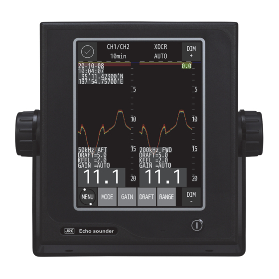
3. Display Mode 3.1 Standard mode Standard mode displays real time sounding echoes. [Sample screen at dual frequency] Display mode Depth display Date Time LAT/LON Range scale Frequency and position of transducer Explanation of depth Keel height value Gain control Depth Note ・... -
Page 36: History Mode
3.2 History mode History mode displays past 12hour, 24hour or 48hour depth graph and real time sounding. Display mode Depth display Time interval for History Time interval for real time display Date/time LAT/LON Position cursor data Depth History display area Real time display area Position cursor Keel height value... -
Page 37: Docking Mode
3.3 Docking mode Docking mode displays depth data. [Sample screen at dual frequency] Display mode Depth display Date/Time LAT/LON [AFT] Depth [FWD] Frequency Frequency Draft Draft Keel height Keel height Gain Gain Depth Note ・ LAT/LON display needs to input position data. 3. - Page 38 (Blank Page) 3. Display...
-
Page 39: Operation
4. Operation 4.1 Basic Operation Turning Power ON/OFF ・ To turn on power, press the button. ・ To turn off power, press the button. A confirmation screen whether to turn off the power will be displayed. Touch the ✓ button. Adjusting Control Panel Illumination [DIM+/DIM-] ・... -
Page 40: Gain Control [Gain]
Gain control [GAIN] ・ Gain can be set to 41 stages of 0~40. ・ Touch on top screen. The button color change to yellow green and gain menu is displayed. ・ Auto gain mode or manual gain value is displayed with red highlight on screen. ・... -
Page 41: Selecting Display Mode [Mode]
Selecting Display Mode [MODE] ・ Each time with touch, the display mode changes. Single frequency: Each time with touch, the display mode changes as follows. Standard mode: ↓ History mode: HIST_CH1 ↓ Docking mode: DOCKING ↓ Return to the Standard mode Dual frequency: Each time with touch, the display mode changes as follows. -
Page 42: Displaying Menu [Menu]
Displaying Menu [MENU] Displays the menu for setting various functions. ・ Touch and hold an item to select it, the item will turn yellow green. Items are selected by touch. ・ Select the required item to display the setting menu for that item. ・... -
Page 43: Right And Left Key Of Cursor [Cursor]
When it is a history mode ・ Whenever the is touched, the drawing time of the history is lengthened. (five stages of 3hr→6hr→12hr→24hr→48hr) ・ Whenever the is touched, the drawing time of the history is shortened. (five stages of 48hr→24hr→12hr→6hr→3hr) ... -
Page 44: Menu List
DEPTH ALERT LOST DEPTH WEAK ECHO TX F WEAK ECHO TXA WEAK ECHO RX F WEAK ECHO RX A NO PAPER LOST PRINT LOG MEMORY FAIL LOST PROC.(Only JFE-400) BUZZER TEST TRANSDUCER CODE INPUT *For service engineer menu 4. Operation... -
Page 45: Display Setting
4.3 Display Setting , the following menu will be displayed. ◎Touch ・ Select the required item to display the settings. ・ When is touched, return to previous menu ・ When is touched in each sub menu, selected content or setting value is registered in system. -
Page 46: Noise Rejection
Noise Rejection ◎The generation of this noise is decreased when a weak noise to the entire screen occurs and the screen is hard to see. ・ Touch and the settings will be displayed. Set content: 0/1/2/3/4/5/6/7/8/9/10 ・ Touch to increase the value and to decrease it. -
Page 47: Setting Cursor Display
Setting Cursor Display ◎The cursor display method in a standard mode and a history mode is selected. ・ Touch and the settings will be displayed. Set content: OFF/ON/AUTO OFF:The Depth cursor is not always displayed ON: The Depth cursor is always displayed. AUTO:... -
Page 48: Setting Depth Display
Setting Depth Display ◎The standard when the depth value is displayed is selected. ・ Touch and the settings will be displayed. Set content:SURF/KEEL/XDCR SURF:The record and the depth value in which the draft adjusted value is considered are displayed. KEEL:The record and the depth value in which the keel correction value is considered are displayed. -
Page 49: Switching The Display Color Mode Of The Day And Night Screen
Switching the display color mode of the day and night screen ◎Select a setting value to change the display color mode. ・ Touch and the settings will be displayed. Set content:DAY/DUSK/NIGHT DAY:Set the display color for daytime. DUSK : Set the display color of dim lighting such as early morning or evening. NIGHT:Set the display color scheme for night. -
Page 50: Setting Depth Alert
4.4 Setting Depth Alert , the following menu will be displayed. Depth where the depth alert starts is set. ◎Touch ・ Touch and the settings will be displayed. ・ Change the setting contents by entering a numerical value or ・ Depth can be set up to 99.9m by a 0.1m unit. ・... -
Page 51: Initial Setting
4.5 Initial Setting ・ Touch , the following menu will be displayed. ・ Select the required item to display the settings. ・ When is touched, return to previous menu Change screen color ◎Set the screen color of DAY/DASK/NIGHT ・ Touch and the following menu will be displayed ・... - Page 52 DAY ◎Set the color scheme when [DAY] is selected in the DAY/NIGHT settings. ・ Touch and the settings will be displayed. 7color + BLACK: Echo color is 7colors and screen is black. 7color + BLUE: Echo color is 7colors and screen is blue. 7color + WHITE:Echo color is 7colors and screen is white.
-
Page 53: Setting Adjustment Of Date And Time
Setting Adjustment of Date and Time ◎Date/Time/Time difference/GPS synchronization is set. ・ Touch and the following menu will be displayed. ・ Select the required item to display the settings. ・ When is touched, return to previous menu ・ When is touched in each sub menu, selected content or setting value is registered in system. - Page 54 DIFF (Time difference) ・ Touch and the setting will be displayed. ・ Touch to increase the value and to decrease it. ・ When the time difference is “±0", it is recognized as UTC. ・ After setting, touch FORMAT (Date display) ...
-
Page 55: Touch Panel Calibration
GPS SYNC (GPS synchronization) ・ Touch the settings will be displayed. Set content:OFF/ON OFF:An internal clock is used. ON:When an internal clock and the ZDA data have shifted for 30 seconds or more by using the ZDA sentence, an internal clock is corrected. ・... -
Page 56: Printer Control Setting(Option)
4.6 Printer Control Setting(Option) , the following menu will be displayed. ◎Touch ・ Select the required item to display the settings. ・ When is touched, return to previous menu ・ When is touched in each sub menu, selected content or setting value is registered in system. - Page 57 COPY: A present screen display is printed. The direction of paper feed is length against the screen. HISTORY:All the memorized depth data is graphically printed. The direction of paper feed is time. Secondary data is printed following primary in display screen for dual frequency. On single frequency mode, only displaying frequency data is printed.
- Page 58 2. HISTORY print mode 3. LOG print mode Depth data and graph 4. Operation 4-20...
-
Page 59: Setting Log Book Print
・ Change the settings with , ・ After setting, touch NOTE: When GPS position data is connected to JFE-400, LAT/LON position data would print. Setting Log Output Length ◎This item selects LOG output length on the HISTORY display mode with LOG print mode. -
Page 60: Checking System Version
4.7 Checking system version ◎ Internal software version and DSP version are displayed. ・ Touch and the software and DSP version will be displayed. ・ After confirming, touch 4.8 Initializing menu settings ◎Initialize user settings. ・ Touch and the confirmation screen will be displayed. ・... -
Page 61: Print Out Menu(Option)
4.9 Print out menu(Option) ◎ The contents are printed according to the printer settings(Refer to 4.6 printer control setting). ・ Touch and the confirmation screen will be displayed. ・ Touch to start printing. ・ Touch to return to the previous screen without printing. 4.10 SELF TEST , the following menu will be displayed. -
Page 62: Demo Mode
Demo Mode ◎ Execute demonstration. ・ Touch and the setting will be displayed. ・ Detail item :OFF/ON ・ Change the settings with , ・ Touch to start demonstration when setting is ON. The sounding function cannot be used while in demo mode. Self-test of Control Unit ◎... -
Page 63: Self-Test Of Lcd Unit
Self-test of LCD Unit ◎ Self-testing LCD Unit by displaying color pattern ・ Touch and the confirmation screen will be displayed. ・ Touch to start self-testing. ・ Color pattern(black->red->green->blue->white) is displayed with screenful. *When color pattern display is not correct, contact us or your agency. Self-test of Touch Panel ◎... -
Page 64: Self-Test Of Alert
Self-test of Alert Refer to 4.12 Alert Control for more details on each alert. ◎ Self-testing by simulating each alert. ・ Select the required item to display the settings. ・ When is touched, return to previous menu ・ When is touched in each sub menu, selected content. ・... - Page 65 Depth Alert ・ Touch and the setting will be displayed. ・ Detail item :OFF/ON ・ Change the settings with , ・ Touch to start simulating alert when setting is ON. Lost Depth ・ Touch and the setting will be displayed. ・...
- Page 66 WEAK ECHO TX A ・ Touch and the setting will be displayed. ・ Detail item :OFF/ON ・ Change the settings with , ・ Touch to start simulating alert when setting is ON. WEAK ECHO RX F ・ Touch and the setting will be displayed.
- Page 67 No Paper ・ Touch and the setting will be displayed. ・ Detail item :OFF/ON ・ Change the settings with , ・ Touch to start simulating alert when setting is ON. Lost Print ・ Touch and the setting will be displayed. ・...
-
Page 68: Self-Test Of Buzzer Test
Self-test of Buzzer Test ◎ Self-testing Buzzer. ・ Touch and the confirmation screen will be displayed. ・ Touch to start self-testing. *When buzzer does not sound, contact us or your agency. Self-test of TRANSDUCER Self-test of the transducer (CH1/CH2). Check (✓) that perform the check during the vessel is berthing. When the waveform after check becomes a chevron as shown in the figure below and OK is displayed in the lower left, there is no problem. -
Page 69: Displaying Of Equip Menu
4.11 Displaying of EQUIP menu , the following menu will be displayed. ◎Touch ・It is not a menu for users. ・Enter the password and touch to display the EQUIP menu on the main menu. ・ To return to the previous screen without entering the password, touch 4. -
Page 70: Alert Control
This section describes the types, displays, and settings of each alert. JFE-400/700 Echo Sounder displays alerts in accordance with IEC62923 Ed.1.0. Alert priority is defined as three types according to its priority and severity as shown in the table below. -
Page 71: Alert Icon And Status
Replace a processor unit Contact us or your agency Alert icon and status The icon of the alert changes depending on the situation and status. JFE-400/700 Echo Sounder uses the icons in the table below. Name of alert icon Functional outline... -
Page 72: Alert Display
Alert Display When an alert occurs, the alert message and icon are displayed at the top of the screen. After that, JFE-400/700 Echo Sounder can be operated by touching the screen as shown in the figure below. ● Alert Massage (ex; Depth Lost) ●... -
Page 73: Alert List Function
/ next page. ・ When is touched, return to previous menu. Alert History JFE-400/700 Echo Sounder can display a list of alerts that have occurred in the past. Touch , the Alert List screen will be displayed. ・ Touch to move to previous / next page . -
Page 74: Connecting With Cam System
CAM system. ● Alert silence from CAM The alert sound ringing on JFE-400/700 Echo Sounder can be silenced by operating on the CAM system. ● Alert ACK from CAM Applies to category –B alert in JFE-400/700 Echo Sounder. -
Page 75: Maintenance & Check
5. Maintenance & Check Do not open the equipment to inspect or repair internal circuits. Inspection or repairs by anyone other than a specialized technician may result in fire, electrical shock, or malfunction. If internal inspection or repair is necessary, contact our service center or agents. 5.1 Daily Maintenance The life of the equipment depends on the execution situation of the daily maintenance and check. -
Page 76: Maintenance Function
5.3 Maintenance Function Touch Panel Calibration Refer to "Touch Panel Calibration" in 4.5 Initial Setting. Displaying System No. Refer to 4.7 Checking system version. 5.4 Replacing Printer Paper (When NKG-901 printer is installed) Do not cut your hand in the blade tip of the paper cutter. Name Model type Remarks... -
Page 77: Troubleshooting
5.5 Troubleshooting The table below shows the principal symptom, the cause, and measurements. As a result, request the repair to our company or our agency when it is not possible to recover to normal operational condition. Symptom Cause Measurements The screen doesn't appear The breaker of AC100-230V of the ship is Make the breaker of AC100-230V of the ship even if power switch is... -
Page 78: Replacing Fuses
5.6 Replacing Fuses Exchange the fuse for the one of our specification. Exchange it after confirming the cause to which the fuse is blown. Moreover, turn off the main switch of the power supply CQD-2348 when you exchange fuses (Press ○ sign side). Model type Rating Remarks... -
Page 79: Consider Installation
6. Consider Installation • Do not install the JFE-400 where subject to the following conditions as such conditions may cause failures and reduce the life of the equipment. 1. Where liable to be splashed with water. 2. Where ventilation is poor. - Page 80 (Blank Page) 6. Consider Installation 6-6-2...
-
Page 81: After-Sales Service
Note that such inspection and maintenance is subject to charge. Please consult JRC or its agent for further details of any part of the after service conditions. Contact: See list at end of manual. - Page 82 If any failure occurs in the product during its normal operation in accordance with the instruction manual, the dealer or JRC will repair free of charge. In case that any failure is caused due to misuse, faulty operation, negligence or force major such as natural disaster and fire, the product will be repaired with charges.
-
Page 83: Disposal
8. Disposal Disposal of this equipment If this equipment is to be disposed, please follow the guidelines of the local body governing the location at which the equipment is disposed of. 8. Disposal... - Page 84 (Blank Page) 8. Disposal...
-
Page 85: Specifications
Power fail alert, Depth alert, System alert: (Relay contact output: rated load 120VAC 10A, 30VDC 8A, NO/NC) Specification:IEC61162-450 Transmission speed:10/100Mbps Data input/output :NMEA,IEC,JRC format IGMP snooping: IGMP v1, IGMPv2, IGMP v3 Temperature –15°C to +55°C / operating –25°C to +70°C / storage Humidity less than 93%RH under +40°C condition (non-condensing) - Page 86 (Blank Page) 9. Specification...
-
Page 87: Appendix
10. Appendix 10.1 Echo sample Noise Bubble Noise Bubble Interruption Interference Noise from other ship Plankton layer 10.Appendix 10-1... - Page 88 Actual Pictures Zero line DISP TRANS figure A Seabed DISP SURF DISP KEEL Seabed Zero line Third reflection of bottom Second reflection of bottom Seabed In case of a shallow seabed or when increasing the amplifier sensitivity, two seabed lines may be recorded.
- Page 89 Seabed Quality Change Rock In case of a hard seabed composed of rocks etc., its return trails long, as shown in right chart. In case of a soft seabed made of mud, seaweed, etc., they poorly reflect an ultrasonic wave to result in thin recording of the seabed with short trail.
- Page 90 In either case, the dim or thin echoes are false and produced by side lobes of ultrasonic beam from the transducer. Any false echo is thinner than and parallel to a real echo. The echo of a seabed with abrupt slope is recorded as a lone difficult to see and less discriminative, since it tends to accompany with a false echo due to the side lobe and the inherent property of directivity.
-
Page 91: Data Format
10.2 Data Format 1.List of Handling Sentence Data Sentence Description Message Type Direction Interface Depth Output LAN & Serial Depth below transducer Output LAN & Serial Depth below keel Output LAN & Serial Depth below surface Output LAN & Serial PJRCU Depth relative to transducer Output... - Page 92 3) DBK – Depth below keel $--DBK, x.x, f, x.x, M, x.x, F*hh<CR><LF> 1: Water depth, feet 2: Water depth, meters 3: Water depth, fathoms 4) DBS – Depth below surface $--DBS, x.x, f, x.x, M, x.x, F*hh<CR><LF> 1: Water depth, feet 2: Water depth, meters 3: Water depth, fathoms 5) PJRCU –...
- Page 93 8) ALC – Cyclic alert list $--ALC,xx,xx,xx,x.x,aaa,x.x,x.x,x.x,……..,aaa,x.x,x.x,x.x*hh <CR><LF> 1 2 3 4 5 6 7 8 9 10 1: Total number of sentences for this message, 01 to 99 1 2: Sentence number, 01 to 99 1) 3: Sequential message identifier, 00 to 99 2) 4: Number of alert entries 3) 5: Manufacturer mnemonic code 6: Alert identifier...
- Page 94 Alert priority and Alert state can be null fields. 2) The sequential message identifier relates all sentences that belong to a group of multiple sentences (i.e. message). Multiple sentences with the same sequential message identifier, make up one message. 3) Time should represent the last time the data within the alert message has changed. For example changing the alert text by in-/decrementing a contained counter or count down should cause a revision of alert message and a new time.
- Page 95 identifier). It is not permitted to modify the alert instance within a life cycle of a distributed alert (from ‘active and unacknowledged’ state until ‘normal’ state is reached). It can be also a null field, when there is only one alert of that type. 10) The revision counter is the main method to follow up-to-date status.
- Page 96 4) The alert instance identifies the current instance of an alert to distinguish alerts of the same type (Alert identifier) and from the same source (e.g. dangerous target). Alert instance is maximum a 6-digit integer from 1 to 999999. The number of alert instance can be freely defined by the manufacturer as long as it is unique for one type of alert (alert identifier).
- Page 97 had determined for the corresponding indicator value. If the equipment had no brightness or dimming preset capability this field would be ignored. 2) The brightness percentage field contains a value from zero to ninety nine. The value zero, provided as 00, indicates that the display’s brightness should be set to its most dimmed level, as determined by the capabilities of the equipment.
- Page 98 This field can be used to indicate the current equipment status. This could be the result of an built-in integrity testing function. 3) The sequential sentence identifier provides a message identification number from 0 to 9 that is sequentially assigned and is incremented for each new sentence. The count resets to 0 after 9 is used.
- Page 99 selected accuracy level corresponding to the actual navigation mode, and/or integrity is available but exceeds the requirements for the actual navigation mode, and/or a new valid position has not been calculated within 1 s for a conventional craft and 0,5 s for a high speed craft.V = Navigational status not valid, equipment is not providing navigational status indication.
- Page 100 S = Simulator N = Data not valid 2) The mode indicator field supplements the status field (field 6). The status field should be set to V = invalid for all values of operating mode except for A = Autonomous and D = Differential. The positioning system mode indicator and status fields should not be null fields.
- Page 101 4) The alert instance identifies the current instance of an alert to distinguish alerts of the same type (Alert identifier) and from the same source (e.g. dangerous target). Alert instance is maximum a 6-digit integer from 1 to 999999, the number ‘0’ indicates that the command is intended for all alert instances.
- Page 102 (Blank Page) 10.Appendix 10-16...
- Page 104 アスベストは使用しておりません Not use the asbestos For further information,contact: Since 1915 URL Head office: http://www.jrc.co.jp/eng/ Marine Service Department 1-7-32 Tatsumi, Koto-ku, Tokyo 135-0053, Japan e-mail : tmsc@jrc.co.jp One-call : +81-50-3786-9201 ISO9001, ISO14001 Certified. CODE No.7ZPNA2051 MAR. 2021 1 Edition...
Need help?
Do you have a question about the JFE-400 and is the answer not in the manual?
Questions and answers
How to input keel value
To input the keel value for the JRC JFE-400:
1. Touch the display to open the settings.
2. Select the depth display standard setting.
3. Choose "KEEL" to use the keel correction value for depth display.
4. Adjust the keel value using the arrow buttons.
5. After setting, touch the confirmation button to save.
This sets the depth display to show depth relative to the keel.
This answer is automatically generated