Table of Contents
Advertisement
Advertisement
Table of Contents

Subscribe to Our Youtube Channel
Related Manuals for JRC JFC-130


Summary of Contents for JRC JFC-130
- Page 1 COLOR ECHO SOUNDER INSTRUCTION MANUAL...
-
Page 3: Preface
Preface Thank you for purchasing our JRC JFC-130/130HP color echo sounder . This unit displays schools of fish by color video. · This unit i4s for detecting schools of fish. Before attempting to operate it, read this instruction manual thoroughly to correctly and safely operate this unit in accordance with the warning instructions and operation procedures in this manual. -
Page 4: Before Operations
Before Operations Pictorial Indication Various pictorial indications are included in this manual and are shown on these equipment so that you can operate them safely and correctly and prevent any danger to you and/or to other persons and any damage to your property during operation. Such indications and their meanings are as follows. -
Page 5: Precautions Upon Equipment Operation
Precautions Upon Equipment Operation Do not remove the cover of this set. Otherwise, you may touch a high-voltage part and suffer from an electrical shock. Do not disassemble or modify this set. Otherwise, a fire, an electrical shock, or a failure may occur. - Page 6 Do not damage, break or modify the power cord. When a heavy object is placed on the cord or the cord is heated, pulled, or forcibly bent, the cord will be broken resulting in a fire or an electrical shock. Do not use this set at a voltage other than the supply voltage stated on the set.
- Page 7 Please assign the electrical work for the set to our sales department, our branch or marketing office that is nearest to you. Any electrical work by any person other than our specialized maintenance persons may cause malfunction of this set. Do not use or leave alone this set at any place where the LCD monitor is exposed to direct sunlight for a long time or the temperature rises...
- Page 8 Do not turn on the power switch of the set while the ship is on the shore. Otherwise, the transducer may be broken. When removing the power cord, be sure to remove the power cord terminal correctly. If the power cord is pulled, the cord may be damaged resulting in a fire or an electrical shock.
-
Page 9: Emc Installation & Service Guidelines
EMC Installation & Service Guidelines IMPORTANT NOTE All JRC equipment and accessories are designed to the highest industry standards for use in a leisure marine environment. Their design and manufacture conforms to the appropriate Electromagnetic Compatibility (EMC) standards, but good installation is required to ensure that performance is not compromised. Although every effort has been taken to ensure that the equipment will perform under all conditions, it is important to understand what factors could affect operation of the product. -
Page 10: Suppression Ferrites
Servicing · JRC equipment should be serviced only by authorized JRC service engineers. They will ensure that service procedures and replacement parts used will not affect performance. There are not user serviceable parts in any JRC product. · Always report any EMC related problem to your nearest JRC dealer. We will use any such information to improve our quality standards. -
Page 11: Notes For Using The Echo Sounder
Notes for Using the Echo Sounder · The life of the echo sounder depends on the hours of use. Put the device on the rest even during a short time by turning off the power switch every time the set is unused. ·... -
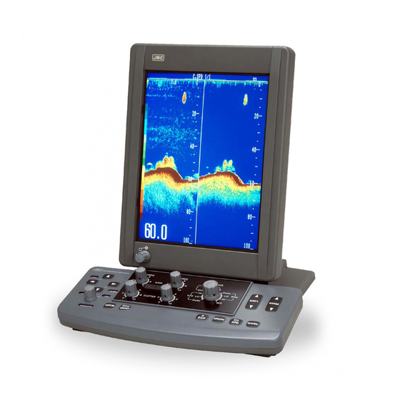
Page 12: Outside View
Outside View Outside View of the JFC-130/130HP (Vertical mount) Outside View of the JFC-130/130HP (Horizontal mount) Outside View... -
Page 13: Table Of Contents
Contents Preface ..........................i Before Operations ......................ii Precautions Upon Equipment Operation..............iii EMC Installation & Service Guidelines................vii Notes for Using the Echo Sounder ................ix Outside View ........................x Glossary of Terms ......................xvi SECTION 1 Introduction....................1 1.1 Function.............................1 1.2 Features .............................2 1.3 Components ............................3 1.4 Structure ............................4 1.5 Power and Transducer Connection ....................5 SECTION 2 Names and Functions of Components............6... - Page 14 MIXED mode ..........................11 A-scope display ..........................11 Menu Displays..........................12 3.2 Basic Operations ........................... 13 Turning the Power On and Off ([POWER] switch)................ 13 Adjusting Brightness ([Brightness] control) ................13 DAY/ Switching Brightness between Day and Night ( key) ............13 NIGHT Selecting Display Modes([MODE] switch) ..................
- Page 15 Choosing from among five bottom discrimination range............. 23 Varying a preset bottom discrimination mode range............23 Shift Operations..........................24 SHIFT Shifting a Range ( key) ..................... 24 SHIFT Screen Display Operations......................24 Repositioning/Hiding the Water Temperature Display (TEMP.POSITION) ........24 Canceling Interfering Signal (INTERFERENCE) .................
- Page 16 Rejecting Particular Colors (COLOR REJ.) ................. 40 Discriminating between the Sea Bottom and Fish Schools (WHITE LINE) ......... 41 Suppressing Interference (ADJUST FREQ.)................42 Getting Sharper Display Pictures (TX PULSE WIDTH) ............... 42 Preventing interruption by Bubble (TX CYCLE MODE) ............... 43 To inhibit the display of the quasi sea-bottom image (ADJUST TX CYCLE) .......
- Page 17 SECTION 7 Disposal....................59 SECTION 8 Index ......................60 SECTION 9 Specifications ..................62 Contents...
-
Page 18: Glossary Of Terms
Glossary of Terms The front of a vessel (nautical term). Cavitation Air bubbles in the water which affect the echo level measured by a transducer normally caused by mounting the transducer at an incorrect angle or location. Chart speed The rate at which echoes scroll across the display. The higher the chart speed, the clearer the picture. -
Page 19: Section 1 Introduction
Function The color echo sounder JFC-130/130HP is a device, where the transducer mounted on the bottom or side of the hull emits ultrasonic waves toward the sea bottom and catches the waves reflected from the fish under the ship so as to find fish. -
Page 20: Features
· A narrow zero line feature, coupled with a new transducer, narrows oscillation lines, to clearly monitor small fish schools near the sea surface through high-speed transmissions at a rate of up to 600(JFC-130)/300(JFC- 130HP) cycles per minute. The BOTTOM LOCK EXPAND mode with 16-halftone colors precisely discriminates between the sea bottom and bottom fish schools. -
Page 21: Components
Components When unpacking your JFC-130/130HP, you should find the following standard equipment in the carton. If any items are missing, please notify your JRC dealer immediately. (1) Standard Equipment JFC-130 Description Model No. Remarks packing Display unit NWZ-146 Display unit... -
Page 22: Structure
Structure 4-M4 DEPTH 6 (unit: mm) Outline dimensions NWZ-146 display unit (vertical mount) (horizontal mount) 4-M4 DEPTH 6 (44.6) 5゚ (unit: mm) Outline dimensions NCH-562 keyboard unit (unit: mm) Outline dimensions NJH-1130/NJH-1130HP Introduction... -
Page 23: Power And Transducer Connection
Power and Transducer Connection NWU-146 display unit NCH-562 keyboard unit CFQ-6900 CFQ-6901 power cable video cable attached cable TRANSDUCER B CONNECTOR Mono frequency / Low frequency transducer NJA-1130/1130HP Cable Pin Number processing unit White Shield Black HS21P-3 P/N 5JCAA00020 HS21P-5 Low frequency transducer P/N 5JCAA00011 (75kHz, 50kHz, 38kHz,28kHz) -
Page 24: Section 2 Names And Functions Of Components
SECTION 2 Names and Functions of Components The names and functions of the components of the JFC-130/130HP color echo sounder are shown below. Disp la y u nit ● Brightness Adjust brightness. ●Keyboard unit Detailed names and functions, Power switch ●... - Page 25 Pr o c ess in g u ni t ●VIDEO DC OUT ● KEYBOARD Power supply for NWZ-146. Connect keyboard unit. Connect to NWZ-146 only. ●TRANSDUCER B ● Low frequency REMOTE CONTROL transducer Connect remote controller (option). ●TRANSDUCER A or A/B High frequency ●...
-
Page 26: Keyboard Unit Keys
< Keyboard unit keys ⑬ ⑪ ⑨ ⑧ ② ① ⑭ ⑫ ⑦ ⑩ ⑥ ⑤ ④ ③ Names and Functions of Components... -
Page 27: Keyboard Unit Keys And Functions
< Keyboard unit keys and functions Keys Functions Keys Functions ① ⑨ RANGE GAIN Change a display range one level Adjusts the gains for both at a time high and low frequencies. ⑩ CLUTTER Suppress the noise across the ② SHIFT Move the shift (upper-most depth screen for both high and low... -
Page 28: Section 3 Operation
SECTION 3 Operation Screen layout Fishfinding Displays Ultrasonic signals transmitted from the Interference rejection level Time Mark transmitter/receiver at the bottom of the Chart speed Depth unit boat are reflected upon the underwater Water temperature plankton, fish schools, and sea bottom Weak Depth scale and are received by the transmitter/... -
Page 29: Bottom Lock Expand Mode
< BOTTOM LOCK EXPAND mode Split display of a standard Low- and high-frequency (Keyboard unit⑧, see page 8) display and a expanded split display bottom display Three kinds of display are selectable: a split display of a standard display and a expanded bottom display, a low- and high-frequency split display, and a frequency specific expanded bottom display. -
Page 30: Menu Displays
Menu Displays The four menu displays available are the main menu, the fishfinding menu, the record/replay menu, and the custom menu. 1.PRESET STD RANGE ≫ 1 2 3 4 5 6 7 8 9 10 RANGE 60 80 100 150 200 11... -
Page 31: Basic Operations
Basic Operations Turning the Power On and Off ([POWER] switch) When turning on the power, be sure not to press any operator panel key at the same time. Alternates hardware configuration of the until could cause the unit to malfunction. Turn the [... -
Page 32: Changing The Chart Feed Speed
Changing the Chart Feed Speed ( key) Each time you press the key, the chart feed speed changes from 1/1 to 1/2, to 1/3, to 1/4, to 1/5, to 1/6, to 1/7, to 1/8, to 1/9, and to -/- (off). Continue pressing the key and the feed will stop at the stop position once. -
Page 33: Calling Up The Main Menu ( + Key)
Calling up the Main Menu ( key) To call up the main menu, press the keys at the same time. 1.PRESET STD RANGE ≫ 1 2 3 4 5 The main menu provides a listing of 11 setup items. Press the 6... -
Page 34: Calling Up The Fishfinding Menu ( + Key)
Calling up the fishfinding menu ( key) Calling up the fishfinding menu, press the keys at the same 1.COLOR REJ. ≫ time. 2.WHITE LINE ≫ LO FRQ OFF HI FRQ OFF 3.ADJUST FREQ. ≫ LO FRQ 50.0 HI FRQ 200.0 The fishfinding will then appear onscreen, proving a listing of 12 setup 4.TX PULSE WIDTH LONG SHORT... -
Page 35: Resetting To Prerecorded Settings
Resetting to Prerecorded Settings ( key) CUSTOM When you have inadvertently performed an incorrect operation or made an invalid setting, you can easily reset them to their original status (prerecorded setting). To reset to prerecorded settings, follow these steps: Press the CUSTOM key to call up the CUSTOM MENU. -
Page 36: Key Lock Function
DAY/ Key lock function ( key) MARK NIGHT The key input for displaying the menu may be made invalid. (This function is called “Key lock.”) To set/release a key lock, operate as follows: DAY/ When the key and key are pressed simultaneously, a key MARK NIGHT lock is set and a “key hole”... -
Page 37: Function Key Operations
Function Key Operations Range Operations RANGE < Changing a Range ( key) RANGE (1)Standard range display Reduce the preset range level. RANGE PRESET RANGE Increment the preset range level. Manual Makes the range shallow. RANGE STEP RANGE Deepens the range. AUTO Range are changed automatically according to changes in water depth. -
Page 38: Varying A Range Automatically (Auto)
< Varying a Range Automatically (AUTO) 1.PRESET STD RANGE ≫ 1 2 3 4 5 You can have a range varied automatically to display the sea bottom at all 6 7 8 9 10 RANGE 60 80 100 150 200 RANGE 11... -
Page 39: Varying The Vrm Expand Mode Range (Vrm Exp. Range)
< Varying the VRM EXPAND Mode Range (VRM EXP. RANGE) The VRM EXPAND mode range is selectable from five preset choices. 1.PRESET STD RANGE ≫ 1 2 3 4 5 These five presets may be varied as desired (in range of 1 to 100). 6... -
Page 40: Varying The Bottom Lock Expand Mode Range (Btm Exp.range)
< Varying the BOTTOM LOCK EXPAND Mode Range (BTM EXP.RANGE) The BOTTOM LOCK EXPAND mode range is selectable from five preset 1.PRESET STD RANGE ≫ 1 2 3 4 5 choices. These five presets may be varied as desired (in a range of 1 to 50). 6... -
Page 41: To Change The Display Range Of The Sea-Bottom Image Portion (B.discrim Range)
< To change the display range of the sea-bottom image portion (B.DISCRIM RANGE) Changing of the display range of the sea-bottom image portion is performed by selecting “bottom discrimination range” on the main menu. There are two methods for changing: one is to select one of the five preset 1.PRESET STD RANGE ≫... -
Page 42: Shift Operations
Shift Operations SHIFT < Shifting a Range ( key) SHIFT SHIFT Press the keys to shift display range up and down. Each SHIFT SHIFT time you press the key, the range is shifted, one level at a SHIFT time. SHIFT Press the key to shift up or the key to shift down. -
Page 43: Canceling Interfering Signal (Interference)
< Canceling Interfering Signal (INTERFERENCE) An interference canceler is available to cancel interfering signals coming 1.PRESET STD RANGE ≫ 1 2 3 4 5 from fishfinders mounted on other boats. The interference canceler has four 6 7 8 9 10 settings: OFF, 1, 2, and AUTO. -
Page 44: Changing Depth Scale Divisions (Fine Scale)
< Changing Depth Scale Divisions (FINE SCALE) You can change the divisions of the depth scale appearing onscreen. Normally, set the divisions to AUTO. To change depth scale divisions, follow these steps: 1.PRESET STD RANGE ≫ 1 2 3 4 5... -
Page 45: Displaying/Hiding The Cursor (Vrm)
< Displaying/Hiding the Cursor (VRM) The cursor appearing onscreen can be hidden as needed. 1.PRESET STD RANGE ≫ 1 2 3 4 5 To display or hide the cursor, follow these steps: 6 7 8 9 10 RANGE 60 80 100 150 200 11... -
Page 46: Repositioning/Hiding The Bottom Depth Display (Depth Position)
< Repositioning/Hiding the Bottom Depth Display (DEPTH POSITION) The depth display appears onscreen. If its position interferes with the sight 1.PRESET STD RANGE ≫ 1 2 3 4 5 of the display image, you can reposition or hide its display. 6... - Page 47 Split display mode SPLIT DISP.MODE MODE High-Freq. Low- High- DUAL Freq. Freq. Low-Freq. 1-Freq. Low- High- Freq. Freq. DUAL Exp. Exp. ZOOM 1-Freq. 1-Freq. Exp. Exp. Freq. Freq. Expanded Expanded Low- High- Low- High- Freq. Freq. Freq. Freq. DUAL B tm .- B tm .- Exp.
-
Page 48: Bottom Discrimination Display Mode
< Bottom discrimination display mode Generally speaking, the sweep width varies as shown below depending on 1.PRESET STD RANGE ≫ 1 2 3 4 5 the Bottom discrimination. 6 7 8 9 10 RANGE 60 80 100 150 200 11 12 13 14 15 Type of bottom material Tail width 250 300 400 500 800... -
Page 49: Changing The Mode Of A-Scope Display(A-Scp Mode)
< Changing the Mode of A-Scope Display(A-SCP MODE) 1.PRESET STD RANGE ≫ 1 2 3 4 5 You can choose from two alternative modes of A-scope display: log and 6 7 8 9 10 linear to suit specific needs. RANGE 60 80 100 150 200 11... -
Page 50: Color Operations
Color Operations < Changing the Background Color (BACK COLOR) You can choose the background color of your fishfinding display from four choices. 1.PRESET STD RANGE ≫ 1 2 3 4 5 To change the background color, follow these steps: 6 7... -
Page 51: Customizing Colors To Be Used (User Color)
< Customizing Colors to be Used (USER COLOR) While the signal level colors and the background color of your fishfinding display are selectable from four choices, you may customize these colors at your option. Colors are composed of a mixture of R, G, B, or red, green, and blue. -
Page 52: Graph Operations (Set Graph)
Graph Operations (SET GRAPH) < Changing the Display Time The graph display time is selectable from among 1 hour, 2 hours, and 3 1.PRESET STD RANGE ≫ 1 2 3 4 5 hours. 6 7 8 9 10 RANGE 60 80 100 150 200 Water temperature and depth data is stored in memory even while 11... -
Page 53: Changing The Depth Range
< Changing the Depth Range You can change the water depth range (upper and lower limits) for display in 1.PRESET STD RANGE ≫ 1 2 3 4 5 a graph. Water depths can be set in a range of 0 to 2,000m. 6... -
Page 54: Unit Set Up Operations (Unit)
Unit Set up Operations (UNIT) < Changing the Depth Unit (DEPTH UNIT) 1.PRESET STD RANGE ≫ 1 2 3 4 5 Three depth units are available for selection: the meter, feet, fathom, and 6 7 8 9 10 special. The special unit is a user-defined unit. RANGE 60 80 100 150 200 11... -
Page 55: Displaying The Depth From The Keel (Below Keel)
< Displaying the depth from the keel (BELOW KEEL) 1.PRESET STD RANGE ≫ 1 2 3 4 5 If you set the keel height of your boat as a keel height correction value, you 6 7 8 9 10 can display the depth from the keel to the sea bottom as a water depth. RANGE 60 80 100 150 200 11... -
Page 56: Fishfinding Display Operations
Fishfinding Display Operations < Adjusting Gains l Adjusting Gains with the [GAIN] Control Two [GAIN] controls are available, one for adjusting the high-frequency receiver gain and the other for adjusting the low-frequency receiver gain. Turn the [GAIN] controls to adjust the display screen gains for the corresponding group of frequencies. -
Page 57: Adjusting Nearby Gains By Setting The Stc Adjust
l Adjusting Nearby Gains by Setting the STC ADJUST The STC ADJUST menu control the gains of 3 feet (1 meter) below the transducer. This is effective with the transducer type CFT-2505KD. With other transducer, normally set the value to 0. To change the STC ADJUST, follow these steps: Press the MARK... -
Page 58: Rejecting Particular Colors (Color Rej.)
< Rejecting Particular Colors (COLOR REJ.) You can reject particular colors regardless of the gain, clutter, and STC settings. Using this function, you can reject colors that represent weak signals to suppress noise or unwanted fish school views from the screen. To reject particular colors, follow these steps: Press the keys at the same time to call up the... -
Page 59: Discriminating Between The Sea Bottom And Fish Schools (White Line)
< Discriminating between the Sea Bottom and Fish Schools (WHITE LINE) You can reject signals (colors) in the order of descending signal intensity to discriminate between the sea bottom and fish schools or determine the volume of a fish school. To monitor fish groups on and around the sea bottom, set the white line to erase the strongest signal that represents the sea bottom (reddish brown). -
Page 60: Suppressing Interference (Adjust Freq.)
< Suppressing Interference (ADJUST FREQ.) When the approach of other boats or the engine noise from your own boat gives interference to the screen beyond correction by the technique introduced earlier, they can be suppressed by fine-tuning the transmitter frequency. See page 25 “Canceling Interfering Signals (INTERFERENCE).” Adjust frequency in a range of ±10kHz at 200kHz and 75kHz, or a range of ±5kHz at 50kHz, 38kHz, and 28kHz. -
Page 61: Preventing Interruption By Bubble (Tx Cycle Mode)
< Preventing interruption by Bubble (TX CYCLE MODE) The transmission cycle and the chart feed timing are normally synchronized with each other, but they can be unsynchronized to make the sounder more resistant to the interruption by bubble. Remember, however that in shallow seas this setting is prone to pick quasi sea-bottom echo. -
Page 62: Darkening/Lightening General Colors (Adc Mode)
< Darkening/Lightening General Colors (ADC MODE) Changing the ADC mode makes the entire fishfinding display colors look darker or lighter. To change the ADC mode, follow these steps: Press the keys at the same time to call up the 1.COLOR REJ. ≫... -
Page 63: Emphasizing Little Echoes Onscreen 1 (Sig.process)
< Emphasizing little Echoes Onscreen 1 (SIG.PROCESS) When a response is so little that it is hardly distinguishable, use the signal processing feature to display the echoes emphasized in the vertical direction. The signal processing has three settings: OFF, 1, and 2. “1” provides the lowest degree of emphasis, while “2”... -
Page 64: Error Messages
Error Messages When the following error messages are displayed, take corrective action as suggested. < CAN’T BACK UP The current settings could not be recorded for some reason. 正常にバックアップ出来ません! l Action CAN’T BACK UP ! Error message Turn off the echo sounder, and turn on again after several seconds. If the echo sounder still works no good, call the distributor, office, or dealer from whom the instrument was purchased. -
Page 65: Executing A Master Reset
< Executing a Master Reset A master reset initialize the data memory in processor. And the transducer setting is needed. Never execute a master reset if you do not know the installed transducer type. To execute master reset, follow these steps: Turn the [POWER] off. -
Page 66: Remote Controller Functions
▲ SHIFT keys ▼ SHIFT If you are a JFC-130/130HP user, use these keys to shift a display range up ▲ SHIFT and down. Each time you press the key, the range is shifted, ▼... - Page 67 This key stops an audible alarm when it sounds. It is also used to set the record/replay function and the alarm function of the remote controller. This key calls up the ALARM menu for enabling or disabling the audible alarm. It also exits the ALARM menu to the fishfinding display. This key calls up the RECORD PICTURE menu for recording display images.
-
Page 68: Remote Controller Operation
Remote Controller Operation Record/Replay Function Using the record/replay function, you can record up to two of the images appearing in the right-hand side of the screen. You can replay the recorded images anytime. The recorded images are lost when the power is turned off <... -
Page 69: Replaying A Recorded Image
< Replaying a Recorded Image You can display a recorded image, which appears in the right-hand side of the screen. No menus and graphs can be displayed while a recorded image is being replayed. To replay a recorded image, follow these steps: Press the key to call up the REPLAY PICTURE menu. -
Page 70: Alarm Function
Alarm Function Using the alarm function makes it possible to sound an alarm tone (fish school alarm) when a preset range of fish school responses is encountered or sound an alarm tone (water-temperature alarm) when a preset range of water temperatures is reached. -
Page 71: Setting The Fish School Alarm
< Setting the Fish School Alarm You can sound an alarm tone when a fish school response having a signal level higher than specified is encountered within a specified range. Use the FISH ALARM menu to set a fish school alarm range and a signal level. A fish school alarm range up to 2000 (in meter terms) from the zero line can be set. -
Page 72: Setting The Water Temperature Alarm
< Setting the Water Temperature Alarm You can sound an alarm tone when a preset range of water temperature is reached. Use the TEMP ALARM menu to set a water temperature alarm range. Water temperature within a range of 14°F(-10°C) to 122°F (+50°C) can be set. -
Page 73: Section 4 Maintenance
SECTION 4 Maintenance There are no customer-serviceable parts inside. Unauthorized inspections and repairs could cause fires and electrical shock hazards. Please call our field representative or your nearest JRC office for inspection and repair services. CAUTION When cleaning the surface, do not use any organic solvent such as thinner or benzene. Otherwise, the painting on the surface may be damaged. -
Page 74: Measures To Be Taken When An Abnormality Or Failure Has Been Found
Measures to be taken when an abnormality or failure has been found When one of the following symptoms appears, stop operation and contact the dealer or agent from Which you purchased the device or one of our branches, marketing offices, and representative offices. (1)The screen does not become bright. -
Page 75: Section 5 Consider Installation
SECTION 5 Consider Installation Avoid the installation of this set in one of the following places. Otherwise, a failure will occur or the life of the set will be shortened. 1. A place exposed to direct sunlight The LCD will deteriorate promptly. 2. -
Page 76: Section 6 After-Sales Service
SECTION 6 After-Sales Service When ordering a repair When a failure has been detected, stop operation and contact the dealer or agent from which you purchased the device or one of our branches, marketing offices, and representative offices. · Any repair during the warranty period will be performed by the dealer or our company without any charge according to the provisions in the specific action. - Page 77 SECTION 7 Disposal When despising this set, process it in accordance with the rules of the pertinent local government. For details, please contact the dealer from which you purchased the device, our marketing office that is nearest to you, or the pertinent local government.
- Page 78 Index This section of the manual gives a listing of the topics and the numbers of the pages to consult when you want to Know more about particular aspects of the JFC-130/130HP color echo sounder operation. Ranges Change a range ・・・・・・・・・・・・・・・・・・・・・・・・・・・ 19 Vary a range automatically ・・・・・・・・・・・・・・・・・・...
- Page 79 Menu Selections Call up the main menu ・・・・・・・・・・・・・・・・・・・・・ 15 Hide the main menu and display a fishfinding display ・ 15 Hide the submenu and display a fishfinding display ・・・ 15 Fishfinding Displays Exit the submenu to the main menu ・・・・・・・・・・・ 15 Call up the recording menu ・・・・・・・・・・・・・・・・・・...
-
Page 80: Specifications
1.999 m) selectable Color rejection Set on menu displays. Display mode Mode select rotary switch, Frequencies 200, 75, 50, 38, and 28kHz graph key, A-scope key Transmitter output JFC-130: Standard High-/low-/dual-frequency JFC-130HP: 3kW Standard and VRM High-/low-/dual-frequency FM transmission 200kHz... - Page 82 HEAD OFFICE & Nittochi Nishi-Shinjuku bldg. SALES DEPT 10-1,Nishi-Shinjuku 6-chome, Shinjuku-ku, Tokyo.160-8328 JAPAN Phone : +81-3-3348-0151 : +81-3-3348-3648 1-1, Shimorenjaku 5-chome, Mitaka-shi MAIN PLANT Tokyo.181-8510 JAPAN Phone : +81-422-45-9111 : +81-422-45-9110 DC50-JFC-130 CODE No. 7ZPBS2506...
Need help?
Do you have a question about the JFC-130 and is the answer not in the manual?
Questions and answers
Change from feet to fathams