Sign In
Upload
Download
Table of Contents
Contents
Add to my manuals
Delete from my manuals
Share
URL of this page:
HTML Link:
Bookmark this page
Add
Manual will be automatically added to "My Manuals"
Print this page
×
Bookmark added
×
Added to my manuals
Manuals
Brands
JRC Manuals
Marine Equipment
JLR-7900
Quick reference
JRC JLR-7900 Quick Reference
Multi information display, doppler log, gps navigator
Hide thumbs
1
2
3
4
5
6
7
8
9
10
11
12
13
14
15
16
17
18
19
20
21
22
23
24
25
26
27
28
29
30
31
32
33
34
35
36
37
38
39
40
41
42
43
44
45
46
47
48
49
50
51
52
53
54
55
56
57
58
59
60
61
62
63
64
65
66
67
68
69
70
71
72
73
74
75
76
77
78
79
80
81
82
83
84
85
86
87
88
89
90
91
92
93
94
95
96
97
98
99
100
101
102
103
104
105
106
107
108
109
110
111
112
113
114
115
116
117
118
119
120
121
122
123
124
125
126
127
128
129
130
131
132
133
134
135
136
137
138
139
140
141
142
143
144
145
146
147
148
149
150
151
152
153
154
155
156
157
158
159
160
161
162
163
164
165
166
167
168
169
170
171
172
173
174
175
176
177
178
179
180
181
182
183
184
185
186
187
188
189
190
191
192
193
194
195
196
197
198
199
200
201
202
203
204
205
206
207
208
209
210
211
212
213
214
215
216
217
218
page
of
218
Go
/
218
Contents
Table of Contents
Troubleshooting
Bookmarks
Table of Contents
English
Before You Begin
Usage Hints
External View
Table of Contents
Section 1 Introduction
Function
Feature
Components
Standard Equipments
Options
Construction
System Configuration
Section 2 Names and Functions of the Components
NWZ-4610 Display Unit
Section 3 Display Screen
Display Screen
Section 4 Operation
Basic Operation
Turning on the Power
Starting (Normal)
Starting (Abnormal-1)
Starting (Abnormal-2)(GPS)
Starting (Abnormal-3)
Turning off the Power
Adjusting the Back Light (Lighting) by Using the Key
Adjusting Contrast
Turning off the Alarm Buzzer
Alarm Display
Switching Display (Automatic)
User Mode Change (MID)
User Setting Screen Display (MID)
Resetting a TRIP (LOG)
Changing a Unit of the Vessel Speed (LOG)
Selecting a Waypoint/Route with the GOTO Key (GPS)
Mob (Gps)
Registering the Own Ship's Position (GPS)
Menu Operation
Selecting Items from the Menus
Entering a Numeric Value
Changing to a Maintenance Mode
Setting a Model
Menu List
Display Category and Contents
Section 5 Maintenance
Daily Maintenance
Alarm
Troubleshooting for Malfunction or Abnormalities
Troubleshooting
Repair Unit
Regular Replacement Parts
Section 6 Installation
Affixing Display Unit Nameplate Labels
Display Unit Installation
Selecting the Position for Installation
Mounting the Display Unit Using a Rack
Mounting Using a Flush Mount
Removing the Display Unit by Flush Mounting
GPS Sensor Installation
Selecting the Position for Installation
Sensor Installation Procedure
Installation of the Sensor on the Mast
Doppler Log Installation
Cable Connection
DC12/24V DATA Connector
DATA1 Connector
SENSOR/DATA2 Connector (MID/GPS)
Optional Peripheral Connection
Dimmer Unit Connection
When Ordering a Repair
Recommendation of Overhaul
Section 7 after Service
Repair Parts Stocking Period
Warranty
Section 8 Disposal
Disposal of the Equipment
Disposal of Used Batteries
Section 9 Specification
Display Unit
Doppler Log
JLR-4341 DGPS Sensor
JLR-4341 GPS Sensor
日本語
第1章 装置のあらまし
標準構成
オプション
総合系統図
第2章 各部の名称とはたらき
Nwz-4610 表示器
第3章 表示画面
表示画面
第4章 操作方法
基本操作
電源の投入
起動(正常
起動(異常
起動(異常)(Gps)
バックライトの調節
起動(異常
電源の切断
アラームの表示
アラームブザーの停止
コントラストの調節
画面を切り替える
画面を切り替える(自動
利用モードを切り替える(MID
ユーザ画面に切り替える (MID)
区間航程距離(コウテイ)をリセットする(Log
船速単位を切り替える(Log
Goto キーで目的地/航路を選択する(Gps
Mob 機能を実行する (Gps)
自船位置を登録する (Gps)
メニュー内の設定をする
メニュー操作
数値を入力する
メンテナンスモードへ移行する
機種設定を行う
第5章 保守・点検
日常の保守
アラーム
トラブルシューティング
第6章 装備
銘板シールの貼り付け
表示器の設置
Gps受信機の設置
ケーブルの接続
ドップラログの設置
オプション機器の接続
保証について
修理を依頼されるときは
定期的な点検整備のおすすめ
第7章 アフターサービス
補修部品の保有期間
使用済み電池の処理について
本装置の廃棄について
第8章 廃棄について
第9章 仕様
Advertisement
Quick Links
1
Function
2
Changing to a Maintenance Mode
Download this manual
JLR-7900/7600
JLR-7900/7600
MULTI INFORMATION DISPLAY
MULTI INFORMATION DISPLAY
DOPPLER LOG/ ドップラログ
DOPPLER LOG/
GPS NAVIGATOR/GPS 航法装置
GPS NAVIGATOR/GPS 航法装置
NWZ-4610
NWZ-4610
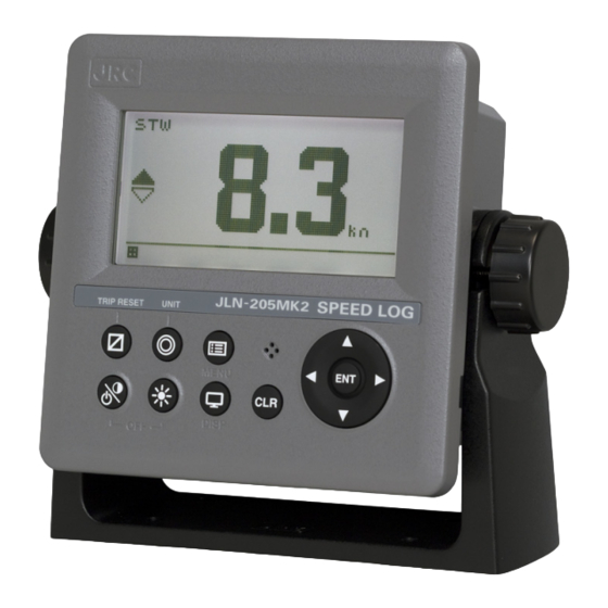
JLN-205MK2
JLN-205MK2
ドップラログ
REFERENCE
REFERENCE
簡易取扱説明書
簡易取扱説明書
QUICK
QUICK
Table of
Contents
Previous
Page
Next
Page
1
2
3
4
5
Advertisement
Chapters
English
8
日本語
118
Table of Contents
Need help?
Do you have a question about the JLR-7900 and is the answer not in the manual?
Ask a question
Questions and answers
Related Manuals for JRC JLR-7900
Marine Equipment JRC JLN-205MK2 Quick Reference
Multi information display (178 pages)
Monitor JRC NWZ-4610 Instruction Manual
Multi information display (120 pages)
Marine Equipment JRC JLN-628 Brochure
Doppler current meter 15''color lcd display version (2 pages)
Marine Equipment JRC JLR-7600 Quick Reference
Multi information display, doppler log, gps navigator (218 pages)
Marine Equipment JRC JFE-680 Instruction Manual
(87 pages)
Marine Equipment JRC JHS-770S Instruction Manual
Marine vhf radiotelephone (158 pages)
Marine Equipment JRC JUE-250 Brochure
Fleetbroadband upgrade path from jrc fleet 33 reliable broadband data and voice dedicated compact solution cost-effective performance and flexibility takes your vessel into future standards (6 pages)
Marine Equipment JRC JUE-95SA Instruction Manual
Inmarsat mini-c, mobile earth station, ship security alert system (70 pages)
Marine Equipment JRC JHS-180 Instruction Manual
Automatic identification system (72 pages)
Marine Equipment JRC JFC-7050 Operation Manual
Echo sounder/fish finder (49 pages)
Marine Equipment JRC JFE-582 Service Manual
(95 pages)
Marine Equipment JRC ECDIS Instruction Manual
(371 pages)
Marine Equipment JRC JAN-7202 Instruction Manual
Bridge alert management system (132 pages)
Marine Equipment JRC JMR-5400 Series Instruction Manual
Multi function display (126 pages)
Marine Equipment JRC JMA-9900 Series Service Manual
Marine radar equipment (125 pages)
Marine Equipment JRC JFE-400 Instruction Manual
(104 pages)
This manual is also suitable for:
Jln-205mk2
Nwz-4610
Jlr-7600
Table of Contents
Print
Rename the bookmark
Delete bookmark?
Delete from my manuals?
Login
Sign In
OR
Sign in with Facebook
Sign in with Google
Upload manual
Upload from disk
Upload from URL


Need help?
Do you have a question about the JLR-7900 and is the answer not in the manual?
Questions and answers