
Related Manuals for JRC JLN-205MK2


Summary of Contents for JRC JLN-205MK2
- Page 1 NWZ-4610/JLN-205MK2 NWZ-4610/JLN-205MK2 MULTI INFORMATION DISPLAY MULTI INFORMATION DISPLAY DOPPLER LO DOPPLER LOG /ドップラログ ドップラログ QUICK QUICK REFERENCE REFERENCE 簡易取扱説明書 簡易取扱説明書...
- Page 3 The MID is the display unit that receives NMEA data items from various sensors to display them. Doppler LOG The JLN-205MK2 provides accurate displays of ship’s speed over a wide range from dead slow to maximum. ● Before attempting to operate this equipment, read this instruction manual thoroughly to ensure correct and safe operation in accordance with the warning instructions and operation procedures.
-
Page 4: Before You Begin
Before You Begin Symbols Used In This Manual In this manual, and on the equipment, we use several warning signs to call your attention to important items that, if not handled correctly, could present danger to yourself or property. These warning note classifications are as described below. Please be fully aware of the importance of these items before using this manual. -
Page 5: Usage Hints
In the event that you spill or drop any liquids or metals etc., turn off the unit, turn off the power supply breaker, and contact your sales agent outlet or one of JRC branch offices, sales centers or liaison offices. Otherwise continuing operation may cause a fire, an electric shock or a malfunction. - Page 6 CAUTION Without qualified service personnel, do not attempt to install this unit. Contact our service center or agent for any electrical work or installation of this unit. Otherwise it may cause a malfunction. Do not install this unit at the place exposed to direct sunlight for a long time or hit by hot wind or where the temperature rises above 55℃.
-
Page 7: External View
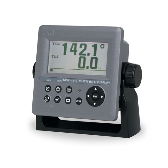
External View ● MID NWZ-4610 Display unit ● Doppler Log JLN-205MK2 Display unit... -
Page 8: Table Of Contents
Contents General Information ....................ⅰ Before You Begin ....................ⅱ Usage Hints ....................ⅲ External View ....................ⅴ Section 1 Introduction ..............1-1 1.1 Function ..............1-1 1.2 Feature ..............1-1 1.3 Components ..............1-2 1.3.1 Standard equipments ..............1-2 1.3.2 Options .............. - Page 9 Section 5 Maintenance ..............5-1 5.1 Daily Maintenance ..............5-2 5.2 Alarm ..............5-3 5.3 Troubleshooting for Malfunction or Abnormalities ......5-4 5.3.1 Troubleshooting ..............5-4 5.3.2 Repair Unit ..............5-5 5.3.3 Regular Replacement Parts ......... 5-5 Section 6 Installation .........
-
Page 11: Section 1 Introduction
2) Doppler Log (JLN-205MK2) The JRC Model JLN-205MK2 Doppler Log is an equipment for measuring accurately the true speed and run of a ship, utilizing the Doppler shift of ultrasonic signals, which are radiated from a trnsducer into sea water downward obliquely to the bow and stern sides, then scattered and reflected in the sea water. -
Page 12: Components
1.3 Components 1.3.1 Standard equipments 1) MID Description Model No. CODE Remarks DISPLAY NWZ-4610 NWZ-4610 Main Body DATA POWER 14 cores 2 m/ With Fuse holder CFQ-5766A CFQ5766A CABLE data, power, contact FUSE MF60NR 250V 1 5ZFGD00205 Display unit 1A fuse FRONT PANEL MTV305018A MTV305018A... -
Page 13: Options
1.3.2 Options 1) MID/Doppler Log Description Model No. CODE Remarks DATA POWER CFQ-5766D CFQ5766D 14 cores 10 m/ With Fuse holder CABLE data, power, contact CFQ-5766F CFQ5766F 14 cores 20 m/ With Fuse holder data, power, contact DATA CABLE CFQ-5767 CFQ5767 4 cores/3 m data 6-pin connector data line only... -
Page 14: Construction
1.4 Construction Display NWZ-4610 (MID/Common) Unit: mm Mass: Approximately 0.8kg... - Page 15 Signal Distributor NQA-4288A (Doppler Log) Unit: mm Mass: 6kg Signal Processor NJC-25 (Doppler Log) Unit: mm Mass: 6kg Transducer NKF-547 (Doppler Log) Unit: mm Mass: 17kg...
-
Page 16: System Configuration
1.5 System Configuration 1) MID T-shaped connector AA-040404-MMM-TL RS-485 RS-485 CFQ-5769 3m CFQ-5769 3m RS-485 External device Daisy chain CFQ-5767 Sensors CFQ-5769 CFQ-5768 3m SENSOR/DATA2 DATA1 SENSOR/DATA2 DATA1 NWZ-4610 NWZ-4610 DC12/24V DATA DC12/24V DATA CFQ-5766A External device * 250V-TTYCS-1 3 ports Sensors Junction Dimmer unit... - Page 17 2) Doppler Log 1 - 7...
-
Page 19: Section 2 Names And Functions Of The Components
Section2 Names and Functions of the Components 2.1 NWZ-4610 Display Unit ●Main Unit(front) Display Operation panel Buzzer Keys Name Functions Power/ Turns on the power. This key also adjusts the Contrast key screen contrast. The power is turned off when the key and this key are pressed at the same time. - Page 20 Reading the Display <Numeric display screen> U: UTC Date and time L: Local time If date and time data is not received, "-" is displayed. Screen title Ship speed and direction Display area Status bar Screen number Freeze indicator The display mode and the screen number During operation, the black part moves.
- Page 21 <Graphic screen> Graph screen (MID) Graph title Current measured value Vertical axis measured value Horizontal axis: Elapsed time [minute] More left data is older. Current measured value Wind direction/wind velocity screen (MID) The left and right keys can be used to switch between true and relative. True wind direction True wind...
- Page 22 <Special screen> Depth for JFE-380/680 (MID) 1) Single Transducer Display mode Position of Transducer Offset Depth Range 2) Dual Transducer Position of Transducer1 Position of Transducer2 Depth of Depth of Transducer1 Transducer2 Offset of Offset of Transducer1 Transducer2 Display mode Range Speed through the water (Doppler Log) STW: Speed through the water...
-
Page 23: Section 3 Display Screen
Section 3 Display Screen 3.1 Display screen The screen is switched each time the key is pressed. Up to six screens can be displayed. The screen after the power is turned on becomes the screen when it is turned off. When the key is pressed, the mode is switched in MID. - Page 24 2) Doppler Log Split screen display The screen can be split into 1 to 4 areas to display multiple information items. 1-split screen 2-split screen 3-split screen 4-split screen...
- Page 25 Enlarged part display Integer part or fraction can be highlighted. Enlarged part screen Enlarged fraction screen...
-
Page 27: Section 4 Operation
Section4 Operation WARNING Do not place a vessel containing water, etc. or a metallic object on this unit. When water spills or when water or the object enters the unit, a fire, an electric shock, or a failure may occur. Do not use this unit at a voltage other than the supply voltage stated on the unit. -
Page 28: Basic Operation
4.1 Basic Operation 4.1.1 Turning on the power When the main power is turned on, the power to the display unit is automatically turned on. In the state in which the power is turned off by the display unit key operation, pressing the key turns on the power. -
Page 29: Starting (Normal)
If the self-diagnosis results are errors “NG,” the results are displayed as follows. Caution When any abnormality (NG) is found, contact JRC or one of our agents. 4.1.4 Starting (Abnormal) When the program is corrupted, the following screen is displayed. Turn off the power and contact JRC or one of our agents. -
Page 30: Turning Off The Power
4.1.5 Turning off the power If the key and the key are pressed and held down simultaneously, the power will be turned off and the screen display will turn off. Supplement The power may be turned on due to the release timing of your finger. In this case, first release the and then release the 4.1.6 Adjusting the back light (lighting) by using the key... -
Page 31: Turning Off The Alarm Buzzer
4.1.8 Turning off the alarm buzzer Buzzer sound can be turned off by pressing The buzzer sounds if an alarm occurs. 4.1.9 Alarm display When an alarm occurs, the event is notified with a popup menu and alarm sound. When is pressed, the popup menu is cleared and the buzzer sound stops. - Page 32 4.1.11 Switchimg display (automatic) Display can be switched automaticaly. 1. Select "AUTO SCREEN" and set to "ON" in each display setting. 2. Select switching time from 1 to 10 seconds. 3. Press and hold the key for 3seconds to start the autoscreen function. The display switches to next screen...
-
Page 33: User Mode Change (Mid)
4.1.12 User mode change (MID) The user mode can be changed. Up to three user modes are available, and six screens can be registered in one mode. Press the key. Each time the key is pressed, mode 1 changes to mode 2 and to mode 3. Display4 Display3 Display5... -
Page 34: User Setting Screen Display (Mid)
4.1.13 User setting screen display (MID) From among the screens registered in the display screen, the user-set screen can be displayed. The user-set screen can also be displayed quickly from other screen by registering the most often-used screen. The user-set screen cannot be registered in each use mode. Press the key. -
Page 35: Resetting A Trip (Log)
4.1.14 Resetting a TRIP (LOG) A trip value can be reset. A total travel distance cannot be reset. Press for 1 second. The TRIP screen is reset to 0.00NM. 4.1.15 Changing a unit of the vessel speed (LOG) The unit of the vessel speed can be switched between kn and m/s. Press Whenever the key is pressed, the setting switches between kn and m/s. -
Page 36: Menu Operation
4.2 Menu Operation 4.2.1 Selecting items from the menus This section shows the procedure for selecting items from the menus and determining the selection. Procedure 1. Move the cursor to a required item by using and press The item is selected and a submenu is opened to enable selection of details. The selected item is displayed in reverse video. -
Page 37: Entering A Numeric Value
4.2.2 Entering a numeric value This section describes the procedure for entering a numeric value. Procedure 1. Move the cursor to the field in which a value is to be entered by using 2. Set a numeric value to be entered by using and press 3.... -
Page 38: Changing To A Maintenance Mode
4.2.3 Changing to a maintenance mode Before starting installation, the mode must be changed to a maintenance mode to prevent an operation error. Change the mode to a maintenance mode by the initial operation. Procedure 1. Display a main menu by pressing (normal mode). -
Page 39: Setting A Model
4.2.4 Setting a model The model is set. When the model is set, the setting contents are initialized. Procedure Refer to “4.2.3 Changing to a maintenance mode” to display the maintenance menu. Select “DISPLAY TYPE” by using and press Select “MID” or "LOG" by using and press When the following popup menu is displayed, press “YES”. -
Page 40: Menu List
4.2.5 Menu List 1) MID 【】Choice Main menu Sub-menu1 Explanation Default Sub-menu2 Sub-menu3 1> DISPLAY Adjust the LCD contrast. CONTRAST 【 1(dark)~13(light) 】 Adjust the LCD dimmer. DIMMER MAXIMUM Brightness can be changed by using [DIM] key. DIMMER TYPCAL ・Enter the hihest value in "MAXIMUM" and lowest value in "MINIMUM". - Page 41 Main menu Sub-menu1 Explanation Default Sub-menu2 Sub-menu3 2> SYSTEM UNIT Selecting the units. The unit of Distance/Speed DIST/SPD 【 NM,kn、km,km/h、mi,mi/h、m,m/s 】 TEMP The unit of Water temperature 【 ℃,°F 】 ℃ DEPTH The unit of Depth 【 m,ft,fm 】 WIND The unit of Wind 【...
- Page 42 Main menu Sub-menu1 Explanation Default Sub-menu2 Sub-menu3 An alarm occurs when the water depth matches the DEPTH set parameters. 【Over, Under, In range, Out range, OFF】 WIND An alarm occurs when the wind velocity matches the set parameters. 【 Over, OFF 】 AIR TEMP An alarm occurs when the air temperature matches the set parameters.
- Page 43 Main menu Sub-menu1 Explanation Default Sub-menu2 Sub-menu3 CONTACT OUTPUT Selectting a contact input port. 【 200pluse/NM, 400pluse/NM, OFF 】 DIAGNOSIS Outputting alarm histry and setting vlaue. ・Data is output from a data IN/OUT1 port. 7> MAINTENANCE Data that is received from the serial port can be INPUT DATA displayed on a screen.
- Page 44 Main menu Sub-menu1 Explanation Default Sub-menu2 Sub-menu3 DEMO MODE To start demonstration, set to "START". To end demonstration, set to "END". ・ During execution of demonstration, [S] is displayed in blinking mode at the bottom of the screen. 10> SOFT UPDATE DISPLAY Display program update.
- Page 45 2) Doppler Log 【】Choice Main menu Sub-menu1 Explanation Default Sub-menu2 Sub-menu3 1> DISPLAY Adjust the LCD contrast. CONTRAST 【 1(dark)~13(light) 】 Adjust the LCD dimmer. DIMMR MAXIMUM Brightness can be changed by using [DIM] key. DIMMER TYPCAL ・Enter the hihest value in "MAXIMUM" and lowest value in "MINIMUM".
- Page 46 Main menu Sub-menu1 Explanation Default Sub-menu2 Sub-menu3 The alarm function when an alarm occurs can be set. 4> ALARM ・Alarm sound setting ・LCD color switching (White or Orange). SYSTEM An alarm occurs when the system failure occurs. 【ON, OFF】 An alarm occurs when the ship speed matches the SPEED set parameters.
- Page 47 Main menu Sub-menu1 Explanation Default Sub-menu2 Sub-menu3 6> INTERFACE DATA I/O Select the output format. DATA IN/OUT 1,2,3 NMEA 【 NMEA, IEC 】 IO1: Select the port to "SEND" or "RECEIVE". SEND Cannot set DATA IN/OUT1, 2, 3. ・When the port is set for output, output sentence and IO2: output interval can be selected.
- Page 48 Main menu Sub-menu1 Explanation Default Sub-menu2 Sub-menu3 7> MAINTENANCE Data that is received from the serial port can be INPUT DATA displayed on a screen. ・Display format(ASCII/BINARY) can be selected. DIAGNOSIS Self-diagnosis of ROM, RAM, and serial port can be DISPLAY DIAG performed Self-diagnosis of LCD can be performed.
- Page 49 Main menu Sub-menu1 Explanation Default Sub-menu2 Sub-menu3 11> MAIN/SUB Selects a type 【MAIN, SUB】 MAIN 12> DISPLAY TYPE Setting a model. ・When the model is set, the setting contents are initialized. To identify a display unit on the RS-485 network, set 13>...
-
Page 50: Display Category And Contents
4.2.6 Display category and contents 1) MID Category Display contents Segmentation1 Segmentation2 Segmentatuon3 Segmentation4 OWN SHIP PITCH ROLL HEAVING LAT/LON WEATHER WATER TEMP AIR TEMP PRESSURE HUMIDITY DOPPLER BOW STW STERN STW SOG(LOG) BOW SOG(LOG) STERN SOG(LOG) CURRENT L1 SPD CURRENT L1 DIR CURRENT L2 SPD CURRENT L2 DIR... - Page 51 2) Doppler Log Category Display contents Segmentation1 Segmentation2 Segmentatuon3 Segmentation4 DOPPLER TRIP SPECIAL STW1 STW2 STW3 GRAPHIC 4-25...
- Page 52 4-26...
-
Page 53: Section 5 Maintenance
JRC branch offices, sales centers or liaison offices. Never attempt to check or repair the unit. Continuing operation may cause a fire or an electric shock. -
Page 54: Daily Maintenance
5.1 Daily Maintenance WARNING Do not remove the cover of this unit. Otherwise, you may touch a high-voltage part and suffer from an electric shock. Turn off the power on/off switch, and turn off the power supply breaker when you check this unit for maintenance.」 「an electric shock. -
Page 55: Alarm
5.2 Alarm Check the alarm details referring to the list shown below. Alarm List 1) Common Message Message Contents Alarm Causes Number ROM[1] Flash ROM Deletion, Write Error (ROM[1]) ROM[2] Flash ROM Deletion, Write Error (ROM[2]) ROM[3] SEEPROM Deletion, Write Error RAM Read, Write Error SIO[0] Serial Port Error (SIO[0]) -
Page 56: Troubleshooting For Malfunction Or Abnormalities
In the event that smoking or burning odors are detected, immediately terminate operation of the unit and contact your sales agent outlet or one of JRC branch offices, sales centers or liaison offices. Never attempt to check or repair the unit. -
Page 57: Repair Unit
Notes FRONT PANEL FRONT PANEL MPBC47673 PRODUCT NAMEPLATE 5.3.3 Regular Replacement Parts Parts which should be regularly replaced are shown below. Contact JRC or an affiliate to order. Name Model Life Notes Approximately 5 years of LCD UNIT CCN-423 40000 hours... -
Page 59: Section 6 Installation
Section 6 Installation CAUTION Consult with JRC or our agents to install. Installation by unauthorized personnel may result in a malfunction. Do not install this unit at the place exposed to direct sunlight for a long time or hit by hot wind or where the temperature rises above 55℃. Otherwise it may cause a fire or a breakdown. -
Page 60: Affixing Display Unit Nameplate Labels
6.1 Affixing Display Unit Nameplate Labels Peel the label of the equipment to be used from the accessory product nameplate, and affix it to the center of the front panel. Product Nameplate (Accessory) Display Unit Front Peel the label of the equipment to be used from the accessory model identification plate, and affix it over the upper left blank part of the unit nameplate at the center of the rear case. -
Page 61: Display Unit Installation
6.2 Display Unit Installation 6.2.1 Selecting the position for installation WARNING Install this unit at least 1 m away from any magnetic compasses. Installation near a magnetic compass may interfere with the magnetic compass, resulting in an accident. Do not use this unit at the voltage other than its rated voltage. Otherwise it may result in a fire, an electric shock or a failure. -
Page 62: Mounting The Display Unit Using A Rack
6.2.2 Mounting the display unit using a rack Use the following procedure. 1) Fix the desktop rack at the required installation position by using the mounting screws (φ4~6 screw or wood screw, L>=15mm, provided by the shipyard). 2) Insert the front panel into the main unit. 3) Attach the rotational washer on the side of the main unit. - Page 63 285 or more 190 or more Required installation space (Unit: mm) Mount (bottom)
-
Page 64: Mounting Using A Flush Mount
6.2.3 Mounting using a flush mount Use the following procedure. See the diagram below for the mounting space and mounting holes. Do not tighten a screw too much. Doing so may result in damage of installation holes. Insert the main unit in the installation location. Fix the main unit using the mounting screws (φ4 screw or wood screw, L>=10mm, provided by the shipyard). - Page 65 Provide maintenance space or more (Square hole) Mounting hole ※About the corner C11, (Screw pitch) may want to cut φ25...
-
Page 66: Removing The Display Unit By Flush Mounting
6.2.4 Removing the display unit by flush mounting Use the following procedure to remove the display unit. Insert a hexagonal wrench into the holes (2) at the bottom of the front panel. Remove the front panel by pressing down the hexagonal wrench. Mounting wall Front panel Press down... -
Page 67: Doppler Log Installation
6.3 Doppler Log Installation To install the Doppler Log, refer to "SERVICE MANUAL" of the Doppler Log JLN-205MK2. 6.4 Cable Connection Unit (Rear Connector) [DATA 1] [SENSOR/DATA 2] Share data between display units Daisy-chain [TERM.] Or, connect with external device. -
Page 68: Dc12/24V Data Connector (Mid/Log)
Input and output to the specifications set by “DATA green Transmission IN/OUT3.” Brown (DATA I/O 3) SD6-B Black Chassis Chassis earth (Shield) Earth To connect the Doppler Log, refer to "SERVIC MANUAL" or "INSTALLATION MANUAL" of the Doppler Log (JLN-205MK2). 6-10... - Page 69 [Input/Output Condition for Serial Transmission] The data power cable (CFQ-5766) has three serial transmission channels. The input/output settings for DATA I/O "1" and "2" are linked to each other. As listed below, four connections and settings can be made. For the input/output settings for channels, see "4.9.5 Setting a serial port". Data Power Cable CFQ-5766A: 2 m (Accessory)
- Page 70 [Input/Output Circuit] NWZ-4610 Display Unit [Contact Output] Relay 3: Orange 4: Yellow 5: Green Contact maximum 30 VDC/1.0 A [Contact Input/Analog Input] NCM-227 Dimmer Unit 6: Blue 7: Purple or Contact Connection [Serial Transmission] IEC61162-1 (NMEA) Output Setting SD-A Input SD-B IEC61162-1 (NMEA) Input Setting...
-
Page 71: Data1 Connector (Mid/Log)
6.4.2 DATA1 connector (MID/LOG) TERM. Switch Display Unit Rear: Connector Pin Number Display Unit Rear CFQ5769 Data Cable CFQ-5769: 3 m (Option) Terminal Name Explanation Number (CFQ-5769) Brown SD1-A Serial Connect to the display unit for serial transmission Transmission SD1-B (RS-485) Green SD1-C... - Page 72 [T-SHAPED CONNECTOR] This T-SHAPED CONNECTOR can be used to extend cables and connect multiple units (up to 10 units). CFQ-5769 CFQ-5769 T-SHAPED CONNECTOR (option) Type name: AA-040404-MMM-TL Code: 5JCDX00071 CFQ-5769 [To Extend the Cable] CFQ-5769: 3 m x necessary number of cables T-SHAPED CONNECTOR Same number as CFQ-5769 CFQ-5769: 3 m...
- Page 73 [To Connect Multiple Units] Up to 10 units can be connected. The number of cables and the number of T-SHAPED CONNECTOR vary depending on the distance between display units. CFQ-5769: 3 m CFQ-5769: 3 m CFQ5768 CFQ5768 ... 3 . 4 . 5 . 6 . 7 . 8 . Term.: ON (up) Term.: OFF (down) Term.: ON (up)
- Page 74 [To Group Dimmer Control] The following shows an example of grouping 10 units (maximum number of connections) into 3 units, 3 units, and 4 units. CFQ-5769: 3 m RS485ID:01 RS485ID:02 RS485ID:03 12.3 12.3 12.3 Dimmer group: 01 Key operation Dimmer: Key RS485ID:06 RS485ID:05 RS485ID:04...
-
Page 75: Sensor/Data2 Connector (Mid)
6.4.3 SENSOR/DATA2 connector (MID) [For serial communication with external device] Display Unit Rear: Connector Pin Number Display Unit Rear CFQ5767 Data cable CFQ-5767: 3 m (option) Terminal Name Explanation Number Unused White Serial RXD2-B Input to the specification set by “DATA IN/OUT4.” transmission Green RXD2-A... - Page 76 [For outputting together four data from one port] Terminal Name Example Number (CFQ-5767) White Serial RXD2-A transmission Input Position Green RXD2-B (DATA IN 4) CFQ5767 Yellow TXD2-A Position/ Serial water depth Brown TXD2-B transmission Output Water (DATA OUT 4) temperature/ current Output together from this port Display Unit Rear...
- Page 77 [To daisy-chain the units] Display Unit Rear: Connector Pin Number ① ⑤ ⑥ ② ④ ③ Display Unit Rear CFQ5768 Data cable CFQ-5768: 3 m (option) Terminal Name Example Number (CFQ-5768) Power supply DCOUT+ Supplies the power to the subsequent display unit. output Black DCOUT-...
- Page 78 Up to three units can be daisy-chained. To make this connection, set the daisy-chain setting to ON. Display Unit Data power cable CFQ: 5768: 3 m (option) Data power cable CFQ-5768: 3 m (option) 6 pins Power supply CFQ5766 Data power cable CFQ-5766A: 2 m (accessory)
-
Page 79: Optional Peripheral Connection
6.5 Optional Peripheral Connection 6.5.1 Dimmer unit connection The brightness of the backlight can be changed at a location away from the display unit by connecting the dimmer unit (NCM-227). DATA1 NWZ-4610 Display Unit SENSOR /DATA2 DC12/24V DATA CFQ-5766A Data Power Cable (2 m) CQD-10 Junction Box... - Page 80 6-22...
-
Page 81: Section 7 After Service
Section7 After Service 7.1 Warranty ● Specific periods may vary based on our warranty policies, but the standard warranty period is one year from the date of purchase. 7.2 Repair parts stocking Period ● We keeps functional repair parts for this equipment (parts necessary for the functioning of this equipment) in stock for 10 years from the discontinuation of production. -
Page 83: Section 8 Disposal
Section 8 Disposal 8.1 Disposal of the Equipment Observe all local laws and regulations when disposing of those units. The battery is not used for those units. -
Page 85: Display Unit
Section9 Specifications 9.1 Display Unit 1) Basic Display Unit: 4.5 inch monochrome LCD 128 64 dots Backlight: White LED or orange LED (selectable) Dimmer Levels: 4 levels (Bright, Medium, Dark, OFF) Dimmer control: Key or external dimmer unit ... - Page 86 3) Interface 3-1) MID (1) Serial Transmission Channel Specification Notes DATA IN/OUT1 RS-422 Input or Output NMAE, IEC DATA IN/OUT2 RS-422 Input or Output NMEA, IEC DATA IN/OUT3 RS-422 Input or Output NMEA, IEC DATA IN/OUT4 RS-422 Input or Output NMEA, IEC Daisy chain RS-485...
-
Page 87: Doppler Log
9.2 Doppler Log 1) Basic Operation system : Dual - beam pulse Doppler system Operation frequency : 2MHz Speed measurement range : –10.0 to +40.0 kn Run distance display range : 0 to 99999.99nm (However, NWW-7 of the option is 0 to 9999.99nm ) ... - Page 89 有毒有害物质或元素的名称及含量 (Names & Content of toxic and hazardous substances or elements) 形式名 : NWZ-4610 名称 : Display unit (Type) (Name) 有毒有害物质或元素 (Toxic and Hazardous Substances and Elements) 部件名称 (Part name) 铅 汞 镉 六价铬 多溴联苯 多溴二苯醚 (Pb) (Hg) (Cd) (PBB) (PBDE) ×...
- Page 91 NWZ-4610/JLN-205MK2 NWZ-4610/JLN-205MK2 MULTI INFORMATION DISPLAY MULTI INFORMATION DISPLAY ドップラログ ドップラログ 簡易取扱説明書 簡易取扱説明書...
- Page 93 はじめに このたびは、当社の NWZ-4610 をお買い上げいただきまして、誠にありがとうございます。本装 置は、マルチインフォメーションディスプレイ(Multi Information Display (MID))、ドップラログ (JLN-205MK2)、の表示器として利用することができます。 種々のセンサーから NMEA データを受信し、表示する装置です。 ドップラログ 低速から高速まで幅広く船の速度を計測し表示する装置です。 ● お使いになる前に、この取扱説明書をよくお読みのうえ、正しくお使いください。 ● 取扱説明書は必要なときに参照できるように大切に保管ください。 万一、ご使用中にわからないことや不具合が生じたときにお役立てください。...
- Page 94 ご使用のまえに 本書に使用している絵表示 この取扱説明書および製品への表示では、製品を安全に正しくお使いいただき、あなたや 他の人々への危害や財産への損害を未然に防止するために、いろいろな絵表示をしていま す。その表示と意味は次のようになっています。 内容をよく理解してから本文をお読みください。 警告 この表示を無視して、誤った取り扱いをすると、人が死亡、 または重傷を負う可能性が想定される内容を示しています。 この表示を無視して、誤った取り扱いをすると、人が傷害を 注意 負う可能性が想定される内容、および物的損害のみの発生が 想定される内容を示しています。 この取扱説明書および装置に使用している絵表示の例 △記号は注意(危険・警告を含む)を促す内容があることを告げ るものです。 図の中に具体的な注意内容(左図の場合は感電注意) が描かれています。 記号は禁止の行為であることを告げるものです。 図の中や近傍に具体的な禁止内容(左図の場合は分解禁止)が描か れています 記号は行為を強制したり指示する内容を告げるものです。 図に中に具体的な指示内容(左図の場合は電源プラグをコンセント から抜け)が描かれています。 警告ラベルについて 本製品の上カバーには警告ラベルが貼ってあります。 警告ラベルを取り外したり、破損したり、改変を絶対にしないで下さい。...
- Page 95 ご使用上の注意 警告 本装置のカバーは絶対にはずさないでください。 内部の高電圧に触れて感電するおそれがあります。 本装置の保守点検を行なう場合は、電源スイッチを切り、電源ブレーカをオフに してください。感電・故障のおそれがあります。 本装置を分解・改造しないでください。火災・感電・故障のおそれがあります。 本装置の上に水などの入った容器または小さな金属物を置かないでください。こ ぼれたり、中に入ったりした場合、火災・感電・故障のおそれがあります。 本装置の定格電圧以外でこのユニットを使用しないでください。火災・感電・故 障のおそれがあります。 濡れた手で電源コードの抜き差をしたり、スイッチ類を操作したりしないでくだ さい。感電のおそれがあります。 電源コードの傷つけ、破損と加工をしないでください。重いものを乗せたり、加 熱したり、引っ張ったり、無理に曲げたりすると電源コードは破損して、火災・ 感電のおそれがあります。 装置内部を点検や修理しないでください。装置内部の点検や修理サービスは、お 買い上げの販売店・代理店または、当社の各支店・営業所・出張所にご依頼くだ さい。火災・感電を引き起こすおそれがあります。 万一、内部に水や金属の異物が入った場合は、まず本装置の電源スイッチを切り、 電源ブレーカをオフにしてください。その後、お買い上げの販売店・代理店また は、当社の各支店・営業所・出張所にご連絡ください。そのまま使用すると火災・ 感電・故障のおそれがあります。 万一、煙が出ている、変な臭いがする、異常に熱いなどの異常に気がついたとき は、直ちに本装置の電源スイッチを切り、電源ブレーカをオフにしてください。 その後、お買い上げの販売店・代理店または、当社の各支店・営業所・出張所に ご連絡ください。そのまま使用すると火災・感電のおそれがあります。...
- Page 96 注意 本装置の電気工事はお買い上げの販売店・代理店または、 当社の各支店・営業所・ 出張所にご依頼ください。 専門整備員以外の電気工事は動作不良になるおそれがあります。 直射日光が長時間装置に当たる場所、熱風が当たる場所、温度が55℃以上にな る所では本装置を使用したり、放置したりしないでください。 火災・故障のおそれがあります。 ぐらついた台の上や傾いた所のような不安定な場所に置かないでください。 落ちたり、倒れたりして、けが・故障のおそれがあります。 本装置を戸棚の中に置いたり、段ボールのような通気性の悪いもので覆ったりし ないでください。 熱がこもって火災・故障のおそれがあります。 本装置を、寒いところから暖かいところへ急に移したとき、窓の内部につゆ(水 滴、結露)が付いて液晶部が見えにくくなることがあります。そのようなときは、 しばらく乾燥のため放置してからお使いください。 据付時にはアース端子に、アース板およびアース線を確実に接続してください。 故障や漏電のときに、感電のおそれがあります。 船が陸に上がっているとき(上架中)はドップラログの電源を入れないでくださ い。 送受波器がこわれるおそれがあります。 機器表面を掃除するときは、シンナーやベンジンなどの有機溶媒は絶対に使用し ないでください。表面の掃除は、チリ、ゴミを取り除き、清潔な布で乾拭きする ようにしてください。 表面の塗装を傷めるおそれがあります。...
- Page 97 装置外観 ● MID NWZ-4610 表示器 ● ドップラログ JLN-205MK2 表示器...
- Page 98 目次 はじめに ..........ⅰ ご使用のまえに ..........ⅱ ご使用上の注意 ..........ⅲ 装置外観 ..........ⅴ 第1章 装置のあらまし ........1-1 1.1 機能 ........1-1 1.2 特長 ........1-1 1.3 構成 ........1-2 1.3.1 標準構成 ........ 1-2 1.3.2 オプション ........ 1-3 1.4 構造 ........1-4 1.5...
- Page 99 第5章 保守・点検 ......... 5-1 5.1 日常の保守 ......... 5-2 5.2 アラーム ......... 5-3 5.3 トラブルシューティング ......5-4 5.3.1 トラブルシューティング ......5-4 5.3.2 補修用ユニット ......5-5 5.3.3 定期交換部品 ......5-5 第6章 装備 ......... 6-1 6.1 銘板シールの貼り付け ......... 6-2 6.1.1 製品銘板の貼り付け ......6-2 6.1.2...
-
Page 101: 第1章 装置のあらまし
す。 2)ドップラログ(JLN-205MK2) ドップラログは、船底に装備された送受波器から海水中の船首方向と船尾方向に超音波信号を 放射し、海水中から反射した超音波信号のドップラー効果を利用して、船の真の速度と航程を正 確に測定する装置です。 この装置は、船底から3m 以内の海水に対する相対速度を測定しています。従って海流などの 速度を含まない主機の出力に応じた船速を得ることができます。パルス方式の送受信を行い船底 近傍の信号は除いていますので、吃水の変化で生じる船速誤差は発生しません。 また、船首船尾の2方向に超音波信号を発射するデュアルビーム方式を採用し、トリム変化に よる船速誤差も大幅に軽減されています。 この装置は、レーダや ECDIS などの他の機器へ計測した情報を提供します。 1.2 特長 各装置には、次のような特長があります。 1) MID ・ 種々の NMEA データ表示 ・ 表示内容と画面レイアウト選択 ・ デイジーチェーンによる電源分配 ・ モード毎の表示画面選択 ・ RS-485 による表示器間でのデータ共有とディマー連動 2) ドップラログ(JLN-205MK2) ・ 対水船速の測定 ・ 動揺による誤差を軽減 ・ 高信頼の小型送受波器... -
Page 102: 構成
1.3 構成 1.3.1 標準構成 1) MID 番号 品名 型名 コード 数量 備考 NWZ-4610 NWZ-4610 表示器 本体 14 芯 2m / データ CFQ-5766A CFQ5766A ヒューズホルダ付 電源ケーブル データ,電源,接点 MF60NR 250V 1 5ZFGD00205 1A ヒューズ ヒューズ MTV305018A MTV305018A フロントパネル 卓上架台 ノブボルト MPBX47065 MPBX47065 卓上架台キット... -
Page 103: オプション
1.3.2 オプション 1) MID/ドップラログ 番号 品名 型名 コード 数量 備考 14 芯 10m / ヒューズホルダ付 CFQ-5766D CFQ5766D データ,電源,接点 データ電源ケーブル 14 芯 20m / ヒューズホルダ付 CFQ-5766F CFQ5766F データ,電源,接点 CFQ-5767 CFQ5767 データケーブル データ入出力追加用 CFQ-5768 CFQ5768 データケーブル デイジーチェーン用 CFQ-5769 CFQ5769 データケーブル RS485 通信用 AA-040404-MMM T 字コネクタ... -
Page 104: 構造
1.4 構造 NWZ-4610 表示器(MID/全機種共通) 単位: mm 質量: 約0.8 kg... - Page 105 データ分配器 NQA-4288A(ドップラログ) 単位: mm 質量: 6kg 信号処理器 NJC-25(ドップラログ) 単位: mm 質量: 6kg 送受波器 NKF-547(ドップラログ) 単位: mm 質量: 17kg...
-
Page 106: 総合系統図
1.5 総合系統図 1) MID T 字コネクタ AA-040404-MMM-TL RS-485 RS-485 CFQ-5769 CFQ-5769 RS-485 CFQ-5769 外部機器 センサー類 CFQ-5767 デイジーチェーン CFQ-5768 SENSOR/DATA2 DATA1 SENSOR/DATA2 DATA1 NWZ-4610 NWZ-4610 DC12/24V DATA DC12/24V DATA CFQ-5766A 外部機器 ※250V-TTYCS-1 センサー類 3 ポート 接続箱 CQD-10 ディマーユニット ※250V-TTYCS-1 NCM-227 Max15m ※250V-TTYCS-1 ログパルス... - Page 107 2)ドップラログ...
-
Page 109: 第2章 各部の名称とはたらき
第2章 各部の名称とはたらき 2.1 NWZ-4610 表示器 ●本体(前面) ディスプレイ ブザー 操作パネル No. 操作パネル 名称 はたらき (機能) 電源/コントラス 電源を入れます。コントラストを調整します トキー キーと同時に押すと電源が切れます 照明キー バックライトの明るさを調整します メニューキー メインメニューを表示します 表示切替キー 表示画面を切り替えます クリアキー 操作のキャンセルをします アラームを停止します カーソルキー カーソルを移動します 入力キー 操作を決定します USER キー(MID) ユーザ登録画面に切り替えます(MID) 航程リセットキー 1 秒長押しで区間航程をリセットします(LOG) (LOG) MODE キー(MID) 利用モードを切り替えます(MID) 単位切替キー... - Page 110 ●ディスプレイの見方 【数値表示画面】 U:UTC 日時 L:ローカル時刻 日時データを受信していない場合は「-」表示 画面タイトル 表示エリア 船速向き ステータスバー 画面番号 フリーズインジケータ 表示しているモードと画面の番号を表示 作動中は黒部分が動きます。 します。 黒部分が動かない場合は画面が を押すと D1~D6:画面番号を 作動していません。 3 秒間表示します。 を押すと M1~M3:モードを アラームアイコン 3 秒間表示します。 アラームが発生している間、表示します。 モード M1~M3 表示は MID のみの機能です。 アラーム内容は、アラーム履歴をご確認く [S]:シミュレーションモード ださい シミュレーションモード中は[S]が 点滅します。 [M]:装備モード 装備モード中は[M]が点灯します。 シミュレーションモード中は点灯し ・COG(進路)画面(MID) ません。...
- Page 111 【グラフフィック画面、グラフ画面】 ・グラフ画面(MID) グラフタイトル 現在の測定値 縦軸 測定値 横軸:経過時間[分] 現在の測定値 ・風向風速画面(MID) 左右キーで真/相対を切り替えることができます。 真風向 風向 真風速 風上からの矢印...
- Page 112 【特殊画面】 ・水深表示(JFE-380/680 専用)画面(MID) 1) 1 振動子 表示モード 振動子位置 オフセット レンジ 水深 2) 2 振動子 振動子 1 位置 振動子 2 位置 振動子 2 振動子 1 水深 水深 振動子 1 振動子 2 オフセット オフセット 表示モード レンジ ・対水船速画面(ドップラログ) 対水船速 船速向き 区間航程 総距離 全航程距離を表示します。リセットは を長押しするとリセットされます...
-
Page 113: 第3章 表示画面
第3章 表示画面 3.1 表示画面 を押すごとに画面(D1,D2,D3,D4,D5,D6)が切り替わります。表示できるのは最大 6 画面です。 電源投入後の画面は、電源断したときの画面となります。 また、MID は を押すとモード(M1,M2,M3)が切り替わります。 下記の画面が、工場出荷時に設定されています。 1) MID... - Page 114 2)ドップラログ 【分割画面表示】 画面を 1~4 分割して複数の情報を表示することができます。 1 分割画面 2 分割画面 3 分割画面 4 分割画面...
- Page 115 【部分拡大表示】 整数部または小数部を強調して表示することができます。 整数部拡大画面 小数部拡大画面...
-
Page 117: 第4章 操作方法
第4章 操作方法 警告 本装置の上に水などの入った容器または小さな金属物を置かないでくださ い。こぼれたり、中に入ったりした場合、火災・感電・故障のおそれがあ ります。 本装置の定格電圧以外でこのユニットを使用しないでください。 火災・感電・故障のおそれがあります。 濡れた手で電源コードの抜き差ししたり、スイッチ類の操作をしたりしな いでください。感電のおそれがあります。 電源コードの傷つけ、破損、加工をしないでください。 重いものを乗せたり、加熱したり、引っ張ったり、無理に曲げたりすると 電源コードは破損して、火災・感電のおそれがあります。 注意 本装置を、寒いところから暖かいところへ急に移したとき、窓の内部につゆ (水滴、結露)が付いて液晶部が見えにくくなることがあります。そのよう なときは、しばらく乾燥のため放置してからお使いください。 船が陸に上がっているとき(上架中)はドップラログの電源を入れないでく ださい。 送受波器がこわれるおそれがあります。... -
Page 118: 基本操作
4.1 基本操作 4.1.1 電源の投入 配電盤の主電源を入れると表示器電源は自動的に投入されます。 表示器のキー操作で電源断している状態では、 を押すと電源が投入されます。 主電源 ON 主電源 OFF 状態 電源キーON オープニング画面 主電源 ON 状態 初回電源 ON 時 機種選択画面が表示されますので、 で機種を選択し を押してください。 機種 間違えて LOG を選択した場合 「4.2.4 機種設定を行う」の「注意」を参照してください。 注 意 電源が入らない場合には、配電盤の主電源や本装置へのケーブル接続をご確認ください。... -
Page 119: 起動(正常
4.1.2 起動(正常) 自己診断の結果が全て'OK'であった時、自動的に通常画面に切り替わります。 全て OK ・ドップラログの電源投入時 主電源で電源投入した場合は、安全のため振動子保護機能が働き、画面に下記が表示されます。 「4.1.5 電源の切断」の操作で電源を切断し、電源キー操作で再度電源を投入してください。 Please turn on the power again. デンゲンヲイレナオシテクダサイ または 注意 振動子保護機能とは 空中で振動子を作動させると、振動子故障の原因になるため、その保護機能です。 振動子が水中にあることを確かめてから電源を投入してください。 4.1.3 起動(異常) 自己診断結果に異常(NG)がある場合は、下記のように結果を表示します。 注 意 異常(NG)があるときには、当社または代理店にご連絡ください。 4.1.4 起動(異常) プログラムが破損している場合は、下図の画面が表示されます。電源を切断し、当社または代理 店へご連絡ください。 R0004 Recovery mode. -
Page 120: 電源の切断
電源の切断 4.1.5 と を押し、同時にキーを離すと電源が断となり画面が消えます。 補 足 指を離すタイミングによっては、再度電源が入ってしまうことがあります。 その場合 の後に を離すように操作してください。 バックライトの調節 4.1.6 ディスプレイと操作パネルのバックライトの明るさを4段階(明、中、暗、断)に調節することがで きます。 を押すたびに、明→中→暗→断→暗→中→明・・・と切り替わります。 補 足 ・オフ以外は各明るさのレベル設定ができます。 ・バックライトは、ディマーユニットでも調整できます。 ・バックライトの明るさに連動してキーパネルの明るさも変わります。 コントラストの調節 4.1.7 コントラストを13段階で調節することができます。 を押すごとに、 現在設定から薄く(または濃く)なっていき、 最も薄く(または濃く)なったら除々 に濃く(または薄く)なります。... -
Page 121: アラームブザーの停止
アラームブザーの停止 4.1.8 ブザーが鳴っているとき、 を押すとブザー音を停止することができます ブザー音はアラームが発生した場合に鳴ります。 アラームの表示 4.1.9 アラームが発生すると、ポップアップとブザー音でアラーム発生を知らせます。 を押すと、ポップアップとブザー音は停止しますが、アラームが解除されるまではステー タスバーに「 」を表示します。 ポップアップとブザー音が停止した後も、アラームが解除されるまでは無効な数値が点滅します。 画面を切り替える 4.1.10 を押すごとに表示画面が切り替わります。 画面 4 画面 3 (D4) 画面 5 (D3) (D5) 画面 2 画面 6 (D2) (D6) 画面 1 (D1) -
Page 122: 画面を切り替える(自動
画面を切り替える(自動) 4.1.11 キー操作をせずに各画面が切り替わります。 1. 各画面において、オートスクリーンをオンに設定します。 2. キリカエジカン(1~10 秒)を設定します。 3. を押すと、オートスクリーンを開始します。 設定した時間で 次画面に切り替わります 画面 4 画面 3 (D4) 画面 5 (D3) (D5) 画面 2 画面 6 (D2) (D6) 画面 1 (D1) -
Page 123: 利用モードを切り替える (Mid)
利用モードを切り替える (MID) 4.1.12 利用モードは、3 モードまであり、1 モードに 6 画面を登録することができます。 を押します。 押す度に、モード 1→モード 2→モード 3 が切り替わります。 画面 4 画面 3 画面 5 (M3D4) (M3D3) (M3D5) 画面 2 画面 6 (M3D2) (M3D6) 画面 1 (M3D1) 画面 4 画面 3 画面 5 (M2D4) (M2D3) (M2D5) 画面... -
Page 124: ユーザ画面に切り替える (Mid)
ユーザ画面に切り替える (MID) 4.1.13 表示画面に登録された画面の中から、ユーザが設定した画面を表示することができます。 最も利用する画面を登録することで、他の画面からでもすぐに表示することができます。 利用モードごとに登録することはできません。 を押します。 元の画面に戻すには、 を押します。 例)画面4をユーザ設定した場合 画面 4 画面 3 (D4) 画面 5 (D3) (D5) 画面 2 画面 6 (D2) (D6) 画面 1 (D1) -
Page 125: 区間航程距離(コウテイ)をリセットする(Log
区間航程距離(コウテイ)をリセットする (LOG) 4.1.14 区間航程距離(コウテイ)をリセットすることができます。積算航程距離(キョリ)はリセットしません。 を 1 秒長押します。 船速単位を切り替える (LOG) 4.1.15 船速単位を切り替えることができます。 を押します。 押すごとに、kn→m/s→kn→・・・が切り替わります。... -
Page 126: メニュー操作
4.2 メニュー操作 メニュー内の設定をする 4.2.1 メニューから項目を選択し、決定するまでの操作手順を示します。 操作手順 1. でカーソル移動させ を押すと、その項目が選択され、詳細を設定するための サブメニューが開きます。 選択項目は反転 メニュー サブメニュー 2. サブメニューから でカーソル移動させ を押すと、設定値選択へカーソルが移動し ます。 3. で設定値を選択し、 または を押すと設定値が確定します。 設定値選択 4. 前項目へ戻る場合は、 または を押します。 4-10... -
Page 127: 数値を入力する
数値を入力する 4.2.2 数値入力の手順を示します。 操作手順 1. で入力したい桁へカーソルを移動させます。 2. で入力したい数値にし、 または を押します。 3. 最右桁までカーソルを移動させ、 または を押すと設定値が確定します。 で桁選択 で数値選択 補 足 入力範囲がある数値は、上位の桁から入力してください。 入力範囲を超えないようにするため、上位桁により下位桁の入力が制限されます。 例)入力範囲が 1~10 の場合 上位桁に 1 を入力すると、下位桁は、0 しか入力できません。 電源を切る場合は、設定後 10 秒経過してから切ってください。設定値が保存されない 場合があります。 4-11... -
Page 128: メンテナンスモードへ移行する
メンテナンスモードへ移行する 4.2.3 装備設定は誤操作を防ぐため、メンテナンスモードに移行する必要があります。 初期操作により、メンテナンスモードへ移行してください。 操作手順 1. を押してメインメニューを表示します(通常モード) 。 2. と を3秒間長押しします。 3. メンテナンスメニューに切り替わります(メンテナンスモード) 。 メンテナンスモードへ切り替わると、画面下に[M]アイコンが表示されます。 と 通常モード [M]アイコン が表示される メンテナンスモード ・通常モードへの戻り方 再度 と を 3 秒間長押しするか、 3 分間何も操作をしない場合は、 通常モードへ戻ります。 電源 ON 時は通常モードで起動します。 4-12... -
Page 129: 機種設定を行う
機種設定を行う 4.2.4 本表示器の機種を設定します。 機種設定を行うと、設定内容は初期化されます。 操作手順 1. 「4.2.3 メンテナンスモードへ移行する」を参照してメンテナンスメニューを表示します。 2. で「キシュ シュベツ」を選択し、 を押します。 3. で「MID」または「LOG」を選択し、 を押しますます。 4. 下記のポップアップが表示されますので、 「ハイ」を選択してください。 「イイエ」を選択した場合、機種設定はキャンセルされます。 注 意 ・MID 選択時に、間違えて"LOG"を選択した場合、画面に下記表示が出たら、 を 8 秒間長押ししてください。表示が消えます。その後、上記手順で再 と 度"MID"を選択してください。 デンゲンヲ イレナオシテクダサイ ・ 「ショキカチュウ・・・」の文字が消えるまで、電源を OFF にしないでください。 4-13... -
Page 130: メニュー操作一覧
メニュー操作一覧 4.2.5 1)MID 【】内は選択肢 メ サ サ サ 説明 デ フ ォ ルト値 イ ブ ブ ブ ン 1 2 3 1> ディスプレイ LCD セッテイ 起動時の LCD コントラスト値を選択します コントラストチョウセイ 【 1(濃)~13(薄) 】 ショウメイ メイ [DIM]キー押下時の輝度値を選択します ショウメイ チュウ ・設定値は、明 >中 >暗 となるように設定します 【... - Page 131 メ サ サ サ 説明 デ フ ォ イ ブ ブ ブ ルト値 ン 1 2 3 ジサ UTC と現地時刻との時差を設定します 00:00 ・UTC は”U”を表示、現地時刻は”L”を表示します ニチジヒョウジケイシキ 日付表記形式を選択します(YY:年 MMM:月 DD:日) MMM, 【 YY-MMM-DD、DD MMM,’YY、MMM DD,’YY 】 ロランC 緯度経度をロラン C の時間差で表示します ロランC 【 オン(ロラン C)、オフ(緯度経度) 】 オフ...
- Page 132 メ サ サ サ 説明 デ フ ォ イ ブ ブ ブ ルト値 ン 1 2 3 5> デイジーチェーンセッテイ デイジーチェーンをする場合にオンを設定します オフ ・最大3台まで接続できます 6> インターフェース データI/O フォーマットを選択します データイン/アウト1,2,3 NMEA 【 NMEA, IEC 】 ポートを送信または受信を選択します ・送信選択時は、出力センテンス、出力間隔を設定します データソウジュ 受信 ・NMEA 選択時は、バージョンを選択します 【NMEA バージョン:1.5, 2.1, 2.3, 4.0 】 通信速度を選択します...
- Page 133 メ サ サ サ 説明 デ フ ォ イ ブ ブ ブ ルト値 ン 1 2 3 ソフトウェアバージョン カンリバージョン アプリバージョン 表示器のプログラムバージョンを表示します シリアルバンゴウ 機体番号を表示します バーコード バーコード番号を表示します 8> セッテイショキカ グラフショキカ 水深・水温グラフの初期化をします ヒョウジキセッテイショキカ 表示器全体の初期化をします 9> シミュレーションモード デモタイプ 擬似動作のタイプを選択します 【 静止、直進、右旋回、左旋回 】 ヒヅケ 擬似動作の開始日を入力します ジコク...
- Page 134 2)ドップラログ 【】内は選択肢 メ サ サ サ 説明 デ フ ォ ブ ブ ブ ルト値 イ ン 1 2 3 1> ディスプレイ LCD セッテイ 起動時の LCD コントラスト値を選択します コントラストチョウセイ 【 1(濃)~13(薄) 】 ショウメイ メイ [DIM]キー押下時の輝度値を選択します ショウメイ チュウ ・設定値は、明 >中 >暗 となるように設定します 【 2(暗)~13(明) 】 ショウメイ...
- Page 135 メ サ サ サ 説明 デ フ ォ イ ブ ブ ブ ルト値 ン 1 2 3 アラーム発生時の動作を設定できます 4> アラーム ・音を鳴らすことができます ・LCD の画面色(白⇔オレンジ)の切り替えができます システム システムに異常が発生した時にアラームが発生します オフ 【オン、オフ】 ソクド 船速が設定した範囲でアラームが発生します オフ 【 以上、以下、範囲内、範囲外、オフ 】 コウテイ 航程距離が設定した範囲でアラーム発生します オフ 【 以上、オフ 】 センソク ロスト 船速計測ができなくなったらアラームが発生します...
- Page 136 メ サ サ サ 説明 デ フ ォ イ ブ ブ ブ ルト値 ン 1 2 3 6> インターフェース データI/O フォーマットを選択します データイン/アウト1,2,3 NMEA 【 NMEA, IEC 】 ポートを送信または受信を選択します 送信 データイン/アウト1,2,3の設定はしないでください。 データソウジュ ・送信選択時は、出力センテンス、出力間隔を設定します 送信 ・NMEA 選択時は、バージョンを選択します 【NMEA バージョン:1.5, 2.1, 2.3, 4.0 】 受信...
- Page 137 メ サ サ サ 説明 デ フ ォ イ ブ ブ ブ ルト値 ン 1 2 3 7> メンテナンス ニュウリョクデータヒョウジ 受信ポートのデータを表示します ・表示形式はアスキー、バイナリを選択します ジコシンダン ヒョウジキテスト 表示器内部のメモリ、シリアルポートの診断をします モニタテスト LCD 画面の診断をします ブザーテスト 内部ブザー音の診断をします コショウアラーム 履歴は最大 40 件まで表示し、古いデータから消えます ゲンザイノジョウタイ 現在発生中のアラームを表示します イゼンジョウタイリレキ 過去に発生したアラームを表示します ソフトウェアバージョン カンリバージョン アプリバージョン...
- Page 138 メ サ サ サ 説明 デ フ ォ イ ブ ブ ブ ルト値 ン 1 2 3 11> ヒョウジキタイプ 表示器のタイプを選択します 【メイン、サブ】 メイン 12> キシュシュベツ 機種を変更します ・設定内容は初期化されます LOG RS-485 ネットワーク接続する場合に設定します 13> RS-485ID ・ID が重複しないように設定します 【 1~10 】 1 RS-485 ネットワーク接続でディマー連動します 14> ディマーグループ ・同じ番号の表示器が連動します...
-
Page 139: 画面リスト
画面リスト 4.2.6 1)MID メニュー 選択画面 ブンカツ 1 ブンカツ 2 ブンカツ 3 ブンカツ 4 ジセンジョウホウ HDG|針路 OWN SHIP ROT|回頭角速度 COG|対地進路 SOG|対地船速 ピッチ PITCH ロール ROLL ヒービング HEAVING イド/ケイド *1 LAT/LON キショウ スイオン WATER TEMP WEATHER TWA|真風向 AWA|相対風向 TWS|真風速 AWS|相対風速 キオン AIR TEMP PRESSURE キアツ... - Page 140 2)ドップラログ メニュー 選択画面 ブンカツ 1 ブンカツ 2 ブンカツ 3 ブンカツ 4 ドップラー ゼンゴタイスイ DOPPLER コウテイ|航程距離 TRIP キョリ|総距離 センヨウガメン タイスイ1 STW1 SPECIAL タイスイ2 STW2 タイスイ3 STW3 グラフィック タイスイセンソク GRAPHIC 4-24...
-
Page 141: 第5章 保守・点検
第5章 保守・点検 警告 装置内部の点検や修理は行わないでください。 装置内部の点検や修理サービ スは、お買い上げの販売店・代理店または、当社の各支店・営業所・出張所 にご依頼ください。 火災・感電を引き起こすおそれがあります。 本装置のカバーは絶対にはずさないでください。 内部の高電圧に触れて感電する原因となります。 本装置の保守・点検を行なう場合は、電源スイッチを切り、電源ブレーカを オフにしてください。 感電・故障のおそれがあります。 本装置を分解・改造しないでください。 火災・感電・故障のおそれがあります。 送受波器の取り付け、保守は、水上で行わないでください。 浸水のおそれがあります。 万一、内部に水や金属の異物が入った場合は、まず本装置の電源スイッチを 切り、電源ブレーカをオフにしてください。その後、お買い上げの販売店・ 代理店または、当社の各支店・営業所・出張所にご連絡ください。 そのまま使用すると火災・感電・故障のおそれがあります。 万一、煙が出ている、変な臭いがする、異常に熱いなどの異常に気がついた ときは、直ちに本装置の電源スイッチを切り、電源ブレーカをオフにしてく ださい。その後、お買い上げの販売店・代理店または、当社の各支店・営業 所・出張所にご連絡ください。 そのまま使用すると火災・感電のおそれがあります。 注意 機器表面を掃除するときは、 シンナーやベンジンなどの有機溶媒は絶対に使 用しないでください。表面の掃除は、チリ、ゴミを取り除き、清潔な布で乾 拭きするようにしてください。表面の塗装を傷めるおそれがあります。... -
Page 142: 日常の保守
5.1 日常の保守 警告 本装置のカバーは絶対にはずさないでください。 内部の高電圧に触れて感電するおそれがあります。 本装置の保守点検を行なう場合は、電源スイッチを切り、電源 ブレーカをオフにしてください。感電・故障のおそれがありま す。 注意 機器表面を掃除するときは、シンナーやベンジンなどの有機 溶媒は絶対に使用しないでください。表面の掃除は、チリ、 ゴミを取り除き、清潔な布で乾拭きするようにしてくださ い。表面の塗装を傷めるおそれがあります。 機器の寿命は、日常の保守点検のゆきとどき具合に左右されます。常に最良の状態を 保つためには、平常より定期的に保守点検を行なうことをお勧めします。これにより 機器の故障を未然に防ぐことができます。 次に示します保守点検を、定期的に行なうようにしてください。 パネル面、ツマミ、キー、筐体は、乾いた布でかるく拭いて汚れを落とします。 ● ツマミ、キー、コネクタのゆるみや抜けかかりを点検し、正しく締付けします。 ● 筐体を固定しているネジ・ボルトの、ゆるみやガタを点検し、確実に締付けします。 ● 電源電圧を常に規定値(DC10.8~31.2V)内に保ってください。 ●... -
Page 143: アラーム
5.2 アラーム アラームが発生していた場合は発生条件を確認します。アラーム一覧表を下記に示します。 アラーム一覧 1)全機種共通 アラーム番号 アラームメッセージ アラーム発生要因 ROM[1] フラッシュ ROM 異常が発生した ROM[2] フラッシュ ROM 異常が発生した ROM[3] データ保存用 ROM 異常が発生した RAM 異常が発生した SIO[0] シリアルポート SIO[0]異常が発生した SIO[1] シリアルポート SIO[1]異常が発生した SIO[2] シリアルポート SIO[2]異常が発生した SIO[3] シリアルポート SIO[3]異常が発生した SIO[6] シリアルポート SIO[6]異常が発生した ムツウシン センサーからデータが来なくなった データケッソク 必要なデータが無効になった... -
Page 144: トラブルシューティング
5.3 トラブルシューティング 5.3.1 トラブルシューティング 警告 お客様による内部の点検、修理は絶対に行わないでください。 内部の点検、修理は当社又は代理店にご依頼ください。 専門整備員以外による点検、修理は火災・感電・故障のおそれがあります。 ご参考までに下記に故障箇所の発見の手引きを示します。 不具合の症状 考えられる原因・故障原因 対応策 船内の配電盤から、電源が供給され 配電盤からの配線が正常か確認する ていない 電源装置(オプション)から電源が供 電源ユニットの配線が正常か確認する 給されていない (MID のみ) 電源ケーブルに接続しているヒュー 配線が正常か確認した後、 ヒューズを交換す 電源スイッチを押しても電源 ズが溶断している る が入らない 電源装置(オプション)のヒューズ 配線が正常か確認した後、 ヒューズを交換す が溶断している る(MID のみ) 表示器のスイッチが故障している 当社又は代理店に依頼する 接点出力が接続されていない 接点出力接続を確認する(LOG のみ) 液晶表示部に表示しない 液晶表示部が故障している 当社又は代理店に依頼する... -
Page 145: 補修用ユニット
不具合の症状 考えられる原因・故障原因 対応策 ボーレートが違っている RS-485 またはデイジーチェーンのボーレー トを合わせる (デイジーチェーンは MID のみ) 出力センテンス選択がされていない RS-485 またはデイジーチェーンの出力セン データ共有ができない テンスを設定する (デイジーチェーンは MID のみ) ケーブルがつながっていない RS-485 またはデイジーチェーン接続を確認 する (デイジーチェーンは MID のみ) 5.3.2 補修用ユニット 補修用ユニットの交換単位を下表に示します。 番号 名称 形名 備考 制御部 CMJ-562 電源部 CMP-490 LCD 部 CCN-423 ヒューズ 番号... -
Page 147: 第6章 装備
第6章 装備 注意 本装置の装備工事は当社又は当社代理店以外では行わないでください。 専門整備員以外の装備工事は動作不良になるおそれがあります。 直射日光が長時間装置に当たる場所、熱風が当たる場所、温度が55℃以上になる所で は本装置を使用したり、放置したりしないでください。 火災・故障のおそれがあります。 ぐらついた台の上や傾いた所のような不安定な場所に置かないでください。 落ちたり、倒れたりして、けが・故障のおそれがあります。 本装置を戸棚の中に置いたり、段ボールのような通気性の悪いもので覆ったり しないでください。 熱がこもって火災・故障のおそれがあります。 本装置を、 寒いところから暖かいところへ急に移したとき、 窓の内部につゆ (水滴、 結露)が付いて液晶部が見えにくくなることがあります。そのようなときは、しば らく乾燥のため放置してからお使いください。... -
Page 148: 銘板シールの貼り付け
6.1 銘板シールの貼り付け 6.1.1 製品銘板の貼り付け 添付の製品銘板から、ご使用になる機器のシールを剥がし、フロントパネルの中央部に 貼り付けてください。 製品銘板(添付品) 表示器 前面 6.1.2 モデル銘板の貼り付け 添付のモデル銘板から、ご使用になる機器のシールを剥がし、リアケース中央部の本体 銘板の左上空欄部に重ね貼りしてください。 表示器 背面 モデル銘板(添付品) モデル銘板貼り付け後 MID の場合 ドップラログの場合 ドップラログの MED マークは、データ分配器に付いています。... -
Page 149: 表示器の設置
6.2 表示器の設置 6.2.1 設置場所の選択 警告 本装置を取り付けるときは、マグネットコンパスから1m以上離してください。 近づけて取り付けるとマグネットコンパスへ誤差を与え事故のおそれがあります。 本装置の定格電圧以外でこのユニットを使用しないでください。 火災・感電・故障のおそれがあります。 注意 本表示器を取り付けるときは、 指定のネジを使って、 架台を堅木板に固定してください。 この措置をしないと、 本表示器が落下して、 人身事故や器物の損傷を引き起こすおそれ があります。 据付時にはアース端子にアース板およびアース線を確実に接続してください。 故障や漏電のときに、感電のおそれがあります。 直射日光が長時間装置に当たる場所、熱風が当たる場所、温度が55℃以上になる所 では本装置を使用したり、放置したりしないでください。 火災・故障のおそれがあります。 ぐらついた台の上や傾いた所のような不安定な場所に置かないでください。 落ちたり、倒れたりして、けが・故障のおそれがあります。 本装置を戸棚の中に置いたり、段ボールのような通気性の悪いもので覆ったり しないでください。 熱がこもって火災・故障のおそれがあります。 電源ケーブル、信号ケーブル、アース線は決められたものを使用してください。他の 機器に障害を与えたり、本装置が他の機器から障害を受けたりするおそれがありま す。... -
Page 150: 架台による取り付け方法
6.2.2 架台による取り付け方法 下記の要領で設置してください。 1) 取付ネジ(φ4~6 のネジまたは木ネジ、L15mm 以上、造船所手配)で、卓上架台を希望の設置 場所に固定する。 2) 本体にフロントパネルをはめ込む。 3) 回転座を本体の側面に貼り付ける。 4) 回転座を卓上架台の側面に貼り付ける。 5) 本体を卓上架台に組み合わせ、卓上架台とノブボルトの間にノブ座金を入れて、ノブボルトを締 めて固定する。... - Page 151 必要な設置スペース 取り付け台 (底面) (単位: mm)
-
Page 152: フラッシュマウントによる取り付け方法
6.2.3 フラッシュマウントによる取り付け方法 下記の要領で設置してください。 取り付けスペース及び取り付け穴は下図を参照してください。 ネジを強く締めすぎないでください。取り付け穴の破損の原因となることがあります。 1) 本体を設置場所にはめ込む。 2) 取付ネジ(φ4 のネジまたは木ネジ、L10mm 以上、造船所手配)にて本体を固定する。 使用するネジの頭部の大きさは、ワッシャーも含めて、 ・直径:最大φ8mm まで。 ・高さ:最大 4.5mm まで。 3) フロントパネルを本体にはめ込む。 取り付け後... - Page 153 装備後の保守スペースを確保する ようにしてください。 (単位: mm) 取け付け穴...
-
Page 154: フラッシュマウントからの取り外し方法
6.2.4 フラッシュマウントからの取り外し方法 下記の要領で取り外してください。 1) フロントパネル下面の穴(2 ヵ所)に六角レンチを差し込む。 2) 六角レンチを下側に倒してフロントパネルを外す。... -
Page 155: ドップラログの設置
6.3 ドップラログの設置 ドップラログのデータ分配器、信号処理器、送受波器の設置はドップラログのサービスマニュア ルをご覧ください。 6.4 ケーブルの接続 本体(背面 コネクタ) ● 【DATA 1】 【SENSOR/DATA 2】 表示器同士のデータを共有します デイジーチェーン接続をします または、外部機器と接続します 【TERM.】 DATA1 接続時の終端抵抗 をオン・オフします 【DC12/24V DATA】 電源入力端子 本機器に電源を入力するために使用します 必ず、指定のデータ電源ケーブルを接続しください 外部機器 接続用端子(接点出力信号用) ログパルスが必要な機器に接続します(MID) データ分配器に接続します(LOG) 外部機器 接続用端子(接点入力信号用) 接点入力や外部ディマー機器に接続します 【E】 外部機器 接続用端子(シリアル通信入出力用) 筐体アース端子 センサーなどに接続します(MID) 船体アースと接続します データ分配器に接続します(LOG) -
Page 156: Dc12/24V Data コネクタ(Mid/Log)
6.4.1 DC12/24V DATA コネクタ(MID/LOG) 表示器背面 : コネクタピン番号 ⑭ ⑬ ⑫ ⑪ ⑩ ⑨ ⑧ ⑦ ⑥ ⑤ ④ ③ ② ① 表示器 背面 ヒューズホルダ (1A ヒューズ内蔵) 黄色ラベル アカ クロ CFQ5766 データ電源ケーブル CFQ-5766A : 2m (付属品) CFQ-5766D : 10m (オプション) CFQ-5766F : 20m (オプション) 端子番号... - Page 157 【シリアル通信の入出力条件】 データ電源ケーブル(CFQ-5766)には、3つのシリアル通信チャンネルを有します。 データ I/O "1"と"2"の入出力設定は連動しています。 下表のように 4 通りの接続および設定ができます。 データ電源ケーブル CFQ-5766A : 2m (付属品) CFQ-5766D : 10m (オプション) CFQ-5766F : 20m (オプション) 端子番号 名 称 入出力設定 (CFQ-5766) 3ch 入力 2ch 入力 1ch 入力 1ch 出力 2ch 出力 3ch 出力 ハイ SD0-A データ...
- Page 158 【入出力回路】 NWZ-4610 表示器 【接点出力】 リレー 3:ダイ 4:キ 5:ミド 接点最大 DC30V / 1.0A 【接点入力/アナログ入力】 NCM-227 ディマーユニット 6:アオ 7:ムラ または、接点接続 【シリアル通信】 IEC61162-1(NMEA) 出力設定 SD-A 入力 SD-B IEC61162-1(NMEA) 入力設定 SD-A 出力 SD-B 6-12...
-
Page 159: Data1 コネクタ(Mid/Log)
6.4.2 DATA1 コネクタ(MID/LOG) TERM.スイッチ 表示器背面 : コネクタピン番号 ① ④ ② ③ 表示器 背面 CFQ5769 データケーブル CFQ-5769 : 3m(オプション) 端子番号 名 称 説 明 (CFQ-5769) チャ SD1-A 表示器と接続してシリアル通信します アカ RS485 SD1-B “RS485”で設定した仕様で入出力します ミド SD1-C シールド 筐体アース 筐体アース 【TERM.スイッチについて】 本端子を接続した場合は、TERM.スイッチ(ターミネータ)をオンしてください。 複数台接続する場合は、表示器両端の TERM.スイッチをオンにしてください。 (上)... - Page 160 【T 字コネクタ】 本 T 字コネクタを使用することで、ケーブルの延長や複数台(最大 10 台)の接続ができます CFQ-5769 CFQ-5769 T 字コネクタ (オプション) 形名 : AA-040404-MMM-TL コード : 5JCDX00071 CFQ-5769 【ケーブルを延長する場合】 CFQ-5769 :3m x 必要本数 と T 字コネクタ:CFQ-5769 と同数 CFQ-5769 :3m CFQ-5769 :3m CFQ5768 CFQ5768 Term. : オン(上) Term. : オン(上) 6-14...
- Page 161 【複数台接続する場合】 ・最大 10 台接続ができます 表示器間の距離によって ケーブル本数および T 字コネクタ個数が異なります CFQ-5769 :3m CFQ-5769 :3m CFQ5768 CFQ5768 ・・ 3・4・5・6・7・8・9 ・・ Term. : オン(上) Term. : オフ(下) Term. : オン(上) 6-15...
- Page 162 【ディマー制御をグループ化する場合】 以下に 10 台(最大接続数)を 3 台/3 台/4 台でグループ化した例を示す。 CFQ-5769 :3m RS485ID:01 RS485ID:02 RS485ID:03 12.3 12.3 12.3 ディマーグループ : 01 ディマー : キー キー操作 RS485ID:06 RS485ID:05 RS485ID:04 12.3 12.3 12.3 NCM-227 DIMMER ディマーユニット ディマーグループ : 02 ディマー : ガイブディマー ボリューム操作 RS485ID:07 RS485ID:08 RS485ID:09 RS485ID:10...
-
Page 163: Sensor/Data2 コネクタ(Mid)
6.4.3 SENSOR/DATA2 コネクタ(MID) 【外部機器とシリアル通信する場合】 表示器背面 : コネクタピン番号 ① ⑤ ⑥ ② ④ ③ 表示器 背面 CFQ5767 データケーブル CFQ-5767 : 3m(オプション) 端子番号 名 称 説 明 (CFQ-5767) 未使用 シロ RXD2-B データ IN 4 “データイン/アウト 4”で設定した仕様で入力します。 ミド RXD2-A キ TXD2-A データ OUT 4 “データイン/アウト... - Page 164 【4つのデータをまとめて1つのポートから出力する場合】 入力ポートの数が少ない機器に有効な使用方法です 端子番号 名 称 例 (CFQ-5767) シロ RXD2-A データ IN 4 入力 位置 ミド RXD2-B キ TXD2-A 位置/水深 データ OUT 4 出力 CFQ5767 チャ TXD2-B 水温/潮流 まとめて本ポートから出力 表示器 背面 データ IN 1 データ IN 2 NWZ-4610 表示器 データ IN 3 データ...
- Page 165 【デイジーチェーン接続する場合】 表示器背面 : コネクタピン番号 ① ⑤ ⑥ ② ④ ③ 表示器 背面 黄色ラベル CFQ5768 データケーブル CFQ-5768 : 3m(オプション) 端子番号 名 称 説 明 (CFQ-5768) アカ DCOUT+ 電源出力 後段の表示器へ電源を供給します。 クロ DCOUT- シロ RXD2-B データ IN 4 後段の表示器からデータを受信します。 ミド RXD2-A キ TXD2-A データ...
- Page 166 注 意 電源供給側に近い表示器の動作が停止すると、後段の表示器も動作が停止します。 ・デイジーチェーンは、最大3台まで接続できます。 ・本接続を行う場合は、デイジーチェーン設定をオンにする必要があります。 表示器背面 データ電源ケーブル CFQ-5768 : 3m(オプション) データ電源ケーブル 14 ピン CFQ-5768 : 3m(オプション) 6 ピン 電源供給 CFQ5766 データ電源ケーブル CFQ-5766A : 2m (付属品) CFQ-5766D : 10m (オプション) CFQ-5766F : 20m (オプション) 6-20...
-
Page 167: オプション機器の接続
6.5 オプション機器の接続 6.5.1 ディマーユニットの接続 ディマーユニット(NCM-227)を接続することで、 ・表示器から離れた場所でバックライトの明るさを変えることができます。 ・表示器本体で操作するより明るさの段階を細かく変えることができます。 DATA1 NWZ-4610 表示器 SENSOR /DATA2 DC12/24V DATA CFQ-5766A データ電源ケーブル (2m) CQD-10 接続箱 アカ + ヒューズホルダ DC12/24V クロ - ヒューズホルダ NCM-227 ディマーユニット アオ ムラ 6-21... - Page 168 6-22...
-
Page 169: 第7章 アフターサービス
第7章 アフターサービス 7.1 保証について 当社保障規定によりますが、通常の保証期間は、お買い上げの日から1年間です。 7.2 補修部品の保有期間 本製品の補修用性能部品(その製品の機能を有するために必要な部品)の保有期間は、製造打 ち切り後10年です。 7.3 修理を依頼されるときは “故障”かな?と思ったら「5.3 トラブルシューティング」の項をよくお読みのうえ、もう一度お調べ ください。それでも異常が認められる場合には使用を中止し、お買い上げの販売店または当社の支社 支店・営業所にご相談ください。 保証期間中の修理 は取扱説明書の説明・指示に従った正常な使用状態で故障した場合には、 当社または販売店の指定の場所で、販売店または当社が無料修理いたします。誤使用、過失又 は天災・火災等の不可抗力によって生じた故障については有料となります。 保証期間を過ぎている場合 は修理によって機能が回復可能でお客様がご希望の場合は、有料 で修理をうけたまわります。この場合、現品を送付いただくか当社または販売店の指定の場所 で訪船修理いたします。船上で修理不可能な場合は工場修理とさせていただくことがあります。 連絡して頂きたいこと 製品名・型名・製造年月日・製造番号 異常の状況をできるだけ詳しく連絡ください(発生しているアラーム番号など) 。 お客様の事業所名または機関名、所在地、電話番号 7.4 定期的な点検整備のおすすめ ご使用状態によって異なりますが、部品の経年変化等により性能が低下する場合があります。通常の お手入れとは別に、点検整備をおすすめします。点検整備は、お買い上げの販売店または当社の営業 所にご相談ください。なお、この場合には有料となります。 アフターサービスについてご不明な点は、お買い上げの販売店または最寄りの当社の営業所へお問い 合わせください。 「お問い合わせ先」巻末の事業所一覧をご覧ください。... -
Page 171: 第8章 廃棄について
第8章 廃棄について 8.1 本装置の廃棄について 本装置を廃棄するときは、地方自治体の条例または規則に従って処理してください。 ... -
Page 173: 第9章 仕様
第9章 仕様 9.1 MID(表示器) 1) 基本仕様 ・表示ユニット :4.5 インチ モノクロ LCD 128x64 ドット ・バックライト :白 LED または オレンジ LED(設定により切替) ・ディマー :4 段階(明/中/暗/断) ・ディマー制御 :キーまたはディマーユニット ・コントラスト :13 段階 ・操作キー :12 キー ・メモリバックアップ :フラッシュメモリ ・電源 :12/24VDC(10.8~31.2V) ・消費電力 :2.5W 以下 ・データ共有 :NMEA データ、ディマーデータ(RS485 による) 最大 10 台 ・デイジーチェーン... - Page 174 3) 外部インターフェース 3-1)MID (1)シリアル通信 名称 仕様 入出力 フォーマット 備考 データ I/O 1 RS-422 入力または出力 NMEA,IEC データ I/O 2 RS-422 入力または出力 NMEA,IEC データ I/O 3 RS-422 入力または出力 NMEA,IEC データ I/O 4 RS-422 入力 NMEA,IEC デイジーチェーン 出力 RS485 RS-485 入出力 NMEA,IEC (1-1)NMEA ・仕様...
-
Page 175: ドップラログ
9.2 ドップラログ 1) 基本仕様 ・動作方式 :デュアルビーム パルスドップラー方式 ・使用周波数 :2MHz ・速度測定範囲 :-10 ~ +40kn ・積算航程範囲 :0 ~ 99999.99nm (ただし、オプションの NWW-7 は 0~9999.99nm) ・動作水深範囲 :船底から 3m より深い水深において動作 ・船速精度 :±1%rms、または±0.1kn のどちらか大きい方 ・航程精度 :±1%rms、または±0.1nm のどちらか大きい方 ・表示内容 :デジタル表示 船速単位 kn または m/s アナログ表示(オプション) ・IEC61162-1 入力 :GPS (GPS 船速表示用)... - Page 178 For further information,contact: http://www.jrc.co.jp Marine Service Department Telephone : +81-3-3492-1305 Facsimile : +81-3-3779-1420 e-mail : tmsc@jrc.co.jp AMSTERDAM Branch Telephone : +31-20-658-0750 Facsimile : +31-20-658-0755 e-mail : service@jrceurope.com SEATTLE Branch Telephone : +1-206-654-5644 Facsimile : +1-206-654-7030 e-mail : marineservice@jrcamerica.com 01ETM ISO 9001, ISO 14001 Certified NOV.
Need help?
Do you have a question about the JLN-205MK2 and is the answer not in the manual?
Questions and answers