
Related Manuals for HMS Networks Anybus Communicator


Summary of Contents for HMS Networks Anybus Communicator
- Page 1 ENGLISH ® ™ Anybus Communicator - EtherNet/IP to EtherCAT MDevice USER MANUAL SCM-1202-218 Version 1.0 Publication date 2023-05-10...
- Page 2 The information in this document shall therefore not be construed as a commitment on the part of HMS Networks and is subject to change without notice. HMS Networks makes no commitment to update or keep current the information in this document.
-
Page 3: Table Of Contents
4.5. Third-Party Software Applications ..................5 4.6. Software License Information ..................... 6 4.7. Support and Resources ...................... 6 5. About Anybus Communicator ....................7 5.1. EtherCAT MDevice Communication ..................7 5.1.1. EtherCAT MDevice Building Blocks ................7 5.2. How the Communication Works ..................9 5.3. - Page 4 ® ™ Anybus Communicator - EtherNet/IP to EtherCAT MDevice 7.6.1. To Use DHCP Server ....................30 7.6.2. To Configure IP Settings Manually ................31 7.6.3. Connection Settings ....................31 7.6.4. Naming the Host ...................... 32 7.7. I/O Data Map ........................33 7.7.1.
-
Page 5: Preface
® ™ Preface Anybus Communicator - EtherNet/IP to EtherCAT MDevice 1. Preface 1.1. About This Document ® ™ This document describes how to install and configure Anybus Communicator For additional documentation and software downloads, FAQs, troubleshooting guides and technical support, please visit www.anybus.com/support. -
Page 6: Trademarks
Additional information which may facilitate installation and/or operation. Helpful advice and suggestions. 1.3. Trademarks ® Anybus is a registered trademark of HMS Networks. All other trademarks are the property of their respective holders. 1.4. About the EtherCAT Terminology ® The EtherCAT Technology Group has changed the terminology for Master and Slave. -
Page 7: Safety
® ™ Safety Anybus Communicator - EtherNet/IP to EtherCAT MDevice 2. Safety 2.1. Intended Use The intended use of this equipment is as a communication interface and gateway. The equipment receives and transmits data on various physical layers and connection types. If this equipment is used in a manner not specified by the manufacturer, the protection provided by the equipment may be impaired. -
Page 8: Cyber Security
® ™ Anybus Communicator - EtherNet/IP to EtherCAT MDevice Cyber Security 3. Cyber Security 3.1. General Cyber Security IMPORTANT To physically secure networks and equipment and to prevent unauthorized access, it is recommended to install the equipment in a locked environment. IMPORTANT After completing the configuration of the Communicator, lock the security switch to prevent unauthorized access to the Communicator built-in web interface. -
Page 9: Preparation
® ™ Preparation Anybus Communicator - EtherNet/IP to EtherCAT MDevice 4. Preparation 4.1. Cabling Have the following cables available: • Ethernet cable for configuration • Ethernet cable x 2 for connecting to the networks • Power cable 4.2. Mechanical Tools and Equipment Have the following tools available: •... -
Page 10: Software License Information
® ™ Anybus Communicator - EtherNet/IP to EtherCAT MDevice Software License Information 4.6. Software License Information For license agreements regarding the third-party software used in the Communicator, refer to the LICENSE.txt file(s) included in the Communicator firmware update package zip file. To download the Communicator firmware update package zip file, please visit www.anybus.com/support. -
Page 11: About Anybus Communicator
™ About Anybus Communicator Anybus Communicator - EtherNet/IP to EtherCAT MDevice 5. About Anybus Communicator 5.1. EtherCAT MDevice Communication 5.1.1. EtherCAT MDevice Building Blocks The following building blocks are used to describe the subnetwork communication. Node Figure 1. Nodes on a EtherCAT subnetwork A node represents a single EtherCAT SubDevice on the EtherCAT subnetwork. - Page 12 ® ™ Anybus Communicator - EtherNet/IP to EtherCAT MDevice EtherCAT MDevice Communication Nodes and Process Data Objects Figure 2. Node with Process data objects To define how data is to be sent / received, the process data object parameters need to be configured in the EtherCAT MDevice.
-
Page 13: How The Communication Works
® ™ How the Communication Works Anybus Communicator - EtherNet/IP to EtherCAT MDevice 5.2. How the Communication Works The Communicator enables communication, data exchange, between one or more nodes connected to a EtherCAT subnetwork and a client device connected to a high level network. Figure 3. - Page 14 ® ™ Anybus Communicator - EtherNet/IP to EtherCAT MDevice How the Communication Works Output Process Data Figure 5. Process data traffic from client to nodes Transmit process data from the high level network client device and make it available on the EtherCAT interface and for the EtherCAT subnetwork node(s) included in the configuration.
-
Page 15: How The Data Exchange Works
® ™ How the Data Exchange Works Anybus Communicator - EtherNet/IP to EtherCAT MDevice 5.3. How the Data Exchange Works Figure 6. The Communicator internal memory areas The data exchanged between the Communicator and the EtherCAT subnetwork and the high level network resides in the Communicator internal memory buffer. -
Page 16: Installation
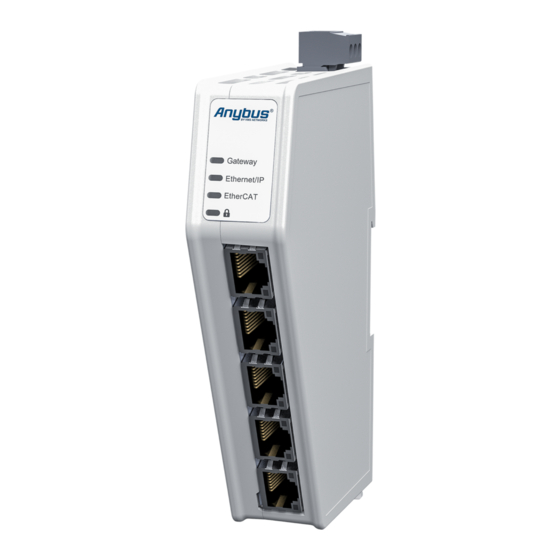
® ™ Anybus Communicator - EtherNet/IP to EtherCAT MDevice Installation 6. Installation 6.1. External Parts Figure 7. External parts A. Power connector E. EtherNet/IP port x 2 Security switch B. Label with LED designation EtherCAT (X3.1) port K. Factory reset button C. -
Page 17: Din Rail Mounting
® ™ DIN Rail Mounting Anybus Communicator - EtherNet/IP to EtherCAT MDevice 6.2. DIN Rail Mounting IMPORTANT The equipment must be electrically grounded through the DIN rail for EMC compliance. Make sure that the equipment is correctly mounted on the rail and that the rail is properly grounded. IMPORTANT To physically secure networks and equipment and to prevent unauthorized access, it is recommended to install the equipment in a locked environment. -
Page 18: Connect To Ethercat Network
® ™ Anybus Communicator - EtherNet/IP to EtherCAT MDevice Connect to EtherCAT Network 6.3. Connect to EtherCAT Network Figure 9. Connect to EtherCAT network 1. Connect the Communicator upper EtherCAT port X3.1 (A) to your EtherCAT network. NOTE The Communicator lower EtherCAT port X3.2 (B) is reserved for future use, do not use. EtherCAT Connector Description Not used... -
Page 19: Connect To Ethernet/Ip Network
® ™ Connect to EtherNet/IP Network Anybus Communicator - EtherNet/IP to EtherCAT MDevice 6.4. Connect to EtherNet/IP Network Figure 10. Connect to EtherNet/IP network 1. Connect the Communicator to your EtherNet/IP network. EtherCAT Connector Description Not used Not used Not used Not used To Do Next Connect the Communicator to the EtherCAT network and to power. -
Page 20: Connect To Power
® ™ Anybus Communicator - EtherNet/IP to EtherCAT MDevice Connect to Power 6.5. Connect to Power CAUTION Ensure that the power supply is turned off before connecting it to the equipment. IMPORTANT Using the wrong type of power supply can damage the equipment. Ensure that the power supply is connected properly and of the recommended type. -
Page 21: Security Switch
® ™ Security Switch Anybus Communicator - EtherNet/IP to EtherCAT MDevice 6.6. Security Switch IMPORTANT After completing the configuration of the Communicator, lock the security switch to prevent unauthorized access to the Communicator built-in web interface. When the security switch is in its locked position, the Communicator built-in web interface can not be accessed and the Communicator can not be configured using the built-in web interface. - Page 22 ® ™ Anybus Communicator - EtherNet/IP to EtherCAT MDevice Security Switch Security Switch Status LED Figure 13. Security switch locked status LED When the security switch is in its: • locked position, the security switch status LED turn solid green. •...
-
Page 23: Lock The Cables
® ™ Lock the Cables Anybus Communicator - EtherNet/IP to EtherCAT MDevice 6.7. Lock the Cables Figure 14. Lock the cables To strain relieve the cables, place a cable tie in the holder and lock the cables. SCM-1202-218 Version 1.0 Page 19 of 61... -
Page 24: Din Rail Demount
® ™ Anybus Communicator - EtherNet/IP to EtherCAT MDevice DIN Rail Demount 6.8. DIN Rail Demount Before You Begin IMPORTANT Be careful when removing the Communicator from the DIN-rail. If not removed properly, the DIN rail locking mechanism and the product cover can break. Have a flat-blade screwdriver, size 5.5 mm, available. - Page 25 ® ™ DIN Rail Demount Anybus Communicator - EtherNet/IP to EtherCAT MDevice Hold the screwdriver in the DIN rail locking mechanism while you unhook the Communicator from the DIN rail. Figure 16. Unhook the Communicator SCM-1202-218 Version 1.0 Page 21 of 61...
-
Page 26: Communicator Configuration
® ™ Anybus Communicator - EtherNet/IP to EtherCAT MDevice Communicator Configuration 7. Communicator Configuration 7.1. Connect the Communicator Procedure Connect to EtherCAT network and EtherNet/IP network Connect to PC and Power Connect an Ethernet cable between the Communicator and your PC. Connect the Communicator to a power supply. -
Page 27: Access The Built-In Web Interface From Hms Ipconfig
® ™ Access the Built-In Web Interface From HMS IPconfig Anybus Communicator - EtherNet/IP to EtherCAT MDevice 7.2. Access the Built-In Web Interface From HMS IPconfig Before You Begin Download the software application HMS IPconfig installation files and user documentation from www.anybus.com/support. - Page 28 ® ™ Anybus Communicator - EtherNet/IP to EtherCAT MDevice Access the Built-In Web Interface From HMS IPconfig To open the Open web page built-in web interface, click Communicator. Result You are redirected to the Communicator built-in web interface Home page. Page 24 of 61 SCM-1202-218 Version 1.0...
-
Page 29: Access The Built-In Web Interface From A Web Browser
® ™ Access the Built-In Web Interface From a Web Browser Anybus Communicator - EtherNet/IP to EtherCAT MDevice 7.3. Access the Built-In Web Interface From a Web Browser Before You Begin NOTE The Communicator configuration port default IP address is 192.168.0.10. NOTE To access the Communicator built-in web interface, ensure that Port 80 TCP is open in your Firewall. -
Page 30: Communicator Built-In Web Interface Overview
® ™ Anybus Communicator - EtherNet/IP to EtherCAT MDevice Communicator Built-In Web Interface Overview 7.4. Communicator Built-In Web Interface Overview Use the Communicator built-in web interface to configure, maintain and troubleshoot the Communicator. Figure 17. The Communicator built-in web interface Home page Menu item Description Home... -
Page 31: Ethercat Mdevice Settings
® ™ EtherCAT MDevice Settings Anybus Communicator - EtherNet/IP to EtherCAT MDevice 7.5. EtherCAT MDevice Settings 7.5.1. Cycle Time Settings Figure 18. Communication page, Cycle time Specify how often data is exchanged. A lower cycle time results in reduced latency and jitter but increased network load. •... -
Page 32: Ethercat Mdevice Scan
® ™ Anybus Communicator - EtherNet/IP to EtherCAT MDevice EtherCAT MDevice Settings 7.5.2. EtherCAT MDevice Scan Figure 19. EtherCAT MDevice page, Scan to import nodes Procedure To import the EtherCAT MDevice nodes, click Scan. The Select nodes window appears. By default, all nodes are selected. •... -
Page 33: Node Properties
® ™ EtherCAT MDevice Settings Anybus Communicator - EtherNet/IP to EtherCAT MDevice 7.5.3. Node Properties Figure 21. EtherCAT MDevice page, Properties To view the process data objects and the properties for a specific node, select the node in the list. The I/O data From the SubDevice to the MDevice and From the MDevice to the SubDevice are displayed in the Properties pane. -
Page 34: High Level Network Settings
® ™ Anybus Communicator - EtherNet/IP to EtherCAT MDevice High Level Network Settings 7.6. High Level Network Settings Configure the EtherNet/IP network settings. 7.6.1. To Use DHCP Server Figure 23. IP Settings, DHCP enabled To enable DHCP, select the DHCP enabled checkbox. The IP settings will be provided by the high level network DHCP server. -
Page 35: To Configure Ip Settings Manually
® ™ High Level Network Settings Anybus Communicator - EtherNet/IP to EtherCAT MDevice 7.6.2. To Configure IP Settings Manually Figure 24. IP Settings, DCHP disabled 1. Deselect the DHCP enabled checkbox. 2. Configure the IP settings. Setting Description IP address The EtherNet/IP network IP address in IPv4 dot-decimal notation Subnet mask The EtherNet/IP network Subnet mask in IPv4 dot-decimal notation. -
Page 36: Naming The Host
® ™ Anybus Communicator - EtherNet/IP to EtherCAT MDevice High Level Network Settings 7.6.4. Naming the Host Figure 26. IP Settings Hostname You can label the Communicator. • The maximum allowed length of the Hostname is 64 characters. • No symbol characters, punctuation characters, or whitespace are permitted. •... -
Page 37: I/O Data Map
® ™ I/O Data Map Anybus Communicator - EtherNet/IP to EtherCAT MDevice 7.7. I/O Data Map Figure 27. I/O data map page On the I/O data map page the data communication between the EtherCAT and the EtherNet/IP network is mapped. The allocated I/O area is auto-generated based on the scanned EtherCAT network node(s) configuration and how the settings on the EtherNet/IP page are configured. -
Page 38: Endian Swap
® ™ Anybus Communicator - EtherNet/IP to EtherCAT MDevice I/O Data Map 7.7.1. Endian Swap Figure 28. I/O data map, Endian swap To change the byte order: Navigate to the I/O data map page. In the data map, select the object for which you want to do swap the byte order. Select the endian swap type from the Endian swap drop-down menu. -
Page 39: Live List
® ™ I/O Data Map Anybus Communicator - EtherNet/IP to EtherCAT MDevice 7.7.2. Live List Figure 29. I/O data map page, Live list enabled By default Live list is disabled. When Live list is enabled, the first four bytes of process data on the EtherNet/IP network contain the live list. Each bit in the Live list can hold the status for one node. -
Page 40: Data Exchange Control
® ™ Anybus Communicator - EtherNet/IP to EtherCAT MDevice I/O Data Map 7.7.3. Data Exchange Control Figure 30. I/O data map, Data exchange control enabled By default Data exchange control is disabled. When Data exchange control is enabled, the first four bytes of process data on the EtherNet/IP network contain the data exchange control. -
Page 41: Configuration Notes
® ™ Configuration Notes Anybus Communicator - EtherNet/IP to EtherCAT MDevice 7.8. Configuration Notes You can add notes to describe the Communicator configuration. 7.8.1. Add Configuration Note Procedure To open the Configuration Notes window, click on the comments icon Figure 31. Configuration note, comment icon To add a new configuration note, click Add. - Page 42 ® ™ Anybus Communicator - EtherNet/IP to EtherCAT MDevice Configuration Notes Write your configuration note and click accept Figure 33. Write a configuration note The configuration note is added to the list. To close the window, click close To save the configuration note, click Apply in the web-interface header, and follow the instructions. Page 38 of 61 SCM-1202-218 Version 1.0...
-
Page 43: View And Edit Configuration Notes
® ™ Configuration Notes Anybus Communicator - EtherNet/IP to EtherCAT MDevice 7.8.2. View and Edit Configuration Notes To view and/or edit a note, click on the comments icon Figure 34. Example: The comment icon indicates that there are three added notes The configuration notes are listed in the Configuration Note window. -
Page 44: Apply Configuration
® ™ Anybus Communicator - EtherNet/IP to EtherCAT MDevice Apply Configuration 7.9. Apply Configuration Before You Begin NOTE When you apply the configuration, any existing configuration is overwritten. Figure 36. Disconnect the Communicator from the networks Before you can apply the configuration, ensure that there is no active communication on the EtherNet/IP network where the Communicator is connected. -
Page 45: To Use An Existing Configuration
® ™ To Use an Existing Configuration Anybus Communicator - EtherNet/IP to EtherCAT MDevice 7.10. To Use an Existing Configuration When you have configured a Communicator and want to use the same settings to configure additional Communicator, do the following. Procedure Figure 37. -
Page 46: Plc Configuration
® ™ Anybus Communicator - EtherNet/IP to EtherCAT MDevice PLC Configuration 8. PLC Configuration 8.1. Export Product EDS File Option if the PLC program requires a product file, EDS (Electronic Data Sheet) file, describing how the Communicator can be used on the high level network. Figure 38. -
Page 47: Verify Operation
® ™ Verify Operation Anybus Communicator - EtherNet/IP to EtherCAT MDevice 9. Verify Operation Before You Begin Ensure that the Communicator is connected to your PC, to a power supply and to the OT network. Installation (page 12). 9.1. Communicator Status Monitor On the Home page, you can get a quick overview of the network and the Communicator operating status. - Page 48 ® ™ Anybus Communicator - EtherNet/IP to EtherCAT MDevice Communicator Status Monitor Status Symbols Symbol Description Internal error has occurred and operation cannot be guaranteed. Out of Specification. Check Function: • Initial state where non network components are started and configured. •...
-
Page 49: Communicator Led Indicators
® ™ Communicator LED Indicators Anybus Communicator - EtherNet/IP to EtherCAT MDevice 9.2. Communicator LED Indicators This topic applies to different product variants for different networks. NOTE Before you can verify operation you must configure the Communicator. Figure 40. Gateway status (A), Network connection (B)/(C) and Security switch (D) Gateway status - LED A Operation status Description... -
Page 50: Ethercat Led Indicators
® ™ Anybus Communicator - EtherNet/IP to EtherCAT MDevice EtherCAT LED Indicators EtherCAT MDevice • LED C for product: ABC3107 EtherNet/IP, ABC3128 Modbus TCP, ABC3113 PROFINET, and ABC3190 Common Ethernet • LED B for product: ABC3100 PROFIBUS Operation status Description No power/Subnetwork not running/Node is switched off via a control word Green, solid Running... -
Page 51: Maintenance
® ™ Maintenance Anybus Communicator - EtherNet/IP to EtherCAT MDevice 10. Maintenance 10.1. Configuration File Handling 10.1.1. Export Configuration You can export the current configuration, in order to import and use the same settings to configure additional Communicator. Figure 42. Files & firmware page To export a configuration file: •... -
Page 52: Import Configuration
® ™ Anybus Communicator - EtherNet/IP to EtherCAT MDevice Configuration File Handling 10.1.2. Import Configuration To easily configure multiple Communicator with the same settings, you can import a configuration file. Before You Begin The supported file format is .conf. Procedure Figure 43. -
Page 53: Clear And Revert Configuration
® ™ Clear and Revert Configuration Anybus Communicator - EtherNet/IP to EtherCAT MDevice 10.2. Clear and Revert Configuration You can restore all settings in a configuration to the default settings. Procedure Figure 44. Files & firmware page To Clear the Configuration When you want to clear a configuration and return to the default settings. -
Page 54: Firmware Management
® ™ Anybus Communicator - EtherNet/IP to EtherCAT MDevice Firmware Management 10.3. Firmware Management 10.3.1. View the Firmware Version On the Support page, you can view the current applied firmware version. Figure 45. Support page, Product information example 10.3.2. Firmware and Configuration Compatibility Compatibility after firmware upgrade Current configuration is still compatible after upgrading the firmware. -
Page 55: Update Firmware
® ™ Firmware Management Anybus Communicator - EtherNet/IP to EtherCAT MDevice 10.3.4. Update Firmware Before You Begin IMPORTANT To eliminate the risk of interference with plant operation, firmware update is only available when the Communicator is disconnected from the OT networks. Ensure that the Communicator is disconnected from the OT networks. -
Page 56: Change Language
® ™ Anybus Communicator - EtherNet/IP to EtherCAT MDevice Change Language 10.4. Change Language Default language is English. To change the language of the Communicator built-in web interface: In the Communicator built-in web-interface header, click the Language icon Figure 47. Language menu Select a new language from the list. -
Page 57: Troubleshooting
® ™ Troubleshooting Anybus Communicator - EtherNet/IP to EtherCAT MDevice 11. Troubleshooting 11.1. Diagnostics 11.1.1. I/O Data On the Diagnostics, I/O data page you can monitor how the data flow between the EtherCAT side and the EtherNet/IP side, including any configured endian conversions. Figure 49. -
Page 58: Event Log
® ™ Anybus Communicator - EtherNet/IP to EtherCAT MDevice Diagnostics 11.1.2. Event Log Figure 50. Event log page example How To Analyze the Information The log follows the FIFO principle, first in and first out. The oldest (first) value is processed first. Time (d:hh:mm:ss.ms) The date and time when the event occurred. -
Page 59: Led Status
® ™ Diagnostics Anybus Communicator - EtherNet/IP to EtherCAT MDevice 11.1.3. LED Status On the Home page, you can remotely monitor the Communicator LED status. Figure 51. Home page For information about the LED indication, see Communicator LED Indicators. SCM-1202-218 Version 1.0 Page 55 of 61... -
Page 60: Reset To Factory Settings
® ™ Anybus Communicator - EtherNet/IP to EtherCAT MDevice Reset to Factory Settings 11.2. Reset to Factory Settings Before You Begin Procedure To reset the Communicator: Disconnect the Communicator from power. Figure 52. Disconnect power Use a pointed object, such as a ballpoint pen to press and hold the Reset button. Figure 53. - Page 61 ® ™ Reset to Factory Settings Anybus Communicator - EtherNet/IP to EtherCAT MDevice While holding the reset button, reconnect the Communicator to power. Figure 54. Hold Reset button and reconnect power Release the reset button. The Communicator enters exception state. Reboot the Communicator.
-
Page 62: Firmware Upgrade Error Management
® ™ Anybus Communicator - EtherNet/IP to EtherCAT MDevice Firmware Upgrade Error Management 11.3. Firmware Upgrade Error Management If the firmware update process is interrupted or if the power is lost during the update process, the Communicator goes into fallback mode. The last working firmware is still available on the flash, but it is not active. - Page 63 ® ™ Firmware Upgrade Error Management Anybus Communicator - EtherNet/IP to EtherCAT MDevice Leave the Communicator for 10 minutes. The Gateway status led indicator flashes red and green until the firmware upgrade is completed. Figure 58. Firmware upgrade LED indication Result The Communicator recover and return to normal operation.
-
Page 64: Support
® ™ Anybus Communicator - EtherNet/IP to EtherCAT MDevice Support 11.4. Support 11.4.1. Support Package Figure 60. Support page example Before you create a ticket for technical support, generate a support package. The support package contains information about what has occurred and will help the Anybus technical support team resolve the support case as quickly and efficiently as possible. -
Page 65: Technical Data
® ™ Technical Data Anybus Communicator - EtherNet/IP to EtherCAT MDevice 12. Technical Data For complete technical specifications and regulatory compliance information, please visit www.anybus.com. 12.1. Technical Specifications Article identification ABC3107 Configuration connector RJ45 Communication connector RJ45 x 2 EtherCAT MDevice connector RJ45 x 2 Power connector 3-pin screw connector...
Need help?
Do you have a question about the Anybus Communicator and is the answer not in the manual?
Questions and answers