HMS Networks Intesis IN770AIR00XO000 User Manual
Hide thumbs
Also See for Intesis IN770AIR00XO000:
- Manual (45 pages) ,
- User manual (44 pages) ,
- User manual (37 pages)

Related Manuals for HMS Networks Intesis IN770AIR00XO000


Summary of Contents for HMS Networks Intesis IN770AIR00XO000
- Page 1 ENGLISH Hitachi VRF with KNX, Serial and IP support IN770AIR00XO000 GATEWAY USER MANUAL Version 1.0.6 Publication date 2023-11-17...
- Page 2 The information in this document shall therefore not be construed as a commitment on the part of HMS Networks and is subject to change without notice. HMS Networks makes no commitment to update or keep current the information in this document.
-
Page 3: Table Of Contents
Hitachi VRF with KNX, Serial and IP support Table of Contents 1. Description and Order Codes ..................... 1 2. Licensing ..........................2 3. General Information ........................ 3 3.1. Intended Use of the User Manual ..................3 3.2. General Safety Information ....................3 3.3. -
Page 4: Description And Order Codes
Description and Order Codes Hitachi VRF with KNX, Serial and IP support 1. Description and Order Codes IN770AIR00xO000 Gateway. Modbus®, KNX®, BACnet®, and Home Automation® gateway for Hitachi® air conditioning systems. ORDER CODE LEGACY ORDER CODE INBACHIT016O000 INBACHIT064O000 IN770AIR00xO000 INKNXHIT016O000 INKNXHIT064O000 INMBSHIT016O000 INMBSHIT064O000 The x stands for S or M, depending on the license you have purchased. -
Page 5: Licensing
Hitachi VRF with KNX, Serial and IP support Licensing 2. Licensing Distribution license(s) for the IN770AIR00xO000 gateway: Maximum AC units Order Code License Indoor units Outdoor units IN770AIR00SO000 Small IN770AIR00MO000 Medium NOTE The order code may vary depending on the product seller and the buyer's location. Page 2 of 38 USER MANUAL Version 1.0.6... -
Page 6: General Information
General Information Hitachi VRF with KNX, Serial and IP support 3. General Information 3.1. Intended Use of the User Manual This manual contains the main features of this Intesis gateway and the instructions for its appropriate installation, configuration, and operation. The contents of this manual should be brought to the attention of any person who installs, configures, or operates this gateway or any associated equipment. - Page 7 Hitachi VRF with KNX, Serial and IP support Admonition Messages and Symbols IMPORTANT Instruction that must be followed to avoid a risk of reduced functionality and/or damage to the equipment or to avoid a network security risk. NOTE Additional information which may facilitate installation and/or operation. Helpful advice and suggestions.
-
Page 8: Overview
Overview Hitachi VRF with KNX, Serial and IP support 4. Overview This IN770AIR00xO000 gateway supports four applications. Gateway's client interface ↔ Gateway's server interface Modbus TCP and RTU KNX TP Hitachi VRF HVAC systems BACnet/IP or MS/TP Home Automation IMPORTANT This document assumes that the user is familiar with these technologies. -
Page 9: Inside The Package
Figure 3. Integration of Hitachi AC systems into BACnet installations Figure 4. Integration of Hitachi AC systems into Home Automation installations 4.1. Inside the Package Items included: • Intesis IN770AIR00xO000 Gateway • USB Mini-B type to USB Type-A cable • Installation sheet 4.2. Main Features •... -
Page 10: Gateway General Functionality
10). 4.3. Gateway General Functionality With this Intesis IN770AIR00xO000 gateway, you can easily integrate Hitachi VRF systems into an installation based on Modbus TCP, Modbus RTU, KNX, BACnet/IP, BACnet MS/TP, or Home Automation. To do so, the gateway acts as a server device of the installation itself, accessing all signals from each air conditioner unit and controlling the whole AC network. -
Page 11: Hardware
Hitachi VRF with KNX, Serial and IP support Hardware 5. Hardware 5.1. Mounting IMPORTANT Before mounting, please ensure that the chosen installation place preserves the gateway from direct solar radiation, water, high relative humidity, or dust. IMPORTANT Maximum mounting height: below 2 meters (6.5 feet). NOTE Mount the gateway on a wall or over a DIN rail. - Page 12 Mounting Hitachi VRF with KNX, Serial and IP support DIN rail mounting Fit the gateway’s top-side clips in the upper edge of the DIN rail. Press the low side of the gateway gently to lock it in the DIN rail. Make sure the gateway is firmly fixed.
-
Page 13: Connection
Hitachi VRF with KNX, Serial and IP support Connection 5.2. Connection CAUTION Disconnect all systems from power before manipulating and connecting them to the gateway. IMPORTANT Keep communication cables away from power and ground wires. 5.2.1. Gateway Connectors Figure 5. Wiring diagram Page 10 of 38 USER MANUAL Version 1.0.6... - Page 14 Connection Hitachi VRF with KNX, Serial and IP support Connectors' wiring: IMPORTANT For all connectors, use solid or stranded wires (twisted or with ferrule). Cross-section/gauge per terminal: • One core: 0.2 .. 2.5 mm / 24 .. 11 AWG • Two cores: 0.2 .. 1.5 mm / 24 ..
-
Page 15: Connection Procedure For The Ac Unit
Hitachi VRF with KNX, Serial and IP support Connection IMPORTANT • When using a DC power supply: Respect the polarity labeled on the power connector for the positive and negative wires. • When using an AC power supply: Ensure the same power supply is not powering any other device. -
Page 16: Connection Procedure For Knx
Connection Hitachi VRF with KNX, Serial and IP support For Modbus RTU: Connect the Modbus RTU communication cable to the gateway's EIA-485 port. The connector for the EIA-485 bus is a green pluggable terminal block labeled SG (signal ground), B-, and A+. IMPORTANT Observe polarity. -
Page 17: Connection Procedure For Bacnet
Hitachi VRF with KNX, Serial and IP support Connection 5.2.5. Connection Procedure for BACnet For BACnet/IP: Connect the BACnet/IP Ethernet cable to the gateway's Ethernet Port. The correct cable to use depends on where the gateway is connected: • Connecting directly to a BACnet/IP device: use a crossover Ethernet UTP/FTP CAT5 or higher cable. •... -
Page 18: Connection Procedure For Home Automation
Connection Hitachi VRF with KNX, Serial and IP support IMPORTANT When installing the gateway at the end of the bus with the termination resistor enabled, do not install an additional termination resistor at that end. NOTE See the Wiring diagram (page 10). -
Page 19: Gateway Layout
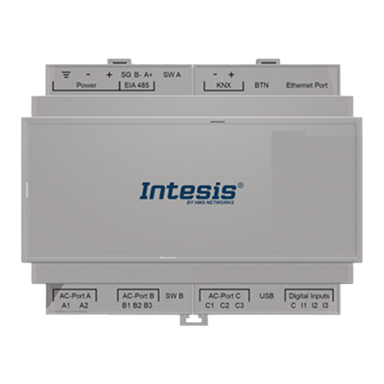
Hitachi VRF with KNX, Serial and IP support Gateway Layout 5.3. Gateway Layout Figure 6. Disposition of hardware elements in the gateway Plastic covers numbered in the image as ①, ②, ③, and ④ can be easily disassembled. The following sections explain each element in more detail: LEDs, DIP switches, and the push button. Page 16 of 38 USER MANUAL Version 1.0.6... -
Page 20: Led Indicators
LED Indicators Hitachi VRF with KNX, Serial and IP support 5.4. LED Indicators Table 1. LEDs location and behavior Cover Color Description Top side LED 1 (PWR) Green Power on (not programmable) LED 2 (ERR) Blinking: Hardware error Under frontal cover ① LED 3 Green 485 Tx (RS485 for BACnet or Modbus) -
Page 21: Push Button
Hitachi VRF with KNX, Serial and IP support Push Button 5.6. Push Button Find the push button at the top side, between the KNX and the Ethernet connectors (see the figure Disposition of hardware elements in the gateway (page 16)). NOTE The button is hidden and only accessible using a thin object like a paper clip. -
Page 22: Technical Specifications
Technical Specifications Hitachi VRF with KNX, Serial and IP support 5.7. Technical Specifications Plastic, type PC (UL 94 V-0). Color: Light Grey. RAL 7035 Net dimensions (dxwxh): Millimeters: 90 x 106 x 58 mm / Inches: 3.5 x 4.2 x 2.3" Housing Recommended space for installation (dxwxh): Millimeters: 130 x 115 x 100 mm / Inches: 5.1 x 4.5 x3.9"... -
Page 23: Dimensions
Hitachi VRF with KNX, Serial and IP support Dimensions 5.8. Dimensions • Net dimensions (DxWxH) Millimeters: 90 x 106 x 58 mm Inches: 3.5 x 4.2 x 2.3" • Clear space for installation (DxWxH) Millimeters: 130 x 115 x 100 mm Inches: 5.1 x 4.5 x 3.9"... -
Page 24: Available Applications
Available Applications Hitachi VRF with KNX, Serial and IP support 6. Available Applications NOTE Signals marked as Optional signals are supported by the gateway but may not be supported by the server devices of the installation. Please refer to the technical documentation of each server device to know which signals they support. - Page 25 Hitachi VRF with KNX, Serial and IP support Integration into Modbus Systems Register name Possible values Modbus address Fan Speed High+ (all the units) 1: Set Fan Speed High+ Trigger Air louver Auto (all the units) 1: Set Air louver Position Auto Trigger Air louver 1 (all the units) 1: Set Air louver Position 1...
- Page 26 Integration into Modbus Systems Hitachi VRF with KNX, Serial and IP support Register name Possible values Modbus address formula Celsius: -63 .. 63°C Inlet Temp. (x10°C) (IU address[0 .. 63]*100)+6 Celsius: -81 .. 145°F Celsius: -63 .. 63°C Outlet Temp. (x10°C) (IU address[0 ..
- Page 27 Hitachi VRF with KNX, Serial and IP support Integration into Modbus Systems Register name Possible values Modbus address formula Consumption Yesterday Heat Wh/KWh (IU address[0 .. 63]*100)+34 Consumption Today Heat Wh/KWh (IU address[0 .. 63]*100)+36 Consumption Total Heat Wh/KWh (IU address[0 .. 63]*100)+38 Consumption Yesterday Cool Wh/KWh (IU address[0 ..
-
Page 28: Integration Into Knx Systems
Integration into KNX Systems Hitachi VRF with KNX, Serial and IP support 6.2. Integration into KNX Systems 6.2.1. KNX Signals The following tables list all available KNX signals for this gateway. NOTE Physical Address: The gateway supports (P/S) and (P/I/S) format levels. NOTICE Communication object flags: •... - Page 29 Hitachi VRF with KNX, Serial and IP support Integration into KNX Systems Table 6. Outdoor units signals Object name Possible values Flags 0: No error Status_Communication Error OU 1.005-DPT_Alarm (1bit) R, T 1: Error Celsius: -50 .. 99 °C Status_Outdoor Air Temperature (°C) 9.001-DPT_Value_Temp (2byte) R, T Fahrenheit: -58 ..
- Page 30 Integration into KNX Systems Hitachi VRF with KNX, Serial and IP support Object name Possible values Flags Control_Heat mode 1: Set heat mode 1.001-DPT_Switch (1bit) Ri, W, U 1: Heat mode active Status_Heat mode 1.001-DPT_Switch (1bit) R, T 0: Heat mode not active Control_Cool mode 1: Set cool mode 1.001-DPT_Switch (1bit)
- Page 31 Hitachi VRF with KNX, Serial and IP support Integration into KNX Systems Object name Possible values Flags Thersholds: 0 .. 21 % 22 .. 36 % 37 .. 50 % Control_Vane position scaling 5.001-DPT_Scaling (1byte) Ri, W, U 51 .. 64 % 65 ..
- Page 32 Integration into KNX Systems Hitachi VRF with KNX, Serial and IP support Object name Possible values Flags Celsius: -63 .. 63 °C Status_Outlet Temperature 9.001-DPT_Value_Temp (2byte) R, T Fahrenheit: -81 .. 145°F Celsius: -63 .. 63 °C Status_GasPipe Temperature 9.001-DPT_Value_Temp (2byte) R, T Fahrenheit: -81 ..
- Page 33 Hitachi VRF with KNX, Serial and IP support Integration into KNX Systems Object name Possible values Flags 0: Off 1: Thermo Off Status_Operation condition 5.x (1byte) R, T 2: Thermo On 3: Alarm Celsius: -63 .. 63 °C Status_RC SW Temperature 9.001-DPT_Value_Temp (2byte) R, T Fahrenheit: -81 ..
-
Page 34: Integration Into Bacnet Systems
Integration into BACnet Systems Hitachi VRF with KNX, Serial and IP support 6.3. Integration into BACnet Systems NOTICE You can see the Protocol Implementation Conformance Statement (PICS) document on https:// www.intesis.com/docs/bacnet-client-pic-statement-770 6.3.1. BACnet Objects NOTICE This part is common for BACnet MS/TP and BACnet/IP. Input object types: •... - Page 35 Hitachi VRF with KNX, Serial and IP support Integration into BACnet Systems Object name Possible values Object type Object instance OUXX_Total Real Comp. Freq. 0 .. 255 Hz 0-Analog Input (OU address × 25) + 20000 + 2 OUXX_Total Comp. Current 0 ..
- Page 36 Integration into BACnet Systems Hitachi VRF with KNX, Serial and IP support Object name Possible values Object type Object instance Celsius: -63 .. 63°C OXXUXX_LiquidPipe Temp. 0-Analog Input (IU address × 100) + 5 Fahrenheit: -81 .. 145°F OXXUXX_Unit Error code Error code 0-Analog Input (IU address ×...
- Page 37 Hitachi VRF with KNX, Serial and IP support Integration into BACnet Systems Object name Possible values Object type Object instance 0: Without RCS OXXUXX_RC SW Config 3-Binary Input (IU address × 100) + 8 1: With RCS OXXUXX_Consumption Yesterday_S Wh/KWh 0-Analog Input (IU address ×...
-
Page 38: Integration Into Home Automation Systems
Integration into Home Automation Systems Hitachi VRF with KNX, Serial and IP support 6.4. Integration into Home Automation Systems 6.4.1. Home Automation Signals The following tables list all available Home Automation signals for this gateway. NOTE • SET: Command used to control the indoor unit. It is sent by the client. •... -
Page 39: Late Configuration: Change The Gateway's Protocol
Hitachi VRF with KNX, Serial and IP support Late Configuration: Change the Gateway's Protocol 7. Late Configuration: Change the Gateway's Protocol Reconfiguring the gateway with a different protocol is very easy: Connect the gateway to the PC and open the configuration tool Intesis MAPS. Select the new template you need. -
Page 40: Error Codes
Error Codes Hitachi VRF with KNX, Serial and IP support 8. Error Codes NOTE These error codes are the same for all applications. Error Code Error Category Description Intesis gateway No Communication Error OU Activation of Protection Device (Float Switch). Activation of Float Switch (High Water Level in Drain Pan, Indoor unit Abnormality of Drain Pipe, Float Switch or Drain Pan) Activation of Protection Device (High Pressure Cut). - Page 41 Hitachi VRF with KNX, Serial and IP support Error Codes Error Code Error Category Description lncorrect Setting of Outdoor Unit Models Combination or Voltage. lncorrect Setting of Main and Sub Unit(s) Combination or Voltage. Abnormality Transmission between Main Unit and Sub Unit(s). lncorrect Wiring, Disconnect Wire, Breaking Wire, PCB Failure.
Need help?
Do you have a question about the Intesis IN770AIR00XO000 and is the answer not in the manual?
Questions and answers