
Related Manuals for HMS Networks Anybus AWB5300


Summary of Contents for HMS Networks Anybus AWB5300
- Page 1 ENGLISH ® Anybus Tunnel Gateway STARTUP GUIDE SP3196 Version 1.0 Publication date 2024-07-09...
- Page 2 The information in this document shall therefore not be construed as a commitment on the part of HMS Networks and is subject to change without notice. HMS Networks makes no commitment to update or keep current the information in this document.
-
Page 3: About This Document
® Preface Anybus Tunnel Gateway 1. Preface 1.1. About This Document ® This document describes how to install Anybus Tunnel Gateway. For additional documentation and software downloads, FAQs, troubleshooting guides and technical support, please visit www.hms-networks.com. 1.2. Document Conventions Safety Symbols DANGER Instructions that must be followed to avoid an imminently hazardous situation which, if not avoided, will result in death or serious injury. -
Page 4: Information Symbols
Additional information which may facilitate installation and/or operation. Helpful advice and suggestions. 1.3. Trademarks ® Anybus is a registered trademark of HMS Networks. All other trademarks mentioned in this document are the property of their respective holders. Page 2 of 20 SP3196 Version 1.0... -
Page 5: General Safety
® Safety Anybus Tunnel Gateway 2. Safety 2.1. General Safety CAUTION Connecting power with reverse polarity or using the wrong type of power supply may damage the equipment. Make sure that the power supply is connected correctly and of the recommended type. CAUTION This equipment contains parts that can be damaged by electrostatic discharge (ESD). - Page 6 ® Anybus Tunnel Gateway Preparation 3. Preparation 3.1. Support and Resources For additional documentation and software downloads, FAQs, troubleshooting guides and technical support, please visit www.hms-networks.com. Have the product article number available, to search for the product specific support web page. You find the product article number on the product cover.
-
Page 7: Installation
® Installation Anybus Tunnel Gateway 4. Installation 4.1. DIN Rail Mounting Before You Begin IMPORTANT The equipment must be electrically grounded through the DIN rail for EMC compliance. Make sure that the equipment is correctly mounted on the rail and that the rail is properly grounded. Have a flat-blade screwdriver, size 5.5 mm, available. - Page 8 ® Anybus Tunnel Gateway Connect to 5G Core (5GC) Network To attach the Tunnel Gateway on the DIN rail: Insert the upper end of the DIN rail clip into the DIN rail. Insert the screwdriver into the DIN rail clip tab A. Pull and hold the DIN rail clip tab A downwards.
-
Page 9: Ethernet Rj45 Connector Pinout
® Connect to 5G Core (5GC) Network Anybus Tunnel Gateway Ethernet RJ45 Connector Pinout Ethernet RJ45 Connector Description Not used Not used Not used Not used SP3196 Version 1.0 Page 7 of 20... - Page 10 ® Anybus Tunnel Gateway Connect Ethernet Devices 4.3. Connect Ethernet Devices When configuring the Tunnel Gateway, use one of the LAN switch ports to connect to your PC. Figure 3. LAN switch ports, ETH 1-4 Connect your Ethernet device(s) to the Tunnel Gateway LAN switch ports ETH 1-4. Page 8 of 20 SP3196 Version 1.0...
- Page 11 ® Connect Ethernet Devices Anybus Tunnel Gateway Ethernet RJ45 Connector Pinout Ethernet RJ45 Connector Description Not used Not used Not used Not used SP3196 Version 1.0 Page 9 of 20...
-
Page 12: Connect To Power
® Anybus Tunnel Gateway Connect to Power 4.4. Connect to Power Before You Begin CAUTION Ensure that the power supply is turned off before connecting it to the equipment. CAUTION Connecting power with reverse polarity or using the wrong type of power supply may damage the equipment. -
Page 13: Power Connector Pinout
® Connect to Power Anybus Tunnel Gateway Power Connector Pinout Power port Description Voltage Common Collector (VCC) 24 VDC Ground (GND) Functional Earth (FE) Procedure Figure 4. Connect to power SP3196 Version 1.0 Page 11 of 20... - Page 14 ® Anybus Tunnel Gateway DIN Rail Demount Insert the cable wires to the terminal block and tighten the wire clamp screws. Connect the terminal block to the Tunnel Gateway. Connect the Tunnel Gateway to a power supply. Turn on the power supply. 4.5.
- Page 15 ® Configuration Anybus Tunnel Gateway 5. Configuration 5.1. Connect to Configure 5.1.1. Connect to PC and Power When configuring the Tunnel Gateway it must be connected to a PC. Figure 6. Connect to PC and power Connect an Ethernet cable between one of the Tunnel Gateway LAN switch ports and your PC.
- Page 16 ® Anybus Tunnel Gateway Required IP Address Settings 5.2. Required IP Address Settings NOTE The Tunnel Gateway default IP address is 192.168.1.96 and the subnet mask is 255.255.255.0. Set a Static IP Address on Your PC On the PC accessing the Tunnel Gateway built-in web interface, configure the Ethernet interface settings as follows: Setting Value...
- Page 17 ® Login to the Built-In Web Interface Anybus Tunnel Gateway 5.3. Login to the Built-In Web Interface The Tunnel Gateway built-in web interface can be accessed from a standard web browser. Before You Begin IMPORTANT For cybersecurity reasons, you are prompted to change the password at first login using the Tunnel Gateway factory default password.
- Page 18 ® Anybus Tunnel Gateway Login to the Built-In Web Interface The Tunnel Gateway built-in web interface login screen appears. Enter Username and Password and click Login. Figure 8. Built-in web interface login screen Result You are logged in to the Tunnel Gateway built-in web interface Home page. Page 16 of 20 SP3196 Version 1.0...
- Page 19 ® Configure the Tunnel Gateway Anybus Tunnel Gateway 5.4. Configure the Tunnel Gateway Procedure Figure 9. The Tunnel Gateway built-in web interface Home page Open the Tunnel Gateway built-in web interface in HMS IPconfig or enter the Tunnel Gateway IP address in your web browser. The built-in web interface takes you through the steps to configure the Tunnel Gateway.
-
Page 20: Technical Specification
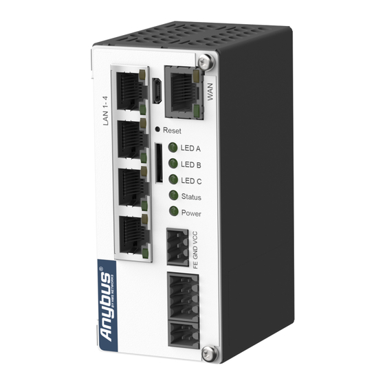
® Anybus Tunnel Gateway Technical Specification 6. Technical Specification Article identification AWB5300 Ethernet connector Ethernet 100 Mbps x 5 Power connector 24 VDC, BL 3.50/03 connector +-15% Power supply 24 V (9 - 32 VDC), 1.5 A Power Supply The power supply must be a regulated limited power source (LPS) according to IEC/EN 62368-1, Annex Q, or IEC/EN 60950-1, clause 2.5 Current consumption Maximum: 0.4 A... - Page 21 ® Tunnel Gateway LED Indicators Anybus Tunnel Gateway 7. Tunnel Gateway LED Indicators Tunnel Gateway Operation Description Indicator Status LED A For future use. LED B For future use. LED C For future use. Status Reset/Reboot function is inactive. Green Reboot function is active.
-
Page 22: Ethernet Led Indication
® Anybus Tunnel Gateway Ethernet LED Indication 8. Ethernet LED Indication Figure 10. RJ45 LED indicators LED A – LINK Function No Ethernet link or no power Yellow Ethernet link established Yellow, flashing Ethernet traffic LED B – ACTIVITY Function No power Green Power on...
Need help?
Do you have a question about the Anybus AWB5300 and is the answer not in the manual?
Questions and answers