Emerson Rosemount 5408 Quick Start Manual
Level transmitter with modbus protocol
Hide thumbs
Also See for Rosemount 5408:
- Reference manual (274 pages) ,
- All-in-one quick start manual (44 pages) ,
- Quick start manual (37 pages)

Related Manuals for Emerson Rosemount 5408


Summary of Contents for Emerson Rosemount 5408
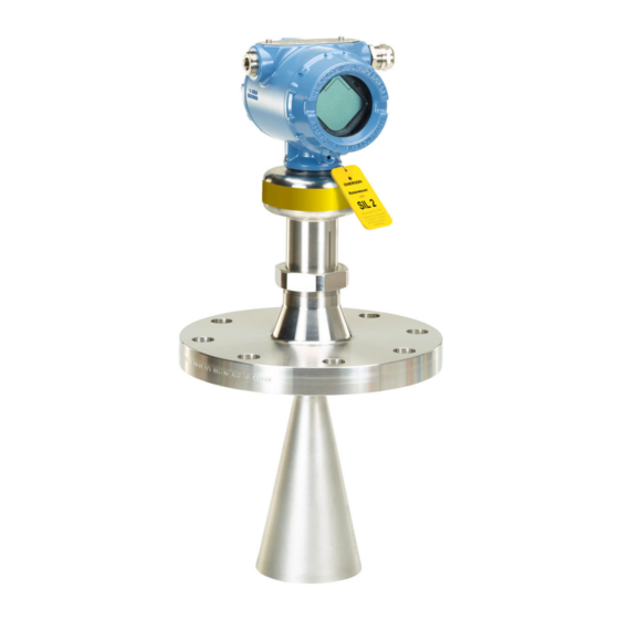
- Page 1 Quick Start Guide 00825-0800-4408, Rev AA February 2020 ™ Rosemount 5408 Level Transmitter ® with Modbus Protocol...
-
Page 2: Table Of Contents
Adjust the inclination of the antenna..................11 Plug and seal the air purge entry....................14 Adjust display orientation (optional)..................15 Prepare the electrical connections....................16 Connect wiring and power up.....................19 Performance specifications......................23 Functional specifications......................25 Physical specifications........................ 27 Rosemount 5408 Level Transmitter... -
Page 3: About This Guide
February 2020 Quick Start Guide About this guide This Quick Start Guide provides basic guidelines for the Rosemount 5408 ® Level Transmitter with Modbus Protocol. WARNING Failure to follow safe installation and servicing guidelines could result in death or serious injury. - Page 4 This is true for all systems used within the facility. CAUTION Hot surfaces The flange and process seal may be hot at high process temperatures. Allow to cool before servicing. Rosemount 5408 Level Transmitter...
-
Page 5: Confirm Approval Type
February 2020 Quick Start Guide Confirm approval type For hazardous locations transmitters labeled with multiple approval types: Procedure Permanently mark the checkbox of the selected approval type(s). Figure 2-1: Label with Multiple Approval Types Quick Start Guide... -
Page 6: Components Of The Parabolic Antenna
Components of the threaded version Figure 3-1: Components A. Antenna B. Purge plug kit (blind plug and bonded seal) C. Threaded sleeve D. M20 adapter E. Lock nut BSPP (G) 3½-in. F. Antenna adapter with ball joint G. O-ring Rosemount 5408 Level Transmitter... -
Page 7: Mount The Transmitter
February 2020 Quick Start Guide Mount the transmitter Mount the threaded version Procedure 1. Remove the lock nut. 2. Mount the O-ring. 3. Mount the antenna adapter on the mounting flange plate. Ensure the antenna adapter fits tightly to the mounting flange plate. A. - Page 8 Quick Start Guide February 2020 4. Remove the M20 adapter and visually inspect the O-rings for damage and dirt. 5. Carefully insert the antenna. 6. Secure the antenna. Torque 180 in-lb (20 N-m) 27 mm Rosemount 5408 Level Transmitter...
- Page 9 February 2020 Quick Start Guide 7. Tighten the set screw. Torque 5 in-lb (0.5 N-m) H2 mm 8. Position the antenna assembly onto the mounting frame. Example Deck/platform mounted 9. Tighten the bolts and nuts. It is recommended that insulating bushes are fitted to the mounting bolts.
- Page 10 Quick Start Guide February 2020 Postrequisites 1. Adjust the inclination of the antenna (see Adjust the inclination of antenna). 2. Plug and seal the air purge entry (see Plug and seal the air purge entry). Rosemount 5408 Level Transmitter...
-
Page 11: Adjust The Inclination Of The Antenna
February 2020 Quick Start Guide Adjust the inclination of the antenna Prerequisites WARNING Contents may be under pressure. • Do not loosen the M8 screws while in operation. Attempting to do so may release pressurized gases, resulting in serious injury or death. Procedure 1. - Page 12 Quick Start Guide February 2020 3. Place the supplied circular level on top of the antenna assembly. 4. Adjust the inclination of the antenna. 5. Gradually tighten the M8 screws. Torque 65 in-lb (7 N-m) H6 mm Rosemount 5408 Level Transmitter...
- Page 13 February 2020 Quick Start Guide 6. Remove the circular level. 7. Mount the transmitter head. Align the marking on the sensor module with the air purge connection. Torque 355 in-lb (40 N-m) 60 mm 36 mm Quick Start Guide...
-
Page 14: Plug And Seal The Air Purge Entry
Quick Start Guide February 2020 Plug and seal the air purge entry Procedure Plug and seal the entry with the supplied blind plug and bonded seal. Torque 180 in-lb (20 N-m) 17 mm Rosemount 5408 Level Transmitter... -
Page 15: Adjust Display Orientation (Optional)
February 2020 Quick Start Guide Adjust display orientation (optional) To improve field access to wiring or to better view the optional LCD display: Prerequisites Note In high vibration applications, the transmitter housing must be fully engaged into the sensor module to meet the vibration test specifications. This is achieved by rotating the transmitter housing clockwise to thread limit. -
Page 16: Prepare The Electrical Connections
B. External ground screw Cable shield grounding Make sure the instrument cable shield is: • Trimmed close and insulated from touching the transmitter housing. • Connected to a good earth ground at the power supply end. Rosemount 5408 Level Transmitter... - Page 17 February 2020 Quick Start Guide Figure 8-2: Cable Shield A. Insulate shield and drain wire B. Minimize distance C. Connect drain wire to a good earth ground Note Do not ground the shield and its drain wire at the transmitter. If the cable shield touches the transmitter housing, it can create ground loops and interfere with communications.
- Page 18 J. Built-in 120 Ω termination resistor (connect jumper if last device on the bus) The designation of the connectors do not follow the EIA-485 standard, which states that RX/TX- should be referred to as 'A' and RX/TX+ as 'B'. Rosemount 5408 Level Transmitter...
-
Page 19: Connect Wiring And Power Up
February 2020 Quick Start Guide Connect wiring and power up Procedure Verify the power supply is disconnected. 2. Remove the cover. 3. Remove the plastic plugs. 4. Pull the cable through the cable gland/conduit. Identification of thread size and type: Unless marked, the conduit/cable entries in the transmitter housing use a ½–14 NPT thread form. - Page 20 Apply PTFE tape or other sealant to the threads. Note Make sure to arrange the wiring with a drip loop. 8. Seal any unused ports with the enclosed metal plug. Apply PTFE tape or other sealant to the threads. Rosemount 5408 Level Transmitter...
- Page 21 February 2020 Quick Start Guide 9. Attach and tighten the cover. a) Verify the cover jam screw is completely threaded into the housing. H2.5 mm b) Attach and tighten the cover. Make sure the cover is fully engaged. There should be no gap between the cover and the housing.
- Page 22 Quick Start Guide February 2020 d) Turn the jam screw an additional ½ turn counterclockwise to secure the cover. 10. Connect the power supply. Rosemount 5408 Level Transmitter...
-
Page 23: Performance Specifications
February 2020 Quick Start Guide Performance specifications 10.1 General 10.1.1 Reference conditions • Measurement target: Stationary metal plate, no disturbing objects • Temperature: 59 to 77 °F (15 to 25 °C) • Ambient pressure: 14 to 15 psi (960 to1060 mbar) •... - Page 24 In challenging applications where the dynamic of the transmitter sensitivity is utilized by multiple factors such as small aperture antenna, very low product dielectric constant and/or turbulent surface, the margin for additional influence due to extreme EMC may be limited. Rosemount 5408 Level Transmitter...
-
Page 25: Functional Specifications
February 2020 Quick Start Guide Functional specifications 11.1 General 11.1.1 Field of application Measurement of waves, sea level and air gap in offshore, maritime and coastal environments. 11.1.2 Measurement principle Frequency Modulated Continuous Wave (FMCW) 11.1.3 Frequency range 24.05 to 26.5 GHz 11.1.4 Maximum output power -5 dBm (0.32 mW) 11.1.5 Power consumption... - Page 26 The latter are potential risks whenever a transmitter has shut down due to high electronics temperature. The transmitter will warn about the electronics temperature being out of limits. Rosemount 5408 Level Transmitter...
-
Page 27: Physical Specifications
February 2020 Quick Start Guide Physical specifications 12.1 Housing and enclosure 12.1.1 Electrical connections Two cable/conduit entries (½-14 NPT or M20 x 1.5) Optional adapters: M12 4-pin male eurofast connector or A size Mini 4-pin male minifast connector 12.1.2 Materials •... - Page 28 The Emerson logo is a Twitter.com/Rosemount_News trademark and service mark of Emerson Electric Facebook.com/Rosemount Co. Rosemount is a mark of one of the Emerson Youtube.com/user/ family of companies. All other marks are the RosemountMeasurement property of their respective owners.
Need help?
Do you have a question about the Rosemount 5408 and is the answer not in the manual?
Questions and answers