
Subscribe to Our Youtube Channel
Related Manuals for Broadcom ACPL-355JC


Summary of Contents for Broadcom ACPL-355JC
- Page 1 ACPL-355JC 62-mm SiC Module EB1200M62-355JC Evaluation Board Reference Manual Version 1.0 Broadcom ACPL-355JC-62mmSiC-RM100 March 25, 2022...
- Page 2 Broadcom reserves the right to make changes without further notice to any products or data herein to improve reliability, function, or design. Information furnished by Broadcom is believed to be accurate and reliable. However, Broadcom does not assume any liability arising out of the application or use of this information, nor the application or use of any product or circuit described herein, neither does it convey any license under its patent rights nor the rights of others.
-
Page 3: Table Of Contents
ACPL-355JC Reference Manual 62-mm SiC Module EB1200M62-355JC Evaluation Board Table of Contents Chapter 1: Introduction ........................5 1.1 Design Features ................................6 1.2 Target Applications..............................6 1.3 Warnings ..................................7 Chapter 2: System Description ......................8 2.1 Key Specifications ..............................8 2.2 Functional Block Diagram............................8 2.3 Pin Assignment ...............................11... - Page 4 Appendix A: Schematics, Layout, and Bill of Materials..............43 A.1 Schematics ................................43 A.2 Layout ..................................47 A.3 Bill of Materials ..............................52 A.4 Test Points ................................54 Appendix B: Disclaimer ........................55 Revision History ..........................56 ACPL-355JC-62mmSiC-RM100; Version 1.0; March 25, 2022 ................... 56 Broadcom ACPL-355JC-62mmSiC-RM100...
-
Page 5: Chapter 1: Introduction
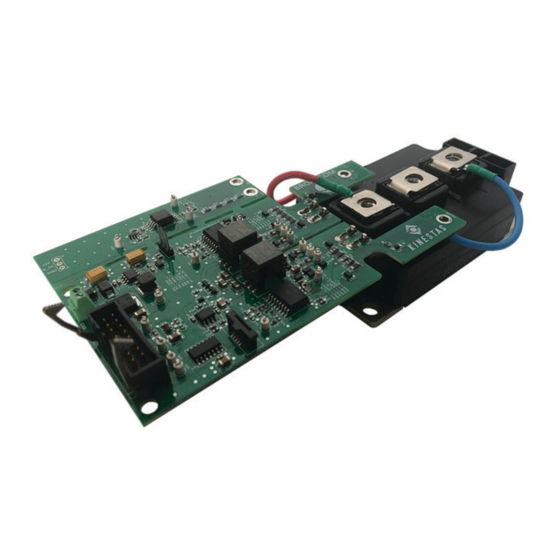
Figure 1, has been developed to support Broadcom customers during their first steps in designing power converter applications with ACPL-355JC drivers. Properties of the board are described in the following chapters of this document. Components were selected considering lead-free reflow soldering. The design was tested and verified with basic measurements described in this document, but the evaluation board is not qualified for the operation in the whole operating temperature range or lifetime. -
Page 6: Design Features
ACPL-355JC Reference Manual 62-mm SiC Module EB1200M62-355JC Evaluation Board 1.1 Design Features The EB1200M62-355JC includes the following main features: Two isolated ACPL-355JC gate drive optocouplers with the following features: – 10A peak output current – 100-kV/μs common mode rejection –... -
Page 7: Warnings
ACPL-355JC Reference Manual 62-mm SiC Module EB1200M62-355JC Evaluation Board 1.3 Warnings The board operates at high voltages. Special care must be taken to avoid injury or endanger life. While operating the board, the user must take into consideration following safety precautions: If the board is powered up, do not touch the board, especially exposed metal parts. -
Page 8: Chapter 2: System Description
EB1200M62-355JC evaluation board. Note that this table contains only key parameters. Constraints from the ACPL-355JC, ACPL-C87B, and ACPL-736J data sheets, as well as specification of other key components, must be considered when the EB1200M62-355JC is used. - Page 9 ACPL-355JC Reference Manual 62-mm SiC Module EB1200M62-355JC Evaluation Board Figure 2: Functional Block Diagram of EB1200M62-355JC Broadcom ACPL-355JC-62mmSiC-RM100...
- Page 10 ACPL-355JC Reference Manual 62-mm SiC Module EB1200M62-355JC Evaluation Board Figure 3: Disposition of the EB1200M62-355JC Functional Blocks. The Isolation Border Is Marked in Red. According to Figure 3, the marked functional blocks are as follows: 1. J1 – Auxiliary connector input 15V 2.
-
Page 11: Pin Assignment
ACPL-355JC Reference Manual 62-mm SiC Module EB1200M62-355JC Evaluation Board 2.3 Pin Assignment Pin assignment for all connectors on the EB1200M62-355JC is listed in the following sections. 2.3.1 Power Interface The J1 power supply connector is used to supply all ICs and supply gate driver voltage, and... -
Page 12: Mechanical Data
ACPL-355JC Reference Manual 62-mm SiC Module EB1200M62-355JC Evaluation Board Table 5: Pin Assignment of Jumper J3 (Power Supply Selection Jumper for Current Measurement) Label Function Direction Jumper position 1; +5V interface with current measurement. Output +5V/+3V3 Jumper common point for current measurement power supply. -
Page 13: Chapter 3: Circuit Description
ACPL-355JC Reference Manual 62-mm SiC Module EB1200M62-355JC Evaluation Board Chapter 3: Circuit Description This chapter provides in-depth insight into the EB1200M62-355JC gate driver evaluation board features. 3.1 Power Management Figure 4 shows the auxiliary power management block diagram of the EB1200M62-355JC. By default, the evaluation board is supplied from an external +15V source. - Page 14 The +15V/+5V power supply is realized with an LM2674 DC-DC switching regulator, as shown in Figure The +5V output is used to supply the low-voltage side of ACPL-355JC gate drivers and the isolated SMPS controller IC. The +5V power supply is capable of driving a 500-mA load and supplying all ICs on the board.
- Page 15 ACPL-355JC Reference Manual 62-mm SiC Module EB1200M62-355JC Evaluation Board Figure 6: Adjustable LDO +15V/(+10V ... 12V) Figure 7: Output Stage of the Isolated SMPS Broadcom ACPL-355JC-62mmSiC-RM100...
- Page 16 The EB1200M62-355JC can be connected to a current sensing module through the FPC 5-pin J4 connector. The J4 connector is provided for the external output current measurement board, which is based on Broadcom’s isolated sigma- delta modulator ACPL-736J, but different current measurement boards with an equivalent pinout can be used. Because the low-voltage side of the ACPL-736J supports a power supply of either 5V or 3.3V, the EB1200M62-355JC enables voltage...
-
Page 17: Gate Driver Circuit
ACPL-355JC Reference Manual 62-mm SiC Module EB1200M62-355JC Evaluation Board Figure 9: +5V to +5V_ISO Unregulated Isolated DC/DC Converter Figure 10: +5V/+3V3 LDO 3.2 Gate Driver Circuit This section deals with the gate driver circuitry on the EB1200M62-355JC. A description of related features and functionalities is presented in the following subsections. -
Page 18: Gate Driver Circuit: Low-Voltage Side
Figure 11: ACPL-355JC Gate Driver Circuitry With a maximum peak output current of 10A, the ACPL-355JC can drive most of the power IGBT/MOSFET switches directly without an external push-pull stage. This driver contains an LED that is electrically isolated and optically coupled to an integrated circuit on the gate driver high-voltage side with two power output stages and a CLAMP function for preventing the parasitic turn-on due to the parasitic Miller current during turn-off transient. - Page 19 While the input LED is directly polarized, and there is no fault, the turn-on command will be transferred to the high-voltage side and the ACPL-355JC V pin will go high. The ANODE pin is pulled high via resistor R3. The input signal LED_IN_P OUTP is connected to the CATHODE pin.
-
Page 20: Gate Driver Circuit: High-Voltage Side
Gint gate resistor and the internal minimum turn-on resistance of driver R . The equation for the gate resistor calculation is VOUTP given in the ACPL-355JC data sheet. Broadcom ACPL-355JC-62mmSiC-RM100... -
Page 21: Protection Features
62-mm SiC Module EB1200M62-355JC Evaluation Board The next step in choosing the right gate resistor is checking the power dissipation of the ACPL-355JC gate driver. If the power dissipation is too high, the resistance of the gate resistor should be increased. For detailed instructions on choosing the gate resistor, refer to the ACPL-355JC data sheet. - Page 22 ACPL-355JC Reference Manual 62-mm SiC Module EB1200M62-355JC Evaluation Board Figure 15: Driver Behaviors during an Over-Current Event In the current design, the threshold voltage is set to 2.5V. This means that the OC protection will react after the MOSFET drain current reaches approximately 600A for the selected MOSFET at an ambient temperature of 25°C.
-
Page 23: Uvlo
Insufficient gate voltage on the MOSFET during the turn-on phase can increase the voltage drop across the MOSFET. This results in a large power loss and MOSFET damage due to high heat dissipation. ACPL-355JC constantly monitors the output power supply. If the power supply voltage is lower than the UVLO threshold, the driver output will turn off to protect the MOSFET from low-voltage bias. - Page 24 ACPL-355JC Reference Manual 62-mm SiC Module EB1200M62-355JC Evaluation Board Figure 17: Typical Voltage Measurement Characteristic If using the proposed single-ended configuration for the end-user application, it is strongly recommended to add a capacitor parallel to resistor R29 (compare with Figure 16) in the final design to attenuate high-frequency spikes.
-
Page 25: Example Test Setup For Switching Current Measurement
ACPL-355JC Reference Manual 62-mm SiC Module EB1200M62-355JC Evaluation Board Figure 18: Detachable DC Bus Voltage Measurement Circuit Outlined in Yellow NOTE: Please take care with the polarity of the DC bus voltage connected to the measurement circuit! 3.3.2 Example Test Setup for Switching Current Measurement For measuring the switching current with a Rogowski coil, provisions can be made when designing the DC-link circuit for testing/application. -
Page 26: Connectors
ACPL-355JC Reference Manual 62-mm SiC Module EB1200M62-355JC Evaluation Board Figure 19: Test Setup Example for Measuring Module Switching Currents with a Custom Designed DC-Link 3.4 Connectors EB1200M62-355JC connectors are described in the following sections. 3.4.1 Power Connectors for the High-Voltage Side The board is supplied with the high-voltage connectors realized with the M3 screw terminals. -
Page 27: User Interface Connector
ACPL-355JC Reference Manual 62-mm SiC Module EB1200M62-355JC Evaluation Board Figure 20: +15V Power Supply Connector For reversed voltage protection, the Schottky diode is placed in series with the main power supply. 3.4.3 User Interface Connector The user interface header connector (J2) serves as an interface between the microcontroller or PWM signal source and the EB1200M62-355JC evaluation board. -
Page 28: Current Measurement Interface Connector
ACPL-355JC Reference Manual 62-mm SiC Module EB1200M62-355JC Evaluation Board 3.4.4 Current Measurement Interface Connector The EB1200M62-355JC evaluation board integrates double-buffered MCLK and MDAT input, which serves as the interface to the external current measurement board. The two signals from the ACPL-736J current sensing module are brought to the EB1200M62-355JC using an FPC connector. -
Page 29: Acpl-736J Sigma-Delta Current Sensing Module
ACPL-355JC Reference Manual 62-mm SiC Module EB1200M62-355JC Evaluation Board Figure 24: Connector J3 3.4.5 ACPL-736J Sigma-Delta Current Sensing Module The ACPL-736J sigma-delta current sensing module is a separate board that is not integrated onto the EB1200M62-355JC evaluation board. The current sensing module’s H1 connector is connected to the EB1200M62-355JC’s J4 connector using a 5-pole FPC cable. - Page 30 ACPL-355JC Reference Manual 62-mm SiC Module EB1200M62-355JC Evaluation Board Figure 26: Functional Blocks Disposition of the ACPL-736J Current Sensing Module Figure 27: Connector J3 Schematic of the ACPL-736J Current Sensing Module The ACPL-736J is a 1-bit, second-order sigma-delta modulator that converts an analog input signal into a high-speed data stream with galvanic isolation based on optical coupling technology.
-
Page 31: Installation Of The Eb1200M62-355Jc
6. With the available jumper, select the desired voltage reference for the current measurement. Available references are 5V and 3.3V. 7. Connect the user interface connector. The PWM signals as well as the ACPL-355JC output fault signals should be connected to the control board with 5V logic. -
Page 32: Evaluation Of The Eb1200M62-355Jc
Buck-boost basic features For the evaluation of the power semiconductor switching characteristics, with the EB1200M62-355JC, it is recommended to perform a double-pulse test and measure the switching transients related to the semiconductor and the ACPL-355JC gate driver circuit. Broadcom... -
Page 33: Chapter 4: Typical Switching And Over-Current Protection Characteristics
ACPL-355JC Reference Manual 62-mm SiC Module EB1200M62-355JC Evaluation Board Chapter 4: Typical Switching and Over-Current Protection Characteristics 4.1 Typical Switching Waveforms with WAB300M12BM3 Switching waveforms during hard switching of the semiconductors are measured with an oscilloscope using the standard double-pulse test procedure. The SiC MOSFET module used for testing is the Wolfspeed SiC MOSFET WAB300M12BM3. -
Page 34: Typical Switching Losses With Wab300M12Bm3
ACPL-355JC Reference Manual 62-mm SiC Module EB1200M62-355JC Evaluation Board Figure 29: Characteristic waveforms during the turn-off switching transients at different load currents. In the upper diagram, voltage waveforms are depicted with solid lines, and current waveforms are depicted with dashed lines. - Page 35 ACPL-355JC Reference Manual 62-mm SiC Module EB1200M62-355JC Evaluation Board Figure 30: Turn-on switching energy loss at 600V DC bus. In the upper diagram, voltage waveforms are depicted with solid lines, and current waveforms are depicted with dashed lines. Broadcom ACPL-355JC-62mmSiC-RM100...
-
Page 36: Typical Over-Current Protection Performance With Wab300M12Bm3
ACPL-355JC Reference Manual 62-mm SiC Module EB1200M62-355JC Evaluation Board Figure 31: Turn-off switching energy loss at 600V DC bus. In the upper diagram, voltage waveforms are depicted with solid lines, and current waveforms are depicted with dashed lines. 4.3 Typical Over-Current Protection Performance with WAB300M12BM3 The over-current protection function is demonstrated by short-circuiting the output of the power module WAB300M12BM3. -
Page 37: Typical Switching Waveforms With Ff6Mr12Km1
ACPL-355JC Reference Manual 62-mm SiC Module EB1200M62-355JC Evaluation Board Figure 32: Measurement results from over-current detection, soft short circuit at V = 600V and short circuit inductance of . In the second diagram, voltage waveforms are depicted with solid lines, and current waveforms are depicted with dashed lines. - Page 38 ACPL-355JC Reference Manual 62-mm SiC Module EB1200M62-355JC Evaluation Board Figure 33: Characteristic waveforms during the turn-on switching transients at different load currents. In the upper diagram, voltage waveforms are depicted with solid lines, and current waveforms are depicted with dashed lines.
- Page 39 ACPL-355JC Reference Manual 62-mm SiC Module EB1200M62-355JC Evaluation Board Figure 34: Characteristic waveforms during the turn-off switching transients at different load currents. In the upper diagram, voltage waveforms are depicted with solid lines, and current waveforms are depicted with dashed lines.
-
Page 40: Typical Switching Losses With Ff6Mr12Km1
ACPL-355JC Reference Manual 62-mm SiC Module EB1200M62-355JC Evaluation Board 4.5 Typical Switching Losses with FF6MR12KM1 Figure 35 shows instantaneous power during switching and the resulting turn-on switching energy loss for a DC voltage of 600V, whereas Figure 36 shows the same waveforms for the turn-off transient. - Page 41 ACPL-355JC Reference Manual 62-mm SiC Module EB1200M62-355JC Evaluation Board Figure 36: Turn-off switching energy loss at 600V DC bus. In the upper diagram, voltage waveforms are depicted with solid lines, and current waveforms are depicted with dashed lines. Broadcom ACPL-355JC-62mmSiC-RM100...
-
Page 42: Typical Over-Current Protection Performance With Ff6Mr12Km1
ACPL-355JC Reference Manual 62-mm SiC Module EB1200M62-355JC Evaluation Board 4.6 Typical Over-Current Protection Performance with FF6MR12KM1 The over-current protection function is demonstrated by short-circuiting the output of the power module FF6MR12KM1. Figure 37 shows the measurement results. Figure 37: Measurement results from over-current detection, soft short circuit at V = 600V and short circuit inductance of . -
Page 43: Appendix A: Schematics, Layout, And Bill Of Materials
ACPL-355JC Reference Manual 62-mm SiC Module EB1200M62-355JC Evaluation Board Appendix A: Schematics, Layout, and Bill of Materials This appendix provides full schematics, layout, and the bill of materials for the EB1200M62-355JC. The intention behind providing this information is to enable customers to modify, copy, and qualify the design for production, according to specific requirements. - Page 44 ACPL-355JC Reference Manual 62-mm SiC Module EB1200M62-355JC Evaluation Board Figure 39: EB1200M62-355JC – Sheet 1 – Gate Drivers and Buffer Broadcom ACPL-355JC-62mmSiC-RM100...
- Page 45 ACPL-355JC Reference Manual 62-mm SiC Module EB1200M62-355JC Evaluation Board Figure 40: EB1200M62-355JC – Sheet 2 – Power Management Broadcom ACPL-355JC-62mmSiC-RM100...
- Page 46 ACPL-355JC Reference Manual 62-mm SiC Module EB1200M62-355JC Evaluation Board Figure 41: EB1200M62-355JC – Sheet 3 – Measurements Broadcom ACPL-355JC-62mmSiC-RM100...
-
Page 47: Layout
ACPL-355JC Reference Manual 62-mm SiC Module EB1200M62-355JC Evaluation Board A.2 Layout Figure 42: EB1200M62-355JC – Assembly Drawing Broadcom ACPL-355JC-62mmSiC-RM100... - Page 48 ACPL-355JC Reference Manual 62-mm SiC Module EB1200M62-355JC Evaluation Board Figure 43: EB1200M62-355JC – Top Layer Broadcom ACPL-355JC-62mmSiC-RM100...
- Page 49 ACPL-355JC Reference Manual 62-mm SiC Module EB1200M62-355JC Evaluation Board Figure 44: EB1200M62-355JC – Signal Layer 1 Broadcom ACPL-355JC-62mmSiC-RM100...
- Page 50 ACPL-355JC Reference Manual 62-mm SiC Module EB1200M62-355JC Evaluation Board Figure 45: EB1200M62-355JC – Signal Layer 2 Broadcom ACPL-355JC-62mmSiC-RM100...
- Page 51 ACPL-355JC Reference Manual 62-mm SiC Module EB1200M62-355JC Evaluation Board Figure 46: EB1200M62-355JC – Bottom Layer Broadcom ACPL-355JC-62mmSiC-RM100...
-
Page 52: Bill Of Materials
ACPL-355JC Reference Manual 62-mm SiC Module EB1200M62-355JC Evaluation Board A.3 Bill of Materials Table 12 lists the bill of materials for the EB1200M62-355JC. Table 12: Bill of Materials for the EB1200M62-355JC Evaluation Board EB1200M62-355JC, BOM Designator MFPN C1, C11 CGA3E2X7R1H473K080AA... - Page 53 ACPL-355JC Reference Manual 62-mm SiC Module EB1200M62-355JC Evaluation Board Table 12: Bill of Materials for the EB1200M62-355JC Evaluation Board (Continued) EB1200M62-355JC, BOM Designator MFPN R13, R32 ESR03EZPJ332 ESR03EZPJ390 R23, R26 ERJ-PA3F9312V R24, R28, R30, R31 RK73G2BTTD1004C ERJ-PA3F8871V R27, R29 ESR03EZPJ154...
-
Page 54: Test Points
ACPL-355JC Reference Manual 62-mm SiC Module EB1200M62-355JC Evaluation Board A.4 Test Points Table 13 lists the available test points for the EB1200M62-355JC. Table 13: Available Test Points for the EB1200M62-355JC Evaluation Board Test Point Designator Signal VLDO PWM_H (before buffer) -
Page 55: Appendix B: Disclaimer
Appendix B: Disclaimer THIS APPLICATION NOTE CONTAINS INFORMATION THAT SHOULD SERVE ONLY AS A REFERENC FOR INITIAL EVALUATION AND IMPLEMENTATION OF THE BROADCOM INC. TECHNOLOGIES PRODUCTS. BROADCOM INC. DOES NOT TAKE RESPONSIBILITY FOR USING AND IMPLEMENTING THE PRODUCTS IN OTHER DESIGN. -
Page 56: Revision History
ACPL-355JC Reference Manual 62-mm SiC Module EB1200M62-355JC Evaluation Board Revision History ACPL-355JC-62mmSiC-RM100; Version 1.0; March 25, 2022 Initial release. Broadcom ACPL-355JC-62mmSiC-RM100... - Page 57 Broadcom reserves the right to make changes without further notice to any products or data herein to improve reliability, function, or design. Information furnished by Broadcom is believed to be accurate and reliable. However, Broadcom does not assume any liability arising out of the application or use of this information, nor the application or use of any product or circuit described herein, neither does it convey any license under its patent rights nor the rights of others.
Need help?
Do you have a question about the ACPL-355JC and is the answer not in the manual?
Questions and answers