
Related Manuals for Broadcom ACPL-352J


Summary of Contents for Broadcom ACPL-352J
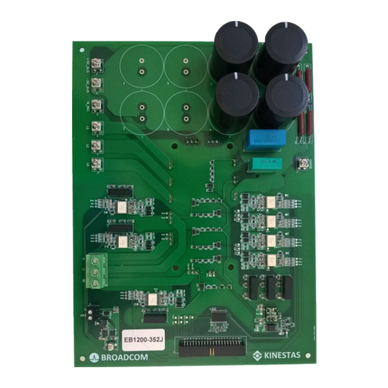
- Page 1 ACPL-352J Infineon EconoPIM™ 3 IGBT Module EB1200-352J Evaluation Board Reference Manual Version 1.0 Broadcom ACPL-352J-EB1200-RM100 October 3, 2019...
- Page 2 The term “Broadcom” refers to Broadcom Inc. and/or its subsidiaries. For more information, please visit www.broadcom.com. Broadcom reserves the right to make changes without further notice to any products or data herein to improve reliability, function, or design. Information furnished by Broadcom is believed to be accurate and reliable. However, Broadcom does not assume any liability arising out of the application or use of this information, nor the application or use of any product or circuit described herein, neither does it convey any license under its patent rights nor the rights of others.
-
Page 3: Table Of Contents
ACPL-352J Reference Manual Infineon EconoPIM™ 3 IGBT Module EB1200-352J Evaluation Board Table of Contents Chapter 1: About This Document ...................... 5 1.1 Scope and Purpose..............................5 1.2 Warnings..................................5 Chapter 2: Introduction ........................7 2.1 Design Features ................................8 2.2 Target Applications..............................8 Chapter 3: System Description ......................9 3.1 Key Specifications ..............................9... - Page 4 ACPL-352J Reference Manual Infineon EconoPIM™ 3 IGBT Module EB1200-352J Evaluation Board Revision History ..........................41 Version 1.0, October 3, 2019 ............................41 Broadcom ACPL-352J-EB1200-RM100...
-
Page 5: Chapter 1: About This Document
(PIM) FP75R12KT4 and FP50R1200KT4G, but other PIMs with the same pin layout can be used as well. The integrated DC bus feature enables customers to evaluate the ACPL-352J isolated gate driver in conditions similar to actual applications, such as an industrial inverter. - Page 6 ACPL-352J Reference Manual Infineon EconoPIM™ 3 IGBT Module EB1200-352J Evaluation Board WARNING! Due to the technical requirements, high voltage components are used, and some of them could contain dangerous substances. Because the failure of such components can harm the user and even endanger the user's life, it is necessary to take all necessary precautions and safety measures prior to the evaluation of the EB1200-352J.
-
Page 7: Chapter 2: Introduction
The design is tested, as described in this document, at the temperature of 25°C, but it is not qualified regarding operation in the entire operating ambient temperature range of ACPL-352J, or its lifetime. The board is subjected to functional testing only. -
Page 8: Design Features
Infineon EconoPIM™ 3 IGBT Module EB1200-352J Evaluation Board 2.1 Design Features The EB1200-352J includes the following main features: Seven isolated ACPL-352J gate drivers with the following features: – Dual output drive to control turn-on and turn-of time independently – Overcurrent (OC) protection with configurable soft shutdown function –... -
Page 9: Chapter 3: System Description
EB1200-352J. Note that Table 1 contains only key parameters. Constraints from ACPL-352J data sheet as well as specifications of other key components must be considered when the EB1200-352J is used. Table 1: Absolute Maximum Ratings... - Page 10 ACPL-352J Reference Manual Infineon EconoPIM™ 3 IGBT Module EB1200-352J Evaluation Board Figure 2: EB1200-352J Functional Block Diagram Broadcom ACPL-352J-EB1200-RM100...
- Page 11 ACPL-352J Reference Manual Infineon EconoPIM™ 3 IGBT Module EB1200-352J Evaluation Board Figure 3: Functional Block Disposition of the EB1200-352J Broadcom ACPL-352J-EB1200-RM100...
-
Page 12: Pin Assignments
ACPL-352J Reference Manual Infineon EconoPIM™ 3 IGBT Module EB1200-352J Evaluation Board 3.3 Pin Assignments This section describes the pin assignments of signal and power interface on the EB1200-352J. Part numbers and mechanical details of each connector can be found using manufacturer part numbers provided in Section A.3,... -
Page 13: Power Interface
ACPL-352J Reference Manual Infineon EconoPIM™ 3 IGBT Module EB1200-352J Evaluation Board Table 2: Pinout of Connector J1 (Continued) Label Function Direction GFAULT.W GFAULT signal for high-side power switch in phase W Output GFAULT.Z GFAULT signal for low-side power switch in phase B Output GFAULT.B... -
Page 14: Chapter 4: Circuit Description
5a. The +5V output of this power supply is used to supply the ACPL-352J gate drivers and the ACPL-C87A voltage sensor low-voltage side. An isolated 5V/5V voltage regulator, R1SX-0505-R, provides an isolated 5V for the ACPL-C87A high-voltage side, as shown in Figure 5b. -
Page 15: Gate Driver Circuit
Figure 5: (a) 24V/5V Power Supply of the EB1200-352J Board, and (b) the Isolated 5V/5V Power Supply Figure 6: 24V/+15V/–15V Isolated Gate Driver High-Voltage Side Power Supply 4.2 Gate Driver Circuit The used optocoupler-based IGBT gate drivers, ACPL-352J, feature fast signal propagation, desaturation detection, soft shutdown protection, active clamping, and fault feedback. Figure 7 shows the both the low-voltage and high-voltage side gate driver circuit. -
Page 16: Gate Driver Circuit: High-Voltage Side
VDD2, LED current (IF) and overcurrent (OC) conditions. For the details related to the logic truth table of these outputs, refer to the ACPL-352J data sheet. The driver provides an ideal solution combining local overcurrent detection (OC), soft shutdown (SS) with high-speed current output and highp-voltage optical isolation. - Page 17 OC(BLANKING) during an OC fault condition. Figure 11: Circuit Behaviors during an Overcurrent Condition. The diagram is the same as in the ACPL-352J data sheet. The OC terminal monitors the voltage between the collector and the emitter (V ) of the IGBT. When this voltage exceeds 9V, the output voltages (VOUTP and VOUTN) go to high impedance state and the SS pulls down the VGATE at a slow rate adjustable using the resistor.
-
Page 18: Gate Resistor Consideration
4A. The next step in choosing the correct gate resistor is to check the power dissipation of the ACPL-352J gate driver. If the power dissipation is too high, the resistance of the gate resistor should be increased. For detailed instructions on choosing the gate resistor, refer to the ACPL-352J data sheet. -
Page 19: Dc Bus And Discharge Resistors
VOUTP and with 4.7Ω for negative gating connected to VOUTN as a default assembled variant. In addition, evaluation board is designed to enable Broadcom customers to evaluate switching characteristics of the semiconductors by changing or combining turn-on/turn-off resistors (as described in Section 4.2.2, Gate Driver Circuit: High-Voltage... -
Page 20: Igbt Current Measurement
ACPL-352J Reference Manual Infineon EconoPIM™ 3 IGBT Module EB1200-352J Evaluation Board 4.4 IGBT Current Measurement To enable users to obtain a semiconductor current waveform during switching instances, the board is designed with two dedicated holes mechanically positioned to cover the traces connecting the low-side emitters and the negative potential of... - Page 21 ACPL-352J Reference Manual Infineon EconoPIM™ 3 IGBT Module EB1200-352J Evaluation Board Figure 15: EB1200-352J Isolated Temperature Measurement Circuit Figure 16: Typical Temperature Measurement Characteristic Broadcom ACPL-352J-EB1200-RM100...
-
Page 22: Chapter 5: Setup
2. Ground the board. Connect the –DC_BUS terminal to earth potential. 3. Connect the signal connector. The PWM signals as well as the ACPL-352J output fault signals can be connected to any control board with 5V/3.3V logic. - Page 23 ACPL-352J Reference Manual Infineon EconoPIM™ 3 IGBT Module EB1200-352J Evaluation Board To evaluate semiconductor switching characteristics with the EB1200-352J, perform a double pulse test, and measure the transients related to the semiconductor and the ACPL-352J driver circuit. Broadcom ACPL-352J-EB1200-RM100...
-
Page 24: Chapter 6: Typical Switching And Desat Protection Characteristics
ACPL-352J Reference Manual Infineon EconoPIM™ 3 IGBT Module EB1200-352J Evaluation Board Chapter 6: Typical Switching and DESAT Protection Characteristics 6.1 Typical Switching Losses Because the EB1200-352J has integrated a DC bus capacitor bank, the worst-case commutation inductance (measured for the switch with the longest path to the DC bus capacitors) is a constant 67 nH and does not vary from the setup used to characterize switching characteristic. -
Page 25: Typical Switching Waveforms
ACPL-352J Reference Manual Infineon EconoPIM™ 3 IGBT Module EB1200-352J Evaluation Board 6.2 Typical Switching Waveforms Switching waveforms during hard switching of the semiconductors are measured with an oscilloscope using the standard double-pulse test procedure. Figure 18 shows the turn-on switching transient, while in... -
Page 26: Typical Gfault Performance
ACPL-352J Reference Manual Infineon EconoPIM™ 3 IGBT Module EB1200-352J Evaluation Board Figure 20: Measurement Results from DESAT Detection, Direct Short Circuit at V = 600V, CH1 (Yellow) V , CH3 (Blue) V CH4 (Green) V , F6 (Red) I 6.4 Typical GFAULT Performance Typical GFAULT detection in condition when the gate voltage is below the GFAULT thresholds is shown in Figure 21 in cases a) IGBT turn-on and b) IGBT turn-off. -
Page 27: Appendix A: Schematics, Layout, And Bom
ACPL-352J Reference Manual Infineon EconoPIM™ 3 IGBT Module EB1200-352J Evaluation Board Appendix A: Schematics, Layout, and BOM This appendix includes full schematics, layout, and bill of materials of the EB1200-352J. This information helps customers to modify, copy, and qualify the design for production, according to specific requirements. -
Page 28: Schematics
ACPL-352J Reference Manual Infineon EconoPIM™ 3 IGBT Module EB1200-352J Evaluation Board A.1 Schematics Figure 22: EB1200-352J Top-Level Sheet Broadcom ACPL-352J-EB1200-RM100... - Page 29 ACPL-352J Reference Manual Infineon EconoPIM™ 3 IGBT Module EB1200-352J Evaluation Board Figure 23: EB1200-352J, Sheet 1, Connector Broadcom ACPL-352J-EB1200-RM100...
- Page 30 ACPL-352J Reference Manual Infineon EconoPIM™ 3 IGBT Module EB1200-352J Evaluation Board Figure 24: EB1200-352J, Sheet 2, DC Bus Broadcom ACPL-352J-EB1200-RM100...
- Page 31 ACPL-352J Reference Manual Infineon EconoPIM™ 3 IGBT Module EB1200-352J Evaluation Board Figure 25: EB1200-352J, Sheet 3, Drivers Broadcom ACPL-352J-EB1200-RM100...
- Page 32 ACPL-352J Reference Manual Infineon EconoPIM™ 3 IGBT Module EB1200-352J Evaluation Board Figure 26: EB1200-352J, Sheet 4, IGBT Module Broadcom ACPL-352J-EB1200-RM100...
- Page 33 ACPL-352J Reference Manual Infineon EconoPIM™ 3 IGBT Module EB1200-352J Evaluation Board Figure 27: EB1200-352J, Sheet 5, Power Management Broadcom ACPL-352J-EB1200-RM100...
-
Page 34: Layout
ACPL-352J Reference Manual Infineon EconoPIM™ 3 IGBT Module EB1200-352J Evaluation Board A.2 Layout Figure 28: EB1200-352J, Assembly Drawing Broadcom ACPL-352J-EB1200-RM100... - Page 35 ACPL-352J Reference Manual Infineon EconoPIM™ 3 IGBT Module EB1200-352J Evaluation Board Figure 29: EB1200-352J, Top Layer Broadcom ACPL-352J-EB1200-RM100...
- Page 36 ACPL-352J Reference Manual Infineon EconoPIM™ 3 IGBT Module EB1200-352J Evaluation Board Figure 30: EB1200-352J, Signal Layer 1 Broadcom ACPL-352J-EB1200-RM100...
- Page 37 ACPL-352J Reference Manual Infineon EconoPIM™ 3 IGBT Module EB1200-352J Evaluation Board Figure 31: EB1200-352J, Signal Layer 2 Broadcom ACPL-352J-EB1200-RM100...
- Page 38 ACPL-352J Reference Manual Infineon EconoPIM™ 3 IGBT Module EB1200-352J Evaluation Board Figure 32: EB1200-352J, Bottom Layer Broadcom ACPL-352J-EB1200-RM100...
-
Page 39: Bom
ACPL-352J Reference Manual Infineon EconoPIM™ 3 IGBT Module EB1200-352J Evaluation Board A.3 BOM Table 5 shows the bill of materials for the EB1200-352J. Table 5: Bill of Materials for the EB1200-352J Designator Manufacturer Part Number C1, C72 VJ1206Y103JXAMC GMK316BJ106KL-T C3, C16, C24, C32, C40, C48, C56, C64... -
Page 40: Disclaimer
A.4 Disclaimer THIS APPLICATION NOTE CONTAINS INFORMATION THAT SHOULD SERVE ONLY AS A FIRST STEP FOR EVALUATION AND IMPLEMENTATION OF THE BROADCOM INC. TECHNOLOGIES. KINESTAS DOO DOES NOT TAKE RESPONSIBILITY FOR USING AND IMPLEMENTING BROADCOM TECHNOLOGIES IN OTHER DESIGNS. Broadcom... - Page 41 ACPL-352J Reference Manual Infineon EconoPIM™ 3 IGBT Module EB1200-352J Evaluation Board Revision History Version 1.0, October 3, 2019 Initial release of the document. Broadcom ACPL-352J-EB1200-RM100...
Need help?
Do you have a question about the ACPL-352J and is the answer not in the manual?
Questions and answers