
Related Manuals for Broadcom AEDR-9820


Summary of Contents for Broadcom AEDR-9820
- Page 1 AEDR-9820 & 9830 Evaluation Board User Guide User Guide Version 1.0 Footer Document_Number April 9, 2020...
- Page 2 The term “Broadcom” refers to Broadcom Limited and/or its subsidiaries. For more information, please visit www.broadcom.com. Broadcom reserves the right to make changes without further notice to any products or data herein to improve reliability, function, or design. Information furnished by Broadcom is believed to be accurate and reliable. However, Broadcom does not assume any liability arising out of the application or use of this information, nor the application or use of any product or circuit described herein, neither does it convey any license under its patent rights nor the rights of others.
-
Page 3: Table Of Contents
AEDR-9820 & 9830 User Guide Evaluation Board User Guide Table of Contents Top and Bottom Views ............................4 Select Options ..............................6 2.1 Selection Table ..............................6 Board Schematic & Pin Assignment ......................... 7 3.1 Connector Assignment ....................Error! Bookmark not defined. -
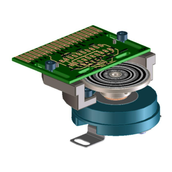
Page 4: Top And Bottom Views
Top and Bottom Views Figure 1 Bottom Side of the PCB Mounting slot Mounting hole Figure 2 Top Side of the PCB (Left 318 LPI & Right 225 LPI) Code wheel OD alignment guide lines NOTE Please remove the protective kapton tape covering the encoder ASIC before use. - Page 5 The silk screen printed guide line on the PCB is to help in providing visual alignment of the code wheel edge (outer diameter) for each of the different Rop (CPR) track. A sample diagram showing the position when encoder is aligned to 625 CPR track is as shown in Figure 3 below.
-
Page 6: Select Options
Analog (500mVpp) Analog 200 kHz High Analog 1Vpp Ungated Digital High / Low Open Analog 1Vpp Analog Table 2 Selection Table for 225 LPI AEDR-9820 Variant INDEX Interpolation CPR @ROP CPR @ROP 11 SEL1 SEL 2 Index Max output Factor 4.6 mm... -
Page 7: Board Schematic & Pin Assignment
3.0 Board Schematic & Pin Assignment Figure 5 Evaluation Board Schematic... -
Page 8: Connector Assignment
3.1 Connector Assignment Table 3 : Connector 1 Pin Assignment Connector 1 (Top Side) Label INDEX_P/I+ INDEX_P/I- VSSA/AGND VDDA/VCC CH_A/A+ CH_AB/A- VSSD/DGND CH_B/B+ CH_BB/B- The finger design of Connector 1 is match to the following connectors: 1. EDAC, CONN EDGE DUAL FMALE 36POS 0.100, P/N# 395-036-520-202 or, 2. - Page 9 Connector 1 (Top Side) Label State SEL1 AGND OPEN SEL2- AGND OPEN INDEX_SEL AGND OPEN NOTE Please refer to Table 1 (AEDR-9830 318 LPI) or Table 2 (AEDR-9820 225 LPI) for the various selection options available by changing the respective jumper position.
-
Page 10: Code Wheel Drawing
For AEDR-9830 evaluation board sample, the matching code wheel sample drawing is as shown in Figure 4 below. Figure 6 318 LPI 4-track (CPR) code wheel drawing For AEDR-9820 evaluation board sample, the matching code wheel sample drawing is as shown in Figure 5 below. Figure 7 225 LPI 4-track (CPR) code wheel drawing... - Page 12 Mouser Electronics Authorized Distributor Click to View Pricing, Inventory, Delivery & Lifecycle Information: Broadcom Limited HEDS-9820EVB HEDS-9830EVB...
Need help?
Do you have a question about the AEDR-9820 and is the answer not in the manual?
Questions and answers