
Subscribe to Our Youtube Channel
Related Manuals for Broadcom ACPL-352J


Summary of Contents for Broadcom ACPL-352J
- Page 1 ACPL-352J Vincotech H6.5 3-Level IGBT flowPACK Module Evaluation Board Reference Manual Version 1.0 Broadcom Confidential ACPL-352J-Ref-RM100 April 13, 2018...
- Page 2 The term “Broadcom” refers to Broadcom Inc. and/or its subsidiaries. For more information, please visit www.broadcom.com. Broadcom reserves the right to make changes without further notice to any products or data herein to improve reliability, function, or design. Information furnished by Broadcom is believed to be accurate and reliable. However, Broadcom does not assume any liability arising out of the application or use of this information, nor the application or use of any product or circuit described herein, neither does it convey any license under its patent rights nor the rights of others.
-
Page 3: Table Of Contents
ACPL-352J Reference Manual Vincotech H6.5 3-Level IGBT flowPACK Module Evaluation Board Table of Contents Chapter 1: Introduction ........................4 1.1 3-Level Topology...............................4 Chapter 2: Description of H6.5 Evaluation Board ................5 2.1 Board Description ..............................5 2.2 Basic Operation.................................8 2.3 Gate Drive Design ..............................9 Chapter 3: Test Circuit and Result .................... -
Page 4: Chapter 1: Introduction
ACPL-352J Reference Manual Vincotech H6.5 3-Level IGBT flowPACK Module Evaluation Board Chapter 1: Introduction 1.1 3-Level Topology 3-Level topology has two main advantages over conventional 2-Level topology, namely higher efficiency and reduction in filtering effort. 2-Level topology requires a large output filter and regenerates energy back to the DC bulk capacitor during freewheeling. -
Page 5: Chapter 2: Description Of H6.5 Evaluation Board
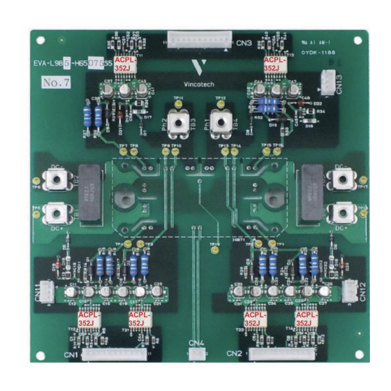
ACPL-352J Reference Manual Vincotech H6.5 3-Level IGBT flowPACK Module Evaluation Board Chapter 2: Description of H6.5 Evaluation Board 2.1 Board Description Figure 3: Evaluation Board for flowPACK 1 H6.5 Module ACPL- ACPL- 352J 352J ACPL- ACPL- ACPL- ACPL- 352J 352J... - Page 6 Figure 5: Schematic of 10-FY07HVA050S5 and flowPACK1 Module Six ACPL-352J gate drive optocouplers are used to drive the six IGBTs. The ACPL-352J is industry's highest output current, 5A smart gate drive optocoupler. The high peak output current, together with wide operating voltage make it ideal for driving the IGBT directly.
- Page 7 ACPL-352J Reference Manual Vincotech H6.5 3-Level IGBT flowPACK Module Evaluation Board Figure 6: Block Diagram of ACPL-352J and SO-16 Package This reference design will describe the basic operation of the evaluation board and the gate drive design. Other information like the layouts and BOM of the H6.5 evaluation board can be found in Vincotech reference design website: https://www.vincotech.com/support-and-documents/evaluation-board-reference-design.html...
-
Page 8: Basic Operation
ACPL-352J Reference Manual Vincotech H6.5 3-Level IGBT flowPACK Module Evaluation Board 2.2 Basic Operation Figure 7: Basic Circuit of the Logical Control Figure 7 shows the circuit to control the logical switching sequence of the six IGBTs. Figure 8 shows the simulated waveforms. -
Page 9: Gate Drive Design
CMR performance of more than100 kV/µs. The OC pin of ACPL-352J is connected to the collector of IGBT T12 via a high voltage blocking diode, D5 and resistor R13. - Page 10 ACPL-352J Reference Manual Vincotech H6.5 3-Level IGBT flowPACK Module Evaluation Board During overcurrent fault condition, the IGBT is soft shut down through the SS pin and the rate of shut down can be adjusted by R14. The gate resistors (R15/R16) serve to limit gate current and indirectly control the IGBT switching times. Diode, D1 is used together with the CLAMP function to shunt parasitic IGBT Miller current during the off cycle.
- Page 11 ACPL-352J Reference Manual Vincotech H6.5 3-Level IGBT flowPACK Module Evaluation Board Figure 10: Schematic of the Evaluation Board Broadcom Confidential ACPL-352J-Ref-RM100...
-
Page 12: Chapter 3: Test Circuit And Result
ACPL-352J Reference Manual Vincotech H6.5 3-Level IGBT flowPACK Module Evaluation Board Chapter 3: Test Circuit and Result 3.1 Test Setup and Waveform The test items and corresponding test pins are shown in Figure Figure 11: Test Items and Test Pins... - Page 13 ACPL-352J Reference Manual Vincotech H6.5 3-Level IGBT flowPACK Module Evaluation Board Figure 12: Waveforms of 3-Level Operation Broadcom Confidential ACPL-352J-Ref-RM100...
-
Page 14: Appendix A: References
ACPL-352J Reference Manual Vincotech H6.5 3-Level IGBT flowPACK Module Evaluation Board Appendix A: References 1. “ACPL-352J 5.0 Amp Output Current IGBT and SiC/GaN MOSFET Gate Drive Optocoupler with Integrated Over Current Sensing, FAULT, GATE,and UVLO Status Feedback,” Broadcom Inc., pub-005603. https://docs.broadcom.com/docs/pub-005817 2.
Need help?
Do you have a question about the ACPL-352J and is the answer not in the manual?
Questions and answers