
Related Manuals for AXIOMTEK ProX-1675


Summary of Contents for AXIOMTEK ProX-1675
- Page 1 USER’S MANUAL ProX-1675 For Socket 370 Embedded Board With VGA / Sound / LAN Prox-1675 M6...
- Page 2 Copyright Notice ProX-1675 Socket 370 Embedded Board With VGA / SOUND / LAN OPERATION MANUAL COPYRIGHT NOTICE This operation manual is meant to assist both Embedded Computer manu- facturers and end-users in installing and setting up the system. The infor- mation contained in this document is subject to change without any prior notice.
-
Page 3: Table Of Contents
Contents TABLE OF CONTENTS CHAPTER 1 INTRODUCTION About This Manual ............System Specifications ........... Safety Precautions ............CHAPTER 2 HARDWARE CONFIGURATION Jumper & Connector Quick Reference Table ....Component Locations ........... How to Set the Jumpers ..........COM Port Connector ............ RS232/422/485 (COM2) Selection ....... - Page 4 Contents 2-30 LAN Connector ............2-27 2-31 Power Connector …………………………………….. 2-27 2-32 Sound Connector ……………………………………... 2-28 2-33 CD Audio-In Connector ……………………………… 2-28 2-34 PCI or Riser Card Selection ………………………….. 2-29 2-35 Clear CMOS Selection ……………………………….. 2-29 2-36 Memory Installation ............2-30 2-37 CPU Type Selection ………………………………...
- Page 5 Contents PC Health Status ……………………………………… 5-25 5-10 Frequency/Voltage Control ………………………… 5-26 5-11 Load Fail-Safe Defaults ..........5-27 5-12 Load Optimized Defaults ..........5-27 5-13 Password Setting ............5-28 5-14 Save & Exit Setup ............5-29 5-15 Exit Without Saving ............5-30 APPENDIX A ADAPTER CARD W-Sound Adapter Card …............
-
Page 6: Chapter 1 Introduction
CHAPTER INTRODUCTION This chapter gives you the information for Prox-1675. It also outlines the System specifications. Section includes: About This Manual System Specifications Safety precautions Experienced users can skip to chapter 2 on page 2-1 for a Quick Start. Page:1-1... -
Page 7: About This Manual
Chapter 1 Introduction 1-1. ABOUT THIS MANUAL Thank you for purchasing our Prox-1675 Socket 370 Embedded Board enhanced with VGA/Sound/LAN, is fully PC / AT compatible. The Prox- 1675 provides faster processing speed, greater expandability and can handle more tasks than before. This manual is designed to assist you how to install and set up the system. -
Page 8: System Specifications
Dallas DS 12887 Real Time Clock. BIOS : Award Flash BIOS for plug & play function. Easy update 256KB flash EEPROM. Support Green Function. Support S/IO Setup. KEYBOARD CONNECTOR : 5-pin AT keyboard connector with mini DIN cable. ′ Page: 1-3 Prox-1675 USER S MANUAL... - Page 9 Support up to two Floppy Disk Drives, 3.5" and 5.25" (360K / 720K / 1.2M / 1.44M / 2.88M / LS-120). DISK-ON-CHIPS SOCKET : A 32-pin SSD socket on board, supports up to 144MB Disk-on-chips. ′ Page: 1-4 Prox-1675 USER S MANUAL...
- Page 10 Software supported by BIOS setup. Hardware supported by switch control. HARDWARE MONITORING FUNCTION : Monitor CPU Voltage, CPU temperature, and Cooling Fan. LED INDICATOR : System power. Hard Disk access. LAN LED indicators. ′ Page: 1-5 Prox-1675 USER S MANUAL...
- Page 11 DC Ampere: 7A. DC Voltage: +12V, minimum +11.4V, maximum +12.6V. DC Ampere: 0.2A. DC Voltage: +3.3V, minimum +3.135V, maximum +3.465V. DC Ampere: 3A. BOARD DIMENSION : 146mm x 203mm BOARD NET WEIGHT : 0.3 Kilograms. ′ Page: 1-6 Prox-1675 USER S MANUAL...
-
Page 12: Safety Precautions
3. Disconnect power when you change any hardware devices. For instance, when you connect a jumper or install any cards, a surge of power may damage the electronic components or the whole system. ′ Page: 1-7 Prox-1675 USER S MANUAL... - Page 13 Chapter 1 Introduction ′ Page: 1-8 Prox-1675 USER S MANUAL...
-
Page 14: Jumper & Connector Quick Reference Table
HARDWARE CHAPTER CONFIGURATION ** QUICK START ** Helpful information describes the jumper & connector settings, and component locations. This section includes: Jumper & Connector Quick Reference Table Component Locations Configuration and Jumper settings Connector‘s Pin Assignments Page 2-1... - Page 15 PCI or Riser Card Selection …………………….……... J5, J2, J3 Clear CMOS Selection ………………………….……... Memory Installation ..........…….. DIMM1 CPU Type Selection …………………………….…….. J7, J8, J9 Power LED Connector ………………………………… JP13 Reserved pin …………………………………………… FAN1, WOL1 …………………………………………... WOL2 ’ Page: 2-2 Prox-1675 USER S MANUAL...
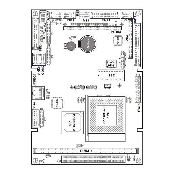
- Page 16 Chapter 2 Hardware Configuration 2-2. COMPONENT LOCATIONS USB1 PRT1 WOL2 WOL1 PC104 LVDS2 LVDS1 FAN1 DIMM 1 Prox-1675 Connector, Jumper and Component locations ’ Page: 2-3 Prox-1675 USER S MANUAL...
-
Page 17: How To Set The Jumpers
PIN1 & PIN2 to create one setting and shorting. You can either connect PIN2 & PIN3 to create another setting. The same jumper diagrams are applied all through this manual. The figure below shows what the manual diagram looks like and what they represent. ’ Page: 2-4 Prox-1675 USER S MANUAL... - Page 18 Chapter 2 Hardware Configuration JUMPER DIAGRAMS JUMPER SETTINGS ’ Page: 2-5 Prox-1675 USER S MANUAL...
-
Page 19: Com Port Connector
The COM1 Connector assignments are as follows : ASSIGNMENT COM1 RI / +5V / +12V selectable COM2 : COM2 Connector The COM2 Connector assignments are as follows : ASSIGNMENT RS-232 RS-422 RS-485 COM2 RTS- RTS+ CTS+ RI/+5V/+12 CTS- ’ Page: 2-6 Prox-1675 USER S MANUAL... - Page 20 COM4 RI / +5V / +12V selectable All COM port’s pin 9 is selectable for RI, +5V or +12V. For more information, please refer to our “RI Voltage Selection” & “COM RI Selection” ’ Page: 2-7 Prox-1675 USER S MANUAL...
-
Page 21: Rs232/422/485 (Com2) Selection
JUMPER SETTING JUMPER FUNCTION (pin closed) ILLUSTRATION Open RS-232 1-2, 5-6, 7-8, 9-10 RS-422 11-12, 13-14, 15-16 17-18, 19-20 1-3, 4-6, 7-8, 9-10 RS-485 11-12, 13-14, 15-16 17-18, 19-20 *** Manufactory default --- RS-232. ’ Page: 2-8 Prox-1675 USER S MANUAL... -
Page 22: Com Ri & Voltage Selection
COM2 Voltage Open COM3 Voltage Open COM4 Voltage Open ***Manufacturing Default – RI. (All jumpers are closed). For Voltage Selection, user may select +5V / +12V, please refer to our “RI Voltage Selection”. ’ Page: 2-9 Prox-1675 USER S MANUAL... -
Page 23: Ri Voltage Selection
J1 (7,9,11) : COM3 Voltage Selection J1 (8,10,12) : COM4 Voltage Selection The selections are as follows: COM PORT VOLTAGE JUMPER JUMPER SELECTION SETTINGS ILLUSTRATION COM1 +12V COM2 +12V COM3 +12V 9-11 8-10 COM4 +12V 10-12 ’ Page: 2-10 Prox-1675 USER S MANUAL... - Page 24 Chapter 2 Hardware Configuration 2-8. SOLID-STATE DISK SOCKET SSD: 32-pin Disk-on-chip Socket The pin assignments are as follows: ASSIGNMENT ASSIGNMENT SA12 SA10 SA11 ’ Page: 2-11 Prox-1675 USER S MANUAL...
-
Page 25: Ssd Memory Mapping Selection
ROM SSD can be install as one of user’s hard disk drive. The SSD Memory Mapping Selections are as follows: Jumper Settings SSD Memory Map Jumper (pins closed) Illustration CC000h-CDFFFh D0000h-D1FFFh D4000h-D5FFFh D8000h-D9FFFh DC000h-DDFFFh *** Manufactory default --- CC000h-CDFFFh ’ Page: 2-12 Prox-1675 USER S MANUAL... -
Page 26: Ps/2 Mouse Connector
KB1 : PC/AT Keyboard Connector The jumper settings are as follows: ASSIGNMENT KBCLK KBDATA KBVCC 2-11. PS/2 MOUSE CONNECTOR MS1 : PS/2 Mouse Connector The pin assignments are as follows : ASSIGNMENT MSCLK MSDATA MSVCC ’ Page: 2-13 Prox-1675 USER S MANUAL... -
Page 27: Reset Connector
GROUND RESET 2-13. HARD DISK DRIVE LED CONNECTOR JP2 (22,24,26,28) : Hard Disk Drive LED Connector The pin assignments are as follows : ASSIGNMENT HDD Active Signal HDD Active Signal HDD Active Signal ’ Page: 2-14 Prox-1675 USER S MANUAL... -
Page 28: External Speaker Connector
Speaker Signal (Buz) Speaker Signal (Buz) Speaker Signal (Buz) 2-15. LAN LED INDICATOR JP2 (15-20): LAN LED Indicator The pin assignments are as follows : ASSIGNMENT PULL HI LED2-10Mbps PULL HI LED1-100Mbps PULL HI LED0-Link/Active ’ Page: 2-15 Prox-1675 USER S MANUAL... -
Page 29: Power Button
2-16. POWER BUTTON JP2 (8,10): Power Botton The pin assignments are as follows: ASSIGNMENT PWR_BTN GROUND 2-17. IRDA CONNECTOR JP2 (1,3,5,7,9): IrDA (SIR) Connector The pin assignments are as follows: ASSIGNMENT IRRX IRTX ’ Page: 2-16 Prox-1675 USER S MANUAL... -
Page 30: Green Function Connector
JP2 (13,14): Green Function Connector The pin assignments are as follows: ASSIGNMENT EXTSMI- 2-19. PANELLINK & LVDS SELECTION JP12: PanelLink™ & LVDS Selection The selections are as follows: JUMPER JUMPER SETTING SELECTION ILLUSTRATION (pin closed) PanelLink™ LVDS ’ Page: 2-17 Prox-1675 USER S MANUAL... -
Page 31: Vga Connector
Chapter 2 Hardware Configuration 2-20. VGA CONNECTOR VGA : VGA Connector The pin assignments are as follows: ASSIGNMENT GREEN BLUE PULL HI HSYNC VSYNC PULL HI ’ Page: 2-18 Prox-1675 USER S MANUAL... -
Page 32: Panellink (Dfp) Connector
15-pin DDC2B compliant VGA connector (if present). The pin assignments are as follows : ASSIGNMENT ASSIGNMENT TX1+ TX2+ TX1- TX2- TXC+ TX0+ TXC- TX0- Panel detect ’ Page: 2-19 Prox-1675 USER S MANUAL... -
Page 33: Lvds Connector
The pin assignments are as follows : ASSIGNMEN ASSIGNMENT LVDS2 TXU1+ TXU1- TXU3+ TXU3- TXU0+ TXU0- TXCLKU+ TXCLKU- TXU2+ TXU2- PANELDET 24bit and below panel used LVDS1, 36/48bit panel used LVDS1 and LVDS2. ’ Page: 2-20 Prox-1675 USER S MANUAL... -
Page 34: Lvds Panel Voltage Selection
3.3V VCC 2-24. UNIVERSAL SERIAL BUS CONNECTOR USB: Universal Serial Bus Connector USB connector of this board can support two USB ports. The pin assignments are as follows: ASSIGNMENT USB1 USBP∅− USBP∅+ USBP1− USBP1+ ’ Page: 2-21 Prox-1675 USER S MANUAL... -
Page 35: Floppy Disk Drive Connector
34-pin flat cable to attach the FDD on the board, the other side attaches to two FDDs. The pin assignments are as follows : ASSIGNMENT ASSIGNMENT DRVDEN0 DRVDEN1 INDEX MTR0 DRV1 DRV0 MTR1 STEP WDATA WGATE TRK0 WRPRT RDATA DSKCHG ’ Page: 2-22 Prox-1675 USER S MANUAL... -
Page 36: Hard Disk Drive Connector
ASSIGNMENT IDERST PDD7 PDD8 PDD6 PDD9 PDD5 PDD10 PDD4 PDD11 PDD3 PDD12 PDD2 PDD13 PDD1 PDD14 PDD0 PDD15 DDREQA -DIOWA -DIORA HDRDYA PULL LOW -DDACKA IRQ14 PDA1 PD_80P PDA0 PDA2 -PDCS1 -PDCS3 HDLED1 ’ Page: 2-23 Prox-1675 USER S MANUAL... - Page 37 ASSIGNMENT IDERST SDD7 SDD8 SDD6 SDD9 SDD5 SDD10 SDD4 SDD11 SDD3 SDD12 SDD2 SDD13 SDD1 SDD14 SDD0 SDD15 DDREQB -DIOWB -DIORB HDRDYB PULL LOW -DDACKB IRQ15 SDA1 SD_80P SDA0 SDA2 -SDCS1 -SDCS3 HDLED2 ’ Page: 2-24 Prox-1675 USER S MANUAL...
-
Page 38: Printer Connector
As to link the Printer to the card, you need a cable to connect both DB25 connector and parallel port. The pin assignments are as follows : ASSIGNMENT ASSIGNMENT AUTFE ERROR INIT SLCTIN BUSY SLCT ’ Page: 2-25 Prox-1675 USER S MANUAL... -
Page 39: Cpu Fan Connector
FAN2 IN +12V FAN2 2-29. RESET/NMI/CLEAR WATCHDOG SELECTION JP6 : Reset/NMI/Clear Watchdog Selection The selections are as follows: FUNCTION JUMPER SETTING JUMPER (pin closed) ILLUSTRATION RESET CLEAR WATCHDOG ***Manufacturing Default is set as Reset. ’ Page: 2-26 Prox-1675 USER S MANUAL... -
Page 40: Lan Connector
ISOLATED GND 2-31. POWER CONNECTOR PWR : Power Connector The pin assignments are as follows : ASSIGNMENT ASSIGNMENT +3.3V +3.3V +3.3V -12.0V +5.0V Power On +5.0V Power Good -5.0V +5V SB +5.0V +12.0V +5.0V ’ Page: 2-27 Prox-1675 USER S MANUAL... -
Page 41: Sound Connector
LINE-L LINE-R SPK-L SPK-R Please refer our Appendix A for more information about installation. 2-33. CD AUDIO-IN CONNECTOR CD_IN : CD Audio-in Connector The pin assignments are as follows: ASSIGNMENT AUXAL CD_IN AUXAR ’ Page: 2-28 Prox-1675 USER S MANUAL... -
Page 42: Pci Or Riser Card Selection
*** Manufacturing Default – PCI Card. 2-35. CLEAR CMOS SELECTION J4: Clear CMOS Selection The selections are as follows: JUMPER SETTING JUMPER FUNCTION ILLUSTRATION (pin closed) Normal Clear CMOS *** Manufacturing Default – Normal. ’ Page: 2-29 Prox-1675 USER S MANUAL... -
Page 43: Memory Installation
Chapter 2 Hardware Configuration 2-36. MEMORY INSTALLATION The Prox-1675 Embedded Computer supports 1 SDRAM bank. DRAM BANK CONFIGURATION DIMM 1 TOTAL MEMORY 32MB 32MB 64MB 64MB 128MB 128MB 256MB 256MB 512MB 512MB 2-37. CPU TYPE SELECTION J7, J8, J9: CPU Type Selection... -
Page 44: Power Led Connector
Chapter 2 Hardware Configuration 2-38. POWER LED CONNECTOR JP13: Power LED Connector The pin assignment is as follows: ASSIGNMENT GROUND ’ Page: 2-31 Prox-1675 USER S MANUAL... - Page 45 Chapter 2 Hardware Configuration ’ Page: 2-32 Prox-1675 USER S MANUAL...
-
Page 46: Chapter 3 Software Utilities
CHAPTER SOFTWARE UTILITIES This chapter comprises the detailed information of VGA driver, LAN driver, sound driver, and Flash BIOS update. It also describes how to install the watchdog timer configuration. Section includes: VGA Driver Utility Flash BIOS Update LAN Driver Utility Sound Driver Utility Watchdog Timer Configuration Page: 3-1... -
Page 47: Introduction
Chapter 3 Software Configuration 3-1. INTRODUCTION Enclosed with our Prox-1675 package is our driver utility, which may comes in a form of a CD ROM disc or floppy diskettes. For CD ROM disc user, you will only need some of the files contained in the CD ROM disc, please... -
Page 48: Flash Bios Update
Utility Disk for system BIOS and VGA BIOS update. 3-3-2. To update VGA BIOS for LCD Flat Panel Display: As Prox-1675 user, you have to update the VGA BIOS for your specific LCD flat panel you are going to use. For doing this, you need two files. - Page 49 File Name to Program: B75xxxxx.bin Checksum: XXXXX Reset System or Power off to accomplish update process! F1: Reset F10: Exit Please reset or power off the system, and then the Flash BIOS is fully implemented. ′ Page:3-4 Prox-1675 USER S MANUAL...
-
Page 50: Lan Driver Utility
Chapter 3 Software Configuration 3-4. LAN DRIVER UTILITY 3-4-1. Introduction Prox-1675 Embedded Board is enhanced with LAN function that can support various network adapters. Installation programs for LAN drivers are listed as follows: 1. Win 95/98/2000 program 2. Win NT program 3. - Page 51 Ethernet ID. Last step to select OK and close NETWORK SETUP. Select SKIP if only one adapter is installed on this computer. For more information on installation procedure, please refer to TXT directory found on LAN DRIVER UTILITY. ′ Page:3-6 Prox-1675 USER S MANUAL...
-
Page 52: Sound Driver Utility
(5) Change the “Install Driver” directory to the “VIA Audio Driver directory”. Then press “OK” button. (6) If it correct, you will see a pop window, which shows “VIA PCI Audio Controller”. Press “OK” button to process installing. (7) Restart the computer. ′ Page:3-7 Prox-1675 USER S MANUAL... -
Page 53: Watchdog Timer Configuration
I/O port 441H, the system will run the command to stop the Watchdog function. In Prox-1675 watchdog function, you must write your program so when it writes I/O port address 443 for enable watchdog and write I/O port address 441 for disable watchdog. -
Page 54: Chapter 4 Green Pc Function
CHAPTER GREEN PC FUNCTION This chapter gives you the concise information for Green PC Function. Section includes: Power Saving Block Diagram CPU Doze Mode System STANDBY Mode System SUSPEND Mode Page: 4-1... -
Page 55: Power Saving Block Diagram
4. Level 1 cache are disabled. 5. VGA monitor displays blank screen. 6. Fixed disk driver motor will be spin off. 7. Any activity occurs, system will exit from Standby mode to On mode. ′ Page: 4-2 Prox-1675 USER S MANUAL... -
Page 56: System Suspend Mode
Chapter 4 Green PC Function 4-4. SYSTEM SUSPEND MODE 1. After timing-out, CPU clock slows down. 2. Three beep sounds. 3. Flash LED to indicate power saving status. 4. Level 2 cache are disabled. 5. VGA monitor displays blank screen. 6. - Page 57 Chapter 4 Green PC Function ′ Page: 4-4 Prox-1675 USER S MANUAL...
-
Page 58: Chapter 5 Award Bios Setup
CHAPTER AWARD BIOS SETUP This chapter shows how to set up the Award BIOS. Section includes: Introduction Entering Setup The Standard CMOS Features The Advanced BIOS Features The Advanced Chipset Features Integrated Peripherals Power Management Setup PNP/PCI Configuration PC Health Status Frequency/Voltage Control Load Fail-Safe Defaults Load Optimized Defaults... -
Page 59: Introduction
5-1. INTRODUCTION This chapter will show you the function of the BIOS in managing the features of your system. The Prox-1675 Socket 370 Embedded Board is equipped with the BIOS for system chipset from Award Software Inc. This page briefly explains the function of the BIOS in managing the special features of your system. -
Page 60: Entering Setup
You may use the cursor the up/down keys to highlight the individual menu items. As you highlight each item, a brief description of the highlighted selection will appear at the bottom of the screen. ′ Page: 5-3 Prox-1675 USER S MANUAL... -
Page 61: The Standard Cmos Features
< Hour >, < Minute >, and < Second >. Use 24 hour clock format, i.e., for PM numbers, add 12 to the hour. For example: 4: 30 P.M. You should enter the time as 16:30:00. ′ Page: 5-4 Prox-1675 USER S MANUAL... - Page 62 Head – Set the number of read/write heads. c. Precomp - ***Warning! Setting a value of 65535 means no HDD. d. Landing Zone e. Sector – Set the number of sector per track ′ Page: 5-5 Prox-1675 USER S MANUAL...
- Page 63 BASE MEMORY: Displays the amount of conventional memory detected during boot up. EXTENDED MEMORY: Displays the amount of extended memory detected during boot up. TOTAL MEMORY: Displays the total memory available in the system. ′ Page: 5-6 Prox-1675 USER S MANUAL...
- Page 64 1024 65535 1023 1024 65535 1023 1024 65535 1023 1024 65535 1023 1024 65535 1023 65535 1023 65535 1024 65535 1023 1024 65535 1023 65535 65535 65335 AUTO Award Hard Disk Type Table ′ Page: 5-7 Prox-1675 USER S MANUAL...
-
Page 65: The Advanced Bios Features
F7:Optimized Defaults BIOS Features Setup Menu The “BIOS FEATURES SETUP” allow you to configure your system for basic operation. The user can select the system’s default speed, boot-up sequence, keyboard operation, shadowing and security. ′ Page: 5-8 Prox-1675 USER S MANUAL... - Page 66 BOOT UP FLOPPY SEEK: You may enable / disable this item to define whether the system will look for a floppy disk drive to boot at power-on, or proceed directly to the hard disk drive. ′ Page: 5-9 Prox-1675 USER S MANUAL...
- Page 67 Do not type anything and just press <Enter>, it will disable security. Once the security is disabled, the system will boot and you can enter Setup freely. ′ Page: 5-10 Prox-1675 USER S MANUAL...
- Page 68 Video Shadow will increase the video speed. C8000-CBFFF SHADOW ~ DC000-DFFFF SHADOW: These categories determine whether option ROMs will be copied to RAM. An example of such option ROM would be support of on-board SCSI. ′ Page: 5-11 Prox-1675 USER S MANUAL...
-
Page 69: Advanced Chipset Features
The parameter allows you to configure the system based on the specific features of the installed chipset. The chipset manages bus speed and access to system memory resources, such as DRAM and the external cache. ′ Page: 5-12 Prox-1675 USER S MANUAL... - Page 70 VIDEO RAM CACHEABLE: Select Enabled allows caching of the video RAM, resulting in better system performance. However, if any program writes to this memory area, a system error may result. ′ Page: 5-13 Prox-1675 USER S MANUAL...
- Page 71 CPU and the PCI bus. When Disabled, the writes are not buffered and the CPU must wait until the write is complete before starting another write cycle. ′ Page: 5-14 Prox-1675 USER S MANUAL...
- Page 72 IO CHANNEL CHECK NMI: This field enables or disables IO channel check NMI. Before selecting this function, the user should check first that NMI function is enabled as described in chapter 2 (Reset/NMI/Clear Watchdog Selection). ′ Page: 5-15 Prox-1675 USER S MANUAL...
-
Page 73: Integrated Peripherals
SB IRQ Select [IRQ 5] SB DMA Select [DMA 1] MPU-401 [Disabled] MPU-401 I/O Address [330-333H] ↑↓→←:Move Enter: Select +/-/PU/PD:Value F10:Save ESC:Exit F1:General Help F5: Previous Values F6:Fail-Safe Defaults F7:Optimized Defaults Integrated Peripherals Setup Screen ′ Page: 5-16 Prox-1675 USER S MANUAL... - Page 74 Ultra DMA/33, select Auto to enable BIOS support. INIT DISPLAY FIRST: This item allows you to decide to active whether PCI Slot or on-chip VGA first. The choices are PCI Slot and Onboard. ′ Page: 5-17 Prox-1675 USER S MANUAL...
- Page 75 I/O address. ONBOARD PARALLEL MODE: Select an operating mode for the onboard (printer) port. Select Normal unless you are certain your hardware and software both support one of the other available modes. ′ Page: 5-18 Prox-1675 USER S MANUAL...
- Page 76 Select EPP port type 1.7 or 1.9 as required by your parallel peripheral. ONBOARD LEGACY AUDIO: This field controls the onboard legacy audio. Sound Blaster SB I/O Base Address SB IRQ Select SB DMA Select MPU-401 MPU-401 I/O Address Game Port (200-207H) ′ Page: 5-19 Prox-1675 USER S MANUAL...
-
Page 77: Power Management Setup
Users are allowed to enable or disable the Advanced Configuration and Power Management (ACPI). POWER MANAGEMENT: This item allows the user to select the type or degree of power saving and is directly related to HDD Power Down, Doze Mode and Suspend Mode. ′ Page: 5-20 Prox-1675 USER S MANUAL... - Page 78 This field lets you determine the state that your system returns to after a power failure. When set to OFF, the system will not boot after a power failure. When set to ON, the system will restart after a power failure. ′ Page: 5-21 Prox-1675 USER S MANUAL...
- Page 79 When Enabled, you can set the date and the time at which the RTC alarm awakens the system from Suspend mode. PRIMARY INTR: When set to Off, IRQ Activity Monitoring is set to BIOS default. When set to On, user may select the desired setting. ′ Page: 5-22 Prox-1675 USER S MANUAL...
-
Page 80: Pnp/Pci Configuration
Normally, you leave this field Disabled. Select Enabled to reset Extended System Configuration Data (ESCD) when you exit Setup if you have installed a new add-on and the system configuration has caused such a serious conflict that the operating system cannot boot. ′ Page: 5-23 Prox-1675 USER S MANUAL... - Page 81 DMA channel. PCI/VGA PALETTE SNOOP: Leave this field at disabled. ASSIGN IRQ FOR USB: Enable or Disable to assign IRQ for USB. ASSIGN IRQ FOR VGA: Enable or Disable to assign IRQ for VGA. ′ Page: 5-24 Prox-1675 USER S MANUAL...
-
Page 82: Pc Health Status
CURRENT CPU TEMPERATURE: This item shows you the current CPU temperature. CURRENT CPUFAN SPEED: This item shows you the current CPUFAN speed. VCORE: This item shows you the current system voltage. ′ Page: 5-25 Prox-1675 USER S MANUAL... -
Page 83: Frequency/Voltage Control
This setup menu allows you to specify your settings for frequency/voltage control. AUTO DETECT DIMM/PCI CLK: This item allows you to enable or disable auto detect DIMM/PCI Clock. SPREAD SPECTRUM: This item allows you to enable or disable the spread spectrum modulate. ′ Page: 5-26 Prox-1675 USER S MANUAL... -
Page 84: Load Fail-Safe Defaults
When you press <Enter> on this category, you get a confirmation dialog box with a message similar to the following: Load Optimized Defaults ( Y/N ) ? N Pressing "Y" loads the default values that are factory setting for optimal performance system operations. ′ Page: 5-27 Prox-1675 USER S MANUAL... -
Page 85: Password Setting
PASSWORD DISABLED!!! Press any key to continue... Press the < Enter > key again and the password will be disabled. Once the password is disabled, you can enter Setup freely. ′ Page: 5-28 Prox-1675 USER S MANUAL... -
Page 86: Save & Exit Setup
You may always call up the setup program at any time to adjust any of the individual items by pressing the <Del> key during boot up. ′ Page: 5-29 Prox-1675 USER S MANUAL... -
Page 87: Exit Without Saving
Quit Without Saving (Y/N)? N ►PnP/PCI Configura etup ►PC Health Status Saving Esc : Quit F9 : Menu in BIOS ↑↓→← : Select Item F10 : Save & Exit Setup Abandon all Datas ′ Page: 5-30 Prox-1675 USER S MANUAL... -
Page 88: Appendix A Adapter Card
APPENDIX ADAPTER CARD This appendix explains the adapter card. Section includes: W-Sound Adapter Card Page: A-1... -
Page 89: W-Sound Adapter Card
You will also find W-Sound Adapter Card in our package. This card is designed as a converter of sound connector found in our system board. Below, you will find an illustration of our W-Sound Adapter Card: AUDIO-OUT (SPK) LINE-IN ′ Page: A-2 Prox-1675 USER S MANUAL... - Page 90 Audio-Out (SPK) : Speaker Connector The pin assignments are as follows : AUDIO-OUT (SPK) ASSIGNMENT SPK-L SPK-R LINE-IN : Line Input Connector The pin assignments are as follows : LINE-IN ASSIGNMENT LINE-R LINE-L ′ Page: A-3 Prox-1675 USER S MANUAL...
- Page 91 (1) Turn-off the computer system (2) Check the Sound cable enclosed with the package. (3) Connect one end of the cable to the Sound connector (JP7 found in Prox-1675 board), and the other end to the JP1 of the W-sound Adapter Card. ′...
-
Page 92: Appendix B Expansion Bus
EXPANSION APPENDIX This appendix indicates the pin assignments. Section includes: PCI BUS Pin Assignment Page: B-1... -
Page 93: Pci Bus Pin Assignment
AD30 AD08 C/BE0# AD29 +3.3V AD07 +3.3V AD28 +3.3V AD06 AD27 AD26 AD05 AD04 AD25 AD03 +3.3V AD24 AD02 C/BE3# GNT2# AD01 AD00 AD23 +3.3V +5V(I/O) +5V(I/O) AD22 ACK64# REQ64# AD21 AD20 AD19 ′ Page: B-2 Prox-1675 USER S MANUAL... -
Page 94: Appendix C Set The Lvds Resolution
APPENDIX SET THE LVDS RESOLUTION This section teaches you on how to set the LVDS Resolution. Section includes: Set the LVDS Resolution Page: C-1... - Page 95 Appendix C Set the LVDS Resolution SET THE LVDS RESOLUTION Prox-1675 provides selectable resolution for 1024 x 768, 800 x 600, and 640 x 480. The default setting is set as 1024 x 768 resolution. To modify the resolution, the user must follow the following steps: (1) Locate the EEPROM on the Prox-1675 embedded board and also the two EEPROM enclosed in our package.
- Page 96 (4) Plug-in the EEPROM you desired into place. Please make sure that the EEPROM is correctly position. PROX-1675 Make sure EEPROM is correctly place. (Notice the position of the breach is placed) (5) Store the other two EEPROM for future use. ′ Page: C-3 Prox-1675 USER S MANUAL...
- Page 97 Appendix C Set the LVDS Resolution ′ Page: C-4 Prox-1675 USER S MANUAL...
- Page 98 APPENDIX TECHNICAL SUMMARY This section introduce you the maps concisely. Section includes: Block Diagram Interrupt Map RTC & CMOS RAM Map Timer & DMA Channels Map I / O & Memory Map Page: D-1...
-
Page 99: Appendix D Technical Summary Block Diagram
82C686B K.B./Mouse IDE1~2 ISA BUS CONTROLLER COM1~2 Parallel Port UTP1 Volt. Sensor Temp. Sensor FLASH IrDA Port Sensor BIOS MIC/LINE-IN Watchdog AD1881 SPK/CD-IN ISA BUS COM3 SSD Socket I/O Controller (Disk-on-chip) W83877 COM4 ′ Page: D-2 Prox-1675 USER S MANUAL... -
Page 100: Interrupt Map
Cascade for IRQ 8-15 Serial port 2 / Modem Serial port 1 Parallel port 2 / Sound Blaster Floppy Parallel port 1 RTC clock Available COM4 COM3 PS/2 Mouse Math coprocessor IDE1 IDE2 ′ Page: D-3 Prox-1675 USER S MANUAL... -
Page 101: Rtc & Cmos Ram Map
Extension memory low byte Extension memory high byte Reserved for extension memory low byte Reserved for extension memory high byte Date Century byte Information Flag 34-3F Reserve 40-7f Reserved for Chipset Setting Data ′ Page: D-4 Prox-1675 USER S MANUAL... -
Page 102: Timer & Dma Channels Map
System timer interrupt DRAM Refresh request Speaker tone generator DMA Channel Map : DMA Channel Assignment Available Available / Sound Blaster Floppy Available / ECP Cascade for DMA controller 1 Available Available Available ′ Page: D-5 Prox-1675 USER S MANUAL... -
Page 103: I/O & Memory Map
Parallel port-2 2B0-2DF Graphics adapter controller 2F8-2FF Serial port-2 360-36F Net work ports 378-37F Parallel port-1 3B0-3BF Monochrome & Printer adapter 3C0-3CF EGA adapter 3D0-3DF CGA adapter 3F0-3F7 Floppy disk controller 3F8-3FF Serial port-1 ′ Page: D-6 Prox-1675 USER S MANUAL... -
Page 104: Appendix E Trouble Shooting
APPENDIX TROUBLE SHOOTING This section outlines the errors may occur when you operate the system. It also gives you the suggestions on solving the problems. Section includes: Trouble Shooting for Error Messages Trouble Shooting for POST Code Page: E-1... -
Page 105: Trouble Shooting For Error Messages
Then reboot the system. DISKETTE DRIVES OR TYPES MISMATCH ERROR - RUN SETUP : Type of diskette drive installed in the system is different from the CMOS definition. Run Setup to reconfigure the drive type correctly. ′ Page: E-2 Prox-1675 USER S MANUAL... - Page 106 Cannot initialize controller. Make sure the cord is correctly and firmly installed in the bus. Be sure the correct hard drive is selected in Setup. Also check to see if any jumper needs to be set correctly on the hard drive. ′ Page: E-3 Prox-1675 USER S MANUAL...
- Page 107 Memory has been added or removed since the last boot. In EISA mode use Configuration Utility to reconfigure the memory configuration. In ISA mode enter Setup and enter the new memory size in the memory fields. ′ Page: E-4 Prox-1675 USER S MANUAL...
- Page 108 The board installed is not responding to the ID request, or no board ID has been found in the indicated slot. Note: When this error appears, the system will boot in ISA mode, which allows you to run the EISA Configuration Utility. ′ Page: E-5 Prox-1675 USER S MANUAL...
- Page 109 Unable to recalibrate fixed disk. Hard Disk(S) Fail (08) : Sector Verify failed. Keyboard is locked out – Unlock the key : BIOS detect the keyboard is locked. P17 of keyboard controller is pulled low. ′ Page: E-6 Prox-1675 USER S MANUAL...
- Page 110 BIOS ROM checksum error – System halted : The checksum of ROM address F0000H-FFFFFH is bad. Memory test fail : BIOS reports the memory test fail if the onboard memory is tested error. ′ Page: E-7 Prox-1675 USER S MANUAL...
-
Page 111: Trouble Shooting For Post Codes
Reserved. 03h : Initial Superio_Early_Init switch. Reserved. 04h : 05h : 1. Blank out screen 2. Clear CMOS error flag Reserved 06h : 07h : 1. Clear 8042 interface 2. Initialize 8042 self-test ′ Page: E-8 Prox-1675 USER S MANUAL... - Page 112 Also set real-time clock power status, and then check for override. Reserved 13h : 14h : Program chipset default values into chipset. Chipset default values are MODBINable by OEM customers. Reserved 15h : 16h : Initial Early_Init_Onboard_Generator switch. ′ Page: E-9 Prox-1675 USER S MANUAL...
- Page 113 PCI & DIMM slots. 5. Early PCI initialization: -Enumerate PCI bus number -Assign memory & I/O resource -Search for a valid VGA device & VGA BIOS, and put it into C000:0. ′ Page: E-10 Prox-1675 USER S MANUAL...
- Page 114 2Dh : 2. Put information on screen display, including Award title, CPU type, CPU speed … Reserved 2Eh : 2Fh : Reserved Reserved Reserved Reserved Reset keyboard except Winbond 977 series Super I/O chips. ′ Page: E-11 Prox-1675 USER S MANUAL...
- Page 115 3Dh : 3Eh : Test 8259 interrupt mask bits for channel 1. Reserved 3Fh : Test 8259 interrupt mask bits for channel 2. Reserved Reserved Test 8259 functionality. Reserved Reserved Reserved Initialize EISA slot ′ Page: E-12 Prox-1675 USER S MANUAL...
- Page 116 53h : 54h : Reserved 55h : Display number of processors (multi-processor platform) Reserved 56h : 57h : 1. Display PnP logo 2. Early ISA PnP initialization -Assign CSN to every PnP device. ′ Page: E-13 Prox-1675 USER S MANUAL...
- Page 117 Reserved 64h : Reserved Initialize PS/2 Mouse 65h : 66h : Reserved 67h : Prepare memory size information for function call: INT 15h ax=E820h 68h : Reserved 69h : Turn on L2 cache. ′ Page: E-14 Prox-1675 USER S MANUAL...
- Page 118 Detect & install all IDE devices: HDD, LS120, ZIP, CDROM….. 76h : Reserved Detect serial ports and parallel ports 77h : 78h : Reserved 79h : Reserved Detect and install co-processor 7Ah : ′ Page: E-15 Prox-1675 USER S MANUAL...
- Page 119 4. Setup ACPI table at top of memory. 5. Invoke ISA adapter ROMs. 6. Assign IRQs to PCI devices. 7. Initialize APM. 8. Clear noise of IRQs. 86h : Reserved Reserved 87h : ′ Page: E-16 Prox-1675 USER S MANUAL...
- Page 120 96h : 2. Build and update ESCD. 3. Set CMOS century to 20h or 19h. 4. Load CMOS time into DOS timer tick. 5. Build MSIRQ routing table. FFh : Boot attempt (INT 19h) ′ Page: E-17 Prox-1675 USER S MANUAL...
- Page 121 Appendix E Trouble Shooting ′ Page: E-18 Prox-1675 USER S MANUAL...
- Page 122 Appendix E Trouble Shooting ′ Page: E-19 Prox-1675 USER S MANUAL...
- Page 123 Appendix E Trouble Shooting ′ Page: E-20 Prox-1675 USER S MANUAL...
- Page 124 Appendix E Trouble Shooting ′ Page: E-21 Prox-1675 USER S MANUAL...
- Page 125 Appendix E Trouble Shooting PRINTED IN TAIWAN ′ Page: E-22 Prox-1675 USER S MANUAL...
Need help?
Do you have a question about the ProX-1675 and is the answer not in the manual?
Questions and answers