Table of Contents
Advertisement
Quick Links
Advertisement
Table of Contents

Related Manuals for AXIOMTEK AIE510-ONX Series


Summary of Contents for AXIOMTEK AIE510-ONX Series
- Page 1 AIE510-ONX Series Edge AI Embedded System User’s Manual...
-
Page 2: Disclaimers
Axiomtek does not make any commitment to update any information in this manual. Axiomtek reserves the right to change or revise this document and/or product at any time without notice. No part of this document may be reproduced, stored in a retrieval system, or transmitted in any forms or by any means, electronic, mechanical, photocopying, recording, among others, without prior written permissions of Axiomtek Co., Ltd. -
Page 3: Safety Precautions
Safety Precautions Before getting started, please read the following important safety precautions. The AIE510-ONX does not come with an operating system which must be loaded first before installation of any software into the computer. Be sure to ground yourself to prevent static charge when installing any internal components. -
Page 4: Classification
Classification Degree of production against electric shock: not classified Degree of protection against ingress of water: IP40 Equipment not suitable for use in the presence of a flammable anesthetic mixture with air, oxygen or nitrous oxide. Mode of operation: Continuous Note: All I/O connectors should be connected with corresponding cables when the system is operating with IP40 rated definition. -
Page 5: General Cleaning Tips
General Cleaning Tips Please keep the following precautions in mind while understanding the details fully before and during any cleaning of the computer and any components within. A piece of dry cloth is ideal to clean the device. Be cautious of any tiny removable components when using a vacuum cleaner to absorb dirt on the floor. -
Page 6: Scrap Computer Recycling
If the computer equipment’s needs the maintenance or are beyond repair, we strongly recommended that you should inform your Axiomtek distributor as soon as possible for the suitable solution. For the computers that are no longer useful or no longer working well, please contact your Axiomtek distributor for recycling and we will make the proper arrangement. -
Page 7: Table Of Contents
Table of Contents Disclaimers ......................ii Safety Precautions ....................iii Classification ......................iv General Cleaning Tips ................... v Scrap Computer Recycling ................... vi SECTION 1 INTRODUCTION................. 1 General Description ................1 System Specifications ............... 3 1.2.1 Product & System Specification ..............3 1.2.2 Block Diagram .................... - Page 8 3.2.20 Power and Storage LED Indicator (LED1) ........... 49 SECTION 4 JETPACK SDK ................. 51 Jetpack SDK Flash Method ............. 51 Image Information Inquiry Command ..........54 JTOP-Third-party Jetson Platform Monitor Tool ......55 ISAAC — NVIDIA ROBOTICS PLATFORM ........56 APPENDIX A PROGRAMMABLE DIGITAL I/O...........
-
Page 9: Section 1 Introduction
AIE510-ONX Series User’s Manual SECTION 1 INTRODUCTION This chapter contains general information and detailed specifications of the AIE510-ONX. The Chapter 1 includes the following sections: ◼ General Description ◼ System Specifications ◼ Dimensions ◼ I/O Outlets ◼ Packing List ◼... - Page 10 AIE510-ONX Series User’s Manual ⚫ Features ® NVIDIA Jetson Orin™ NX (100 TOPS) Seamless speed: 5G, Wi-Fi 6E, and 2.5 GbE combined Easily manage: USB and PoE device power control Supports dual PoE for camera & sensor connectivity -25°C to +60°C operating temperature range Supports device management and optional OTA deployment powered by Allxon ⚫...
-
Page 11: System Specifications
AIE510-ONX Series User’s Manual System Specifications 1.2.1 Product & System Specification Product Specification ® NVIDIA Jetson Orin™ NX 16GB (100 TOPS) AI Accelerator *NVIDIA® Jetson Orin™ NX 8GB (70 TOPS) or Orin™ Nano 8GB (40 TOPS) or Orin™ Nano 4GB (20 TOPS) (By Project) 8-core NVIDIA Arm®... - Page 12 AIE510-ONX Series User’s Manual Display 1 x HDMI 2.1 Output (Resolution: up to 4096x2160 @60Hz) Digital I/O 1 x Isolated Digital I/O (4-in / 4-out) 1 x M.2 Key M 2280 PCI-Express 4.0 x4 NVMe SSD slot Storage *Orin NX no longer has built-in eMMC and only supports SSD for the bootable device.
- Page 13 AIE510-ONX Series User’s Manual System Specification Input : 9-36 VDC (Typical 12/24 VDC) with ignition power control Power Supply Inrush Current : 0.69A / 3.08A Aluminum extrusion and heavy-duty steel, IP40 Construction *Outdoor Usage: IP67 rating by project Operation 25W Power Mode: -25°C to +60°C (-13°F to +140°F)
-
Page 14: Block Diagram
AIE510-ONX Series User’s Manual 1.2.2 Block Diagram Note: All specifications and images are subject to change without notice. Introduction... -
Page 15: Dimensions
AIE510-ONX Series User’s Manual Dimensions The following diagrams show you dimensions and outlin es of the AIE510-ONX. 1.3.1 System Dimension: AIE510-ONX-16GB Introduction... -
Page 16: System Dimension: Aie510-Onx-Gmsl
AIE510-ONX Series User’s Manual 1.3.2 System Dimension: AIE510-ONX-GMSL Introduction... -
Page 17: Wall Mount Bracket Dimension (Screw: M3 *8L 4Pcs)
AIE510-ONX Series User’s Manual 1.3.3 Wall Mount Bracket Dimension (Screw: M3 *8L 4pcs) Mount AIE on Drywall: Minimum screw size: M4 x 6L (Depends on the thickness of drywall) Introduction... -
Page 18: Din-Rail Mount Bracket Dimension (Screw: M3 *8L 4Pcs & M3 *4L 4Pcs)
AIE510-ONX Series User’s Manual 1.3.4 Din-rail Mount Bracket Dimension (Screw: M3 *8L 4pcs & M3 *4L 4pcs) Introduction... -
Page 19: Vesa Arm Mount Bracket Dimension (Screw: M3 *8L 4Pcs)
AIE510-ONX Series User’s Manual 1.3.5 VESA Arm Mount Bracket Dimension (Screw: M3 *8L 4pcs) Introduction... -
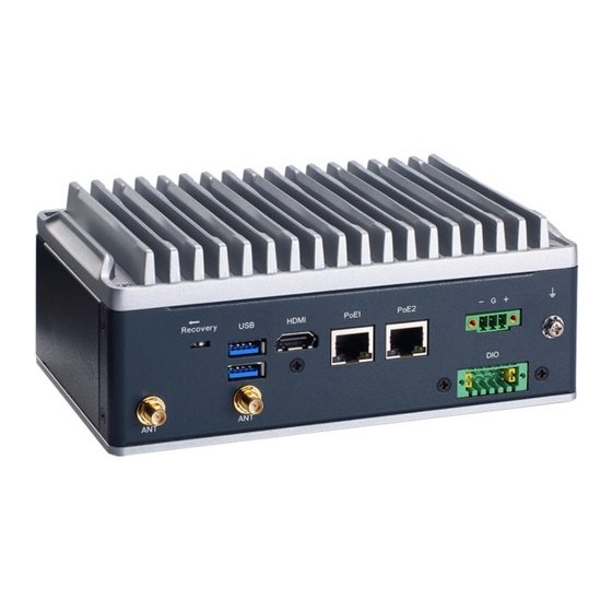
Page 20: I/O Outlets
AIE510-ONX Series User’s Manual I/O Outlets The following figures show you I/O outlets on front view of the AIE510-ONX. ⚫ Front View drawing: AIE510-ONX-16GB ⚫ Rear View drawing: AIE510-ONX-16GB Introduction... - Page 21 AIE510-ONX Series User’s Manual ⚫ Front View drawing: AIE510-ONX-GMSL ⚫ Rear View drawing: AIE510-ONX-GMSL Introduction...
-
Page 22: Packing List
Fanless Edge AI System with NVIDIA® Jetson Orin ™ NX AIE510-ONX-GMSL 16GB, 1 HDMI, 1 GbE PoE, 1 2.5 GbE PoE, 2 USB, 1 COM/CAN, Isolated DIO (4-in/4-out) and 4CH GMSL ※ If you cannot find this package or any items are missing, please contact Axiomtek distributors immediately. Introduction... -
Page 23: Optional Accessories
AIE510-ONX Series User’s Manual Optional Accessories Part Number Descripition Wall mount kit VESA mount kit DIN-rail mount kit M.2 NVMe SSD 128GB or above *The AIE510-ONX requires an SSD for image installation. Kindly order the SSD if you need image installation service. - Page 24 AIE510-ONX Series User’s Manual This page is intentionally left blank. Introduction...
-
Page 25: Section 2 Hardware Installation
AIE510-ONX Series User’s Manual SECTION 2 HARDWARE INSTALLATION The AIE510-ONX is convenient for your various hardware configurations, such as SSD (Solid State Drive), M.2 Key E module, M.2 Key B module, and PCI Express Mini Card modules. Chapter 2 will show you how to install the hardware. -
Page 26: Installing The Pci Express Mini Card
AIE510-ONX Series User’s Manual Installing the PCI Express Mini Card Step 1 Turn off the system, and unplug the power adapter. Step 2 Turn the system upside down to locate screws at the bottom side as red marked and loosen five screws. - Page 27 AIE510-ONX Series User’s Manual Step 4 Holding the PCI Express mini card at a 45 degree angle up from horizontal, slowly insert the golden fingers into the PCI Express slot until it is fully inserted in. Step 5 Press it down gently, but firmly, and then secure the PCI Express mini card to the carrier by tightening up the one M2 Phillips screw to the marked position.
- Page 28 AIE510-ONX Series User’s Manual Step 6 Connect the SMA cables to the PCI Express mini card. Hardware Installation...
-
Page 29: Installing The M.2 Key B 3042/3052 5G Or Lte Module
AIE510-ONX Series User’s Manual Installing the M.2 Key B 3042/3052 5G or LTE Module Step 1 Turn off the system, and unplug the power adapter. Step 2 Flip the system upside down and loosen five screws at the bottom side, as marked with red circles in the figure below. - Page 30 AIE510-ONX Series User’s Manual Step 4 Take the 5G thermal bracket, two thermal pads, and two M3 screws out of the package box. Step 5 Attach the two thermal pads onto the 5G thermal bracket. Note: Thermal Pad dimensions: ...
- Page 31 AIE510-ONX Series User’s Manual Step 6 Connect the SMA cables to the M.2 Key B module. Step 7 While holding the M.2 Key B 3052 module at a 30 degree angle up from the horizontal, slowly insert the golden fingers into the M.2 Key B 3042/3052 slot, until it is fully inserted in place.
- Page 32 AIE510-ONX Series User’s Manual Step 8 Press the M.2 Key B 3052 module down gently, but firmly, and then secure the module to the carrier by tightening up one M3 screw to the marked position. Note: M3 screw requires the tightening torque: 4.5~5.5Kgf -cm Step 9 Place the 5G thermal bracket on the M.2 Key B 3052 module, then...
-
Page 33: Installing The M.2 Key E 2230 Wi-Fi Module
AIE510-ONX Series User’s Manual Installing the M.2 Key E 2230 Wi-Fi Module Step 1 Connect the SMA cables to the M.2 Key E module. Step 2 Turn off the system, and unplug the power adapter. Step 3 Flip the system upside down and loosen five screws at the bottom side, as marked with red circles in the figure below. - Page 34 AIE510-ONX Series User’s Manual Step 4 Take off the bottom cover, and locate the M.2 2230 Key E slot on the carrier board. Step 5 While holding the M.2 Key E 2230 module at a 30 degree angle up from the horizontal, slowly insert the golden fingers into the M.2 Key E 2230 slot, until it...
- Page 35 AIE510-ONX Series User’s Manual Step 6 Press the M.2 Key E 2230 module down gently, but firmly, and then secure the module to the carrier by tightening up one M3 screw to the marked position. Hardware Installation...
-
Page 36: Installing 5G Or Lte Or Wi-Fi Antenna Cable
AIE510-ONX Series User’s Manual Installing 5G or LTE or Wi-Fi Antenna Cable Step 1 Install the Mini PCIe card or M.2 Key E card or M.2 Key B module, securing it with a screw and connecting it using SMA cables. For more details, please refer to section 2.1 to 2.3. - Page 37 AIE510-ONX Series User’s Manual Note: The 5G, LTE and Wi-Fi modules come with a different type of SMA cable, one is IPEX, and another one is IPEX4. Please do not mix them up to avoid mismatch. Step 2 Before installing the antenna cable onto the chassis, kindly remove the hex nut and washer.
- Page 38 AIE510-ONX Series User’s Manual Step 3 Install the antenna cable connectors through the openings on the chassis, put the washer and Hex nut into the antenna cable connector, and then tighten them up. Hardware Installation...
-
Page 39: Installing The M.2 2280 Key M Ssd Drive
AIE510-ONX Series User’s Manual Installing the M.2 2280 Key M SSD Drive Step 1 Turn off the system, and unplug the power adapter. Step 2 Flip the system upside down and loosen five screws at the bottom side, as marked with red circles in the figure below. - Page 40 AIE510-ONX Series User’s Manual Step 4 Take the SSD thermal bracket, four thermal pads, and two M3 screws out of the package box. Note: Thermal Pad dimensions: 60mm (L) x 25mm (W) x 2mm (H) 60mm (L) x 25mm (W) x 4.5mm (H) ...
- Page 41 AIE510-ONX Series User’s Manual Step 6 Apply two thermal pads onto the M.2 2280 Key M slot. Note: Thermal Pad dimensions: 60mm (L) x 25mm (W) x 4.5mm (H) 60mm (L) x 25mm (W) x 2.5mm (H) Step 7 While holding the M.2 2280 Key M SSD drive at a 30 -degree angle up from the horizontal, slowly insert the golden fingers into the M.2 2280...
- Page 42 AIE510-ONX Series User’s Manual Step 8 Press the M.2 2280 Key M SSD drive down gently, but firmly, and then secure the M.2 2280 Key M SSD drive to the carrier by tightening up one M3 screw to the marked position.
-
Page 43: Section 3 Connector & Pin Define
AIE510-ONX Series User’s Manual SECTION 3 CONNECTOR & PIN DEFINE This chapter contains connector information and detailed pin define of the AIE510-ONX. Connector Location PSB907 Top View Connector & Pin Define... - Page 44 AIE510-ONX Series User’s Manual PSB907 Bottom View Note: We strongly recommended that should modify unmentioned jumper setting without Axiomtek FAE’s instruction. Any modification without instruction might cause damage to the system. Connector & Pin Define...
-
Page 45: Connectors
Connectors connect the board with other parts of the system. Loose or improper connection might cause problems. Make sure all connectors are properly and firmly connected. Here is a summary table shows you all connectors, buttons and switches on the AIE510-ONX Series. Connectors / Buttons / Switches... -
Page 46: Fan Connector (Cn1)
AIE510-ONX Series User’s Manual 3.2.1 Fan Connector (CN1) The AIE510-ONX reserves an fan connector (CN1) for fan kit. Signal TACH 3.2.2 Debug & Serial & CAN Port Connector (CN2, CN3) AIE510-ONX features two DB9 connector for debug port and serial port (RS-232) as well as one CAN-bus port. -
Page 47: Isolated 4-In / 4-Out Digital I/O Connector (Cn4)
AIE510-ONX Series User’s Manual 3.2.3 Isolated 4-in / 4-out Digital I/O Connector (CN4) The AIE510-ONX supports one isolated 4-in / 4-out digital I/O (DIO). Signal Signal COM+ Ext. Power OUT 0 IN 0 OUT 1 IN 1 OUT 2 IN 2... -
Page 48: Ethernet & Poe Ports (Poe1, Poe2)
AIE510-ONX Series User’s Manual 3.2.5 Ethernet & PoE Ports (PoE1, PoE2) ® The AIE510-ONX comes with two RJ-45 connectors: PoE1 (NVIDIA Jetson Orin™ NX) and ® PoE2 (Intel I226-IT). Both of PoE1 and PoE2 are non-isolated PoE ports, which are compliant IEEE 802.3at Type 1 &... -
Page 49: Hdmi Connector (Cn13)
AIE510-ONX Series User’s Manual 3.2.6 HDMI Connector (CN13) The HDMI (High-Definition Multimedia Interface) is a compact digital interface which is capable of transmitting high-definition video and high-resolution audio over a single cable. Signal Signal HDMI1_DATA2+ HDMI1_DATA2- HDMI1_DATA1+ HDMI1_DATA1- HDMI1_DATA0+ HDMI1_DATA0-... -
Page 50: Ignition Connector (Ign)
AIE510-ONX Series User’s Manual 3.2.8 Ignition Connector (IGN) The AIE510-ONX supports a ignition connector for ignition power control. Function Ignition 3.2.9 GMSL Camera Connector (GMSL) The AIE510-ONX-GMSL features four FAKRA Z Code connectors located on the rear side. These connectors facilitate the GMSL1/2 (Gigabit Multimedia Serial Link) connections, enabling the seamless linkage of GMSL cameras to a two-port deserializer. -
Page 51: 2280 Key M Pcie X4 Ssd Slot (Scn1)
AIE510-ONX Series User’s Manual 3.2.10 M.2 2280 Key M PCIe x4 SSD slot (SCN1) The AIE510-ONX comes with one M.2 2280 Key M PCIe x4 NVMe SSD slot for storage. Signal Signal Signal Signal +3.3V +3.3V PEX3_RX- PEX3_RX+ LED_1# PEX3_TX- +3.3V... -
Page 52: 3042/3052 Key B 5G Module Slot (Scn2)
AIE510-ONX Series User’s Manual 3.2.11 M.2 3042/3052 Key B 5G module slot (SCN2) The AIE510-ONX comes with one M.2 3042/3052 Key B USB3.2 Gen2 (10Gbps) slot for 5G or LTE (CAT6 or above) module. Signal Signal Signal Signal Config_3 +3.3V +3.3V... -
Page 53: Pci-Express Mini Card Connector (Scn3)
AIE510-ONX Series User’s Manual 3.2.12 PCI-Express Mini Card Connector (SCN3) The AIE510-ONX supports a full-size PCI-Express Mini Card slots. SCN3 is applying to either PCI-Express or USB 2.0 signal, and complies with PCI-Express Mini Card Spec. V1.2. Signal Signal Signal... -
Page 54: 2230 Key E Slot (Scn4)
AIE510-ONX Series User’s Manual 3.2.13 M.2 2230 Key E slot (SCN4) The AIE510-ONX features one M.2 2230 Key E slot designed for Wi-Fi module usage. Signal Signal Signal Signal +3.3V USB_D+ +3.3V USB_D- CONNECTOR KEY E CONNECTOR CONNECTOR CONNECTOR CONNECTOR... -
Page 55: Nano Sim Card Slot (Scn5)
AIE510-ONX Series User’s Manual 3.2.14 Nano SIM Card Slot (SCN5) AIE510-ONX has a Nano SIM card slot (CN1). To make sure the system functions correctly, you need to use the Nano SIM card along with a 5G/LTE module. Please insert the LTE module into the PCI-Express Mini Card slot (SCN3) for LTE/3G networks. -
Page 56: Power Button & Reset Button (Sw2)
AIE510-ONX Series User’s Manual 3.2.16 Power Button & Reset Button (SW2) Power button can allow users to either turn on the AIE510-ONX or forcibly shut down the system, and the reset button can allow users to reset AIE510-ONX during system abnormal situation. -
Page 57: Cmos Battery Connector (Bat1)
AIE510-ONX Series User’s Manual 3.2.19 CMOS Battery Connector (BAT1) This connector is for CMOS battery interface. Signal +VBAT 3.2.20 Power and Storage LED Indicator (LED1) The Yellow LED is linked to Solid-state Drive (SSD) activity signal. LED flashes every time SSD is accessed. - Page 58 AIE510-ONX Series User’s Manual This page is intentionally left blank. Connector & Pin Define...
-
Page 59: Section 4 Jetpack Sdk
AIE510-ONX Series User’s Manual SECTION 4 JETPACK SDK This chapter provides users with a detailed description of how to flash NVIDIA Jetpack BSP for AIE510-ONX, the user could follow the below instruction to install or reinstall Jetpack BSP by themselves. - Page 60 AIE510-ONX Series User’s Manual Step2. Open the terminal at the host system, and change the path to the image file directory,e.g., “~/Downloads”, and check image tarball data integrity with the following commands: $ cd ~/Downloads $ md5sum -c <image_tarball_file_name>.tbz2.md5sum Command Example: $ md5sum -c mfi_jetson-orin-nx-16GB-JP5.1.2-AIE510-STD-V1.0.0.tbz2.md5sum...
- Page 61 AIE510-ONX Series User’s Manual Step6. Running the following command to flash the image. $sudo ./tools/kernel_flash/l4t_initrd_flash.sh -- flash-only --massflash 5 Step7. The flashing procedure takes approximately 8 minutes or more. Once finished, and AIE510-ONX will automatically reboot, and please switch the recovery switch(SW5) to OFF to return to standard mode.
-
Page 62: Image Information Inquiry Command
AIE510-ONX Series User’s Manual Image Information Inquiry Command axiomtek.sh Running command to inquiry the current image information, image version, L4T version, Linux kernel version, and Ubuntu version. Jetpack BSP Flash Method... -
Page 63: Jtop-Third-Party Jetson Platform Monitor Tool
AIE510-ONX Series User’s Manual JTOP-Third-party Jetson Platform Monitor Tool JTOP is a third-party system monitoring utility that runs on the terminal and see and control realtime the status of the AIE Series Platform. CPU, RAM, GPU status, power mode management, toolkits version and more. -
Page 64: Isaac - Nvidia Robotics Platform
AIE510-ONX Series User’s Manual ISAAC — NVIDIA ROBOTICS PLATFORM From smart automation in manufacturing to last -mile delivery, robots are becoming more ubiquitous in everyday life. However, industrial and commercial robotics development can be complex, time consuming, immensely challenging, and expensive. -
Page 65: Appendix A Programmable Digital I/O
AIE510-ONX Series User’s Manual APPENDIX A PROGRAMMABLE DIGITAL I/O About Programmable Digital I/O The AIE510-ONX supports isolated 4-in / 4-out programmable digital I/O which allows user to program the DI or DO. For more details, please refer to the below sample code. -
Page 66: Default Setting & Command Format
AIE510-ONX Series User’s Manual Default Setting & Command Format THE DEFAULT SETTING: DIO1 ~ 4 are all INPUT DIO5 ~ 8 are all OUTPUT Note: The DIO protocol will reset to the default setting after a cold boot. -
Page 67: Register Table
AIE510-ONX Series User’s Manual Register Table Register 0 - Input Port Register Bit Description Symbol Access Value Description Determined by externally applied read only logic level read only read only read only read only read only read only read only Register 1 - Output Port Register Bit Description This register reflects the outgoing logic levels of the pins defined as outputs by Register 3. - Page 68 AIE510-ONX Series User’s Manual Register 3 - Configuration Register Bit Description This register configures the directions of the I/O pins. If a bit in this register is set, the corresponding port pin is enabled as an input with high-impedance output driver. If a bit in this register is cleared, the corresponding port pin is enabled as an output.
-
Page 69: Digital Input & Output Wiring
AIE510-ONX Series User’s Manual Digital Input & Output Wiring Digital Input Wiring Logic Level 0: Close to ground ⚫ Logic Level 1: Open ⚫ Input Level For Dry Contacts Logic Level 1: +/-3VDC max. ⚫ Logic Level 0: +/- 10VDC min. to +/-30VDC max. - Page 70 AIE510-ONX Series User’s Manual Digital Output Wiring Programmable Digital I/O...
-
Page 71: Appendix B Ignition Power Control
AIE510-ONX Series User’s Manual APPENDIX B IGNITION POWER CONTROL About Ignition Power Control Please refer to the below link for more information: https://github.com/Axiomtek-AIE-SW/AIE510/tree/main/ignition THE DEFAULT SETTING: Voltage] VIN1: 237(mV) ADC Value: 153 R1: 2000 R2: 1818 [Current time sequence settings] ... - Page 72 AIE510-ONX Series User’s Manual This page is intentionally left blank. Ignition Power Control...
-
Page 73: Appendix C Gmsl Camera Guide (Aie510-Onx-Gmsl Only)
Only the vaildated cameras shown on the github are supported in default. https://github.com/Axiomtek-AIE-SW/AIE510/tree/main/camera Note: The vaildated cameras list may be subject to change without notice. For further support on GMSL cameras, please contact the Axiomtek FAE team. GMSL Camera Guide...
Need help?
Do you have a question about the AIE510-ONX Series and is the answer not in the manual?
Questions and answers