
Related Manuals for AXIOMTEK SHB160 Series


Summary of Contents for AXIOMTEK SHB160 Series
- Page 1 SHB160 Series ® Intel Socket 1700 Core i7/ i5/ i3 ® Processors PICMG v1.3 Full-size CPU Card User’s Manual...
- Page 2 Axiomtek does not make any commitment to update the information in this manual. Axiomtek reserves the right to change or revise this document and/or product at any time without notice. No part of this document may be reproduced, stored in a retrieval system, or transmitted, in any form or by any means, electronic, mechanical, photocopying, recording, or otherwise, without the prior written permission of Axiomtek Co., Ltd.
-
Page 3: Esd Precautions
Doing so can discharge static electricity from your body. ◼ Wear a grounding wrist strap, available from most electronic component stores, when handling boards and components. Trademarks Acknowledgments Axiomtek is a trademark of Axiomtek Co., Ltd. ® Intel Core i7/ i5/ i3 are trademarks of Intel Corporation. -
Page 4: Table Of Contents
Table of Contents Disclaimers ..................... ii ESD Precautions ................... iii Section 1 Introduction ............1 Features ....................1 Specifications ..................2 Packing list ..................3 Section 2 Board and Pin Assignments ......5 Board Layout ..................5 Block Diagram ..................6 Jumper Settings .................. - Page 5 BIOS ....................27 System Memory ................. 27 Section 5 AMI BIOS Setup Utility ........29 Starting ....................29 Navigation Keys ................29 Main Menu ..................31 Advanced Menu ................. 32 Chipset Menu ..................45 Security Menu ..................52 Boot Menu ..................53 Save &...
- Page 6 This page is intentionally left blank.
-
Page 7: Introduction
SHB160 LGA1700 Full-size CPU Card Section 1 Introduction ® The SHB160 PICMG v1.3 full-size Single Board Computer supports an LGA1700 socket for ® Intel Core i7/ i5/ i3 desktop processors. The transfer rate reaches 4400 MHz. The board ® integrates an Intel R680E/H610E chipset that delivers outstanding system performance through high-bandwidth interfaces, multiple I/O functions for interactive applications and various embedded computing solutions. -
Page 8: Specifications
UHD graphics supporting DVI-I ® ◼ Integrated Intel UHD graphics supporting DisplayPort (internal header) ◼ DVI/VGA: Max. resolution is 1920x1200 at 60 Hz. ◼ Internal DP1.4 Connector: Max resolution is 4096 x 2160 at 60Hz. Must use with Axiomtek DP kit. Introduction... -
Page 9: Packing List
All specifications and images are subject to change without notice. Note Packing list ⚫ 1 x slot CPU card ⚫ 1 x Driver DVD ⚫ 1 x SATA cable ⚫ 1 x COM cable **SHB160 series required specially designed cooler "711000001X00", please order as set** Introduction... - Page 10 SHB160 LGA1700 Full-size CPU Card This page is intentionally left blank. Introduction...
-
Page 11: Board And Pin Assignments
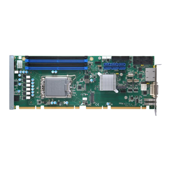
SHB160 LGA1700 Full-size CPU Card Section 2 Board and Pin Assignments Board Layout Top View Board and Pin Assignments... -
Page 12: Block Diagram
SHB160 LGA1700 Full-size CPU Card Block Diagram R680E Board and Pin Assignments... -
Page 13: Jumper Settings
The following illustration shows how to set up a jumper. Before applying power to the SHB160 series, please make sure all of the jumpers are in factory default position. Below you can find a summary table and onboard default settings. -
Page 14: Auto Power On (Jp1)
SHB160 LGA1700 Full-size CPU Card 2.3.1 Auto Power On (JP1) If JP3 is enabled for power input, the system will be automatically powered on without pressing soft power button. If JP1 is disabled for power input, it is necessary to manually press soft power button to power on the system. -
Page 15: Connectors
SHB160 LGA1700 Full-size CPU Card Connectors Signals go to other parts of the system through connectors. Loose or improper connection might cause problems. Make sure all connectors are properly and firmly connected. Here is a summary table showing all connectors on the board. Jumpers/Headers/Connectors ATX Power Connector (CN13) M.2 /E Key (2230)(CN27) -
Page 16: Temperature Sensor Connector (Cn15 And Cn16) (Optional)
SHB160 LGA1700 Full-size CPU Card 2.4.1 Temperature Sensor Connector (CN15 AND CN16) (Optional) This is a 2-pin connector for temperature sensor (NTC thermistor) interface. The thermistor value should be 10K and its B value is 3435K. Signal Sensor Input 2.4.2 Ethernet Ports (CN22) The board has two RJ-45 connectors: LAN1 (i226V) and LAN2 (i226LM). -
Page 17: Front Panel Connector (Cn26)
SHB160 LGA1700 Full-size CPU Card 2.4.3 Front Panel Connector (CN26) This is a front panel header (7x2-pin p=2.54mm). Signal PWRLED+ EXT SPK- Buzzer PWRLED- N.C. N.C. EXT SPK+ PWRSW- PWRSW+ HW RST- HW RST+ HDDLED- HDDLED+ Power LED Pin 1 connects anode(+) of LED and pin 5 connects cathode(-) of LED. The power LED lights up when the system is powered on. -
Page 18: Dvi-I Connector (Cn31)
SHB160 LGA1700 Full-size CPU Card 2.4.4 DVI-I Connector (CN31) DVI-I (integrated, combining digital and analog in the same connector; digital may be single or dual link) provides transmission of fast and high quality digital video from a source device (graphics card) to a display device. Signal Signal DVI_DATA2-... -
Page 19: Internal Usb 2.0 Connectors (Cn33)
SHB160 LGA1700 Full-size CPU Card 2.4.5 Internal USB 2.0 Connectors (CN33) These are 5x2-pin P=2.54mm headers for USB 2.0 interface. Signal Signal USB2_PWR78 USB2_PWR78 USB _IN USB _JN USB _IP USB _JP 2.4.6 Rear I/O USB 3.2 (Gen2x1, 10Gbps) Connectors (CN35 and CN36) These are standard USB (Universal Serial Bus) 3.0 connectors on the rear I/O for connecting USB peripherals such as a keyboard, mouse, scanner, etc. -
Page 20: Com Connectors (Com1~Com4)
SHB160 LGA1700 Full-size CPU Card 2.4.8 COM Connectors (COM1~COM4) This is a 10 pin (Pitch = 2.54mm) connector which is compliant with CATCH 1137-000- 10S. and it supports RS-232/RS-422/RS-485 mode operation for COM1 ~ COM4. See the table below for the pin assignments. RS-232 RS-422 RS-485... -
Page 21: Sata 3.0 Connectors (Cn10~Cn12/Cn17~19)
SHB160 LGA1700 Full-size CPU Card 2.4.10 SATA 3.0 Connectors (CN10~CN12/CN17~19) These Serial Advanced Technology Attachment (Serial ATA or SATA) connectors are for high-speed SATA 3.0 interfaces. They are computer bus interfaces for connecting to devices such as hard disk drives. This board has six SATA 3.0 ports with speed at 6Gb/s. -
Page 22: Tpm Pin Header (Cn7)
SHB160 LGA1700 Full-size CPU Card 2.4.13 TPM Pin Header (CN7) These are 7x2-pin p=2.0mm headers for SPI interface with an AX93515 TPM module. Signal Signal +3.3VDUAL 13 11 9 7 5 3 1 SPI_PCH_MOSI SPI_PCH_MOSI SPI_PCH_CLK SPI_PCH_CS2_N PLTRST_0_N SPI_TPM_IRQ SPI_TPM_PP 14 12 10 8 The screw type is M2*0.4. -
Page 23: Parallel Port Connector (Cn2)
SHB160 LGA1700 Full-size CPU Card 2.4.14 Parallel Port Connector (CN2) This board has a multi-mode parallel port to support: ⚫ Standard Mode: IBM PC/XT, PC/AT and PS/2 are compatible with a bi-directional parallel port. ⚫ Enhanced Mode: Enhance Parallel Port (EPP) is compatible with EPP 1.7 and EPP 1.9 (IEEE 1284 compliant). -
Page 24: 2280 Key M Nvme Ssd (Cn34)
SHB160 LGA1700 Full-size CPU Card 2.4.15 M.2 2280 Key M NVMe SSD (CN34) The M.2 2280 Key M NVM Express SSD for storage. Signal Signal Signal Signal +3.3V +3.3V PERn3 PERp3 LED_1# PETn3 +3.3V PETp3 +3.3V +3.3V PERn2 +3.3V PERp2 PETn2 PETp2 PERn1... -
Page 25: Internal Usb 3.2 Gen1X1 (5 Gbps) Connector (Cn24 And Cn25)
SHB160 LGA1700 Full-size CPU Card 2.4.16 Internal USB 3.2 Gen1x1 (5 Gbps) Connector (CN24 AND CN25) The CN24 and CN25 are internal box connectors for installing versatile USB 3.2 Gen1x1 compliant peripherals. And Connector is compliant with (LOTES AUSB0418-P001A) Signal Signal SSTX2+ SSTX3-... -
Page 26: Display Port 1.4 Connector (Cn30)
SHB160 LGA1700 Full-size CPU Card 2.4.17 Display Port 1.4 Connector (CN30) The CN11 is an internal box connector which is defined by Axiomtek for installing Display Port 1.4 Connector peripherals. The Display Port 1.4 Connector peripherals are available as an optional kit. -
Page 27: Hardware Installation
SHB160 LGA1700 Full-size CPU Card Section 3 Hardware Installation Installing the Processor The LGA1700 processor socket comes with a cover to protect the processor. Please install the processor into the CPU socket step by step as illustrated below: Make sure that you install the correct CPU only designed for the LGA1700 socket . DO NOT install a CPU designed for LGA1156, LGA1155 or LGA1150 CPU on the LGA1700 socket. - Page 28 SHB160 LGA1700 Full-size CPU Card Step 3 Processor installation: ⚫ Lift the processor package from shipping media by grasping the substrate edges. ⚫ Scan the processor package gold pads for any presence of foreign material. If necessary, the gold pads can be wiped clean with a soft lint-free cloth and isopropyl alcohol. ⚫...
- Page 29 SHB160 LGA1700 Full-size CPU Card Step 5 Step 6 Fan heatsink handling: Orientate the CPU cooling fan to fixing holes on the board. Screw the CPU cooling fan onto the board. Hardware Installation...
- Page 30 DO NOT recommend that you use the heat sink or cooler without verification, since it may cause damage or bend to the PCBA. Axiomtek’s heat sink or cooler has passed our testing including heat dissipation capacity.
- Page 31 Due to the weight of the cooler may cause the PCBA damage or unexpected issues. In addition, some applications highly require stability and Axiomtek suggests customer use a stand (as the red parts below) to support the cooler to prevent such issues.
-
Page 32: Installing The Memory
SHB160 LGA1700 Full-size CPU Card Installing the Memory The board supports four 288-pin DDR5 DIMM memory sockets with maximum memory capacity up to 128GB. Please follow steps below to install the memory modules: ⚫ Please insert your DDR5 memory modules from the CH0_DIMM1 slot first. ⚫... -
Page 33: Hardware Description
Make sure all correct settings are arranged for your installed microprocessor to prevent the CPU from damage. BIOS The SHB160 Series uses AMI Plug and Play BIOS with a single 256Mbit SPI Flash. System Memory The SHB160 Series supports four 288-pin DDR5 DIMM sockets for maximum memory capacity up to 128GB DDR5 SDRAMs. - Page 34 SHB160 LGA1700 Full-size CPU Card This page is intentionally left blank. Hardware Description...
-
Page 35: Ami Bios Setup Utility
SHB160 LGA1700 Full-size CPU Card Section 5 AMI BIOS Setup Utility The AMI UEFI BIOS provides users with a built-in setup program to modify basic system configuration. All configured parameters are stored in a flash chip to save the setup information whenever the power is turned off. - Page 36 SHB160 LGA1700 Full-size CPU Card Hot Keys Description → Left/Right The Left and Right <Arrow> keys allow you to select a setup screen. The Up and Down <Arrow> keys allow you to select a setup screen or sub- Up/Down screen.
-
Page 37: Main Menu
SHB160 LGA1700 Full-size CPU Card Main Menu The first time you enter the setup utility, you will enter the Main setup screen. You can always return to the Main setup screen by selecting the Main tab. System Time/Date can be set up as described below. -
Page 38: Advanced Menu
SHB160 LGA1700 Full-size CPU Card Advanced Menu The Advanced menu also allows users to set configuration of the CPU and other system devices. You can select any of the items in the left frame of the screen to go to the sub menus: ►... - Page 39 SHB160 LGA1700 Full-size CPU Card ⚫ ACPI Settings You can use this screen to select options for the ACPI Settings, and change the value of the selected option. A description of the selected item appears on the right side of the screen. For items marked with “”, please press <Enter>...
- Page 40 SHB160 LGA1700 Full-size CPU Card ⚫ Trusted Computing Enable or disable security device support. ⚫ Platform Misc Configuration This screen allows you to set Platform Misc Configuration. AMI BIOS Setup Utility...
- Page 41 SHB160 LGA1700 Full-size CPU Card ⚫ CPU Configuration This screen shows CPU information, and you can change the value of the selected option. AMI BIOS Setup Utility...
- Page 42 SHB160 LGA1700 Full-size CPU Card ⚫ Storage Configuration This screen shows storage information. ⚫ SATA Configuration During system boot up, the BIOS automatically detects the presence of SATA devices. In the SATA Configuration menu, you can see the hardware currently installed in the SATA ports.
- Page 43 SHB160 LGA1700 Full-size CPU Card SATA Controller(s) Enable or disable the SATA Controller feature. The default is Enabled. VMD Setup Menu VMD Configuration settings. The default is Disabled. AMI BIOS Setup Utility...
- Page 44 SHB160 LGA1700 Full-size CPU Card ⚫ NVMe Configuration This screen shows NVMe device information. ⚫ AMT Configuration This screen displays Active Management Technology information. AMI BIOS Setup Utility...
- Page 45 SHB160 LGA1700 Full-size CPU Card AMT BIOS Features Enable or disable Active Management Technology BIOS features. The default is Enabled. ⚫ F81966 Super IO Configuration You can use this screen to select options for the Super IO Configuration, and change the value of the selected option.
- Page 46 SHB160 LGA1700 Full-size CPU Card ⚫ Serial Port 1~4 Configuration Use these items to set parameters related to serial port 1 ~4 . ⚫ Parallel Port Configuration This screen displays Active Management Technology information. AMI BIOS Setup Utility...
- Page 47 SHB160 LGA1700 Full-size CPU Card ⚫ Hardware Monitor This screen monitors hardware health status. This screen displays the temperature of system and CPU, cooling fans speed in RPM and system voltages (VCC_CPU, DDR, +12V, +5V and +3.3V). AMI BIOS Setup Utility...
- Page 48 SHB160 LGA1700 Full-size CPU Card ⚫ Smart fan configuration This screen allows you to configure Smart Fan mode. You can use Smart Fan function to control Smart Fan. AMI BIOS Setup Utility...
- Page 49 SHB160 LGA1700 Full-size CPU Card ⚫ NCT7802Y Hardware Monitor This screen monitors Fans status. ⚫ USB Configuration This screen shows USB configuration. AMI BIOS Setup Utility...
- Page 50 SHB160 LGA1700 Full-size CPU Card ⚫ PCI Subsystem Settings This screen allows you to set PCI Subsystem mode. PCI Latency Timer Set the value to be programmed into PCI Latency Timer Register. VGA Palette Snoop Enables or Disables VGA Palette Registers Snooping. AMI BIOS Setup Utility...
-
Page 51: Chipset Menu
SHB160 LGA1700 Full-size CPU Card Chipset Menu The Chipset menu allows users to change the advanced chipset settings. You can select any of the items in the left frame of the screen to go to the sub menus: ► System Agent (SA) Configuration ►... - Page 52 SHB160 LGA1700 Full-size CPU Card ⚫ System Agent (SA) Configuration This screen shows System Agent information. VT-d Check to enable VT-d function on MCH. Above 4GB MMIO BIOS assignment Enable/Disable above 4GB Memory Mapped IO BIOS assignment \n\n. This is enabled automatically when Aperture Size is set to 2048MB.
- Page 53 SHB160 LGA1700 Full-size CPU Card ⚫ Graphics Configuration This screen shows graphics configuration. Internal Graphics Keep IGFX enabled based on the setup options. AMI BIOS Setup Utility...
- Page 54 SHB160 LGA1700 Full-size CPU Card ⚫ PEG Port Feature Configuration This screen allows you to set PEG Port. AMI BIOS Setup Utility...
- Page 55 SHB160 LGA1700 Full-size CPU Card ⚫ PCH-IO Configuration This screen allows you to set PCH parameters. PCI Express Configuration Configure PCIe Speed. HD Audio Configuration Enable or disable HD Audio. Wake on LAN Enable Enable or disable integrated LAN to wake the system. AMI BIOS Setup Utility...
- Page 56 SHB160 LGA1700 Full-size CPU Card ⚫ PCI Express Configuration This screen shows PCI Express configuration. AMI BIOS Setup Utility...
- Page 57 SHB160 LGA1700 Full-size CPU Card PCIe Speed Configure PCIe Speed. ASPM Set the ASPM Level: L1 - Force all links to L1 State. AUTO - BIOS auto configure. DISABLE - Disables ASPM. Detect Non-Compliance Device Detect Non-Compliance PCI Express Device. If enabled, it will take more time at POST time.
-
Page 58: Security Menu
SHB160 LGA1700 Full-size CPU Card Security Menu The Security menu allows users to change the security settings for the system. ⚫ Administrator Password This item indicates whether an administrator password has been set (installed or uninstalled). ⚫ User Password This item indicates whether a user password has been set (installed or uninstalled). ⚫... -
Page 59: Boot Menu
SHB160 LGA1700 Full-size CPU Card Boot Menu The Boot menu allows users to change boot options of the system. ⚫ Setup Prompt Timeout Number of seconds to wait for setup activation key. 65535(0xFFFF) means indefinite waiting. ⚫ Bootup NumLock State Use this item to select the power-on state for the keyboard NumLock. -
Page 60: Save & Exit Menu
SHB160 LGA1700 Full-size CPU Card Save & Exit Menu The Save & Exit menu allows users to load your system configuration with optimal or fail-safe default values. ⚫ Save Changes and Exit When you have completed the system configuration changes, select this option to leave Setup and return to Main Menu. - Page 61 SHB160 LGA1700 Full-size CPU Card ⚫ Save Changes When you have completed the system configuration changes, select this option to save changes. Select Save Changes from the Save & Exit menu and press <Enter>. Select Yes to save changes. ⚫ Discard Changes Select this option to quit Setup without making any permanent changes to the system configuration.
- Page 62 SHB160 LGA1700 Full-size CPU Card This page is intentionally left blank. AMI BIOS Setup Utility...
-
Page 63: Appendix A Watchdog Timer
SHB160 LGA1700 Full-size CPU Card Appendix A Watchdog Timer A.1 About Watchdog Timer Software stability is a major issue in most applications. Some embedded systems are not watched by humans for 24 hours. It is usually too slow to wait for someone to reboot when computer hangs. - Page 64 SHB160 LGA1700 Full-size CPU Card if (hinstLibDLL == NULL) hinstLibDLL = LoadLibrary(TEXT("diodll.dll")); if (hinstLibDLL == NULL) //MessageBox("Load diodll dll error", "", MB_OK); if (hinstLibDLL) lpFnDll_Get_IO = (LPFNDLLGETIOSPACE)GetProcAddress(GetModuleHandle("diodll.dll"), "GetIoSpaceByte"); lpFnDll_Set_IO = (LPFNDLLSETIOSPACE)GetProcAddress(GetModuleHandle("diodll.dll"), "SetIoSpaceByte"); printf("Input Watch Dog Timer type, 1:Second ; 2:Minute :"); scanf("%d",&unit);...
- Page 65 SHB160 LGA1700 Full-size CPU Card //set WDT Timer lpFnDll_Set_IO(0x2e, 0xF6); lpFnDll_Set_IO(0x2f, WDTtimer); //set watchdog time unit to min lpFnDll_Set_IO(0x2e, 0xF5); WDTDATA = lpFnDll_Get_IO(0x2f); WDTDATA = setbit(WDTDATA, 3); lpFnDll_Set_IO(0x2f, WDTDATA); //start watchdog counting lpFnDll_Set_IO(0x2e, 0xF5); WDTDATA = lpFnDll_Get_IO(0x2f); WDTDATA = setbit(WDTDATA, 5); lpFnDll_Set_IO(0x2f, WDTDATA);...
- Page 66 SHB160 LGA1700 Full-size CPU Card Note: If N=00h, the time base is set to second. M = time value 00h: Time-out Disable 01h: Time-out occurs after 1 second 02h: Time-out occurs after 2 seconds 03h: Time-out occurs after 3 seconds FFh: Time-out occurs after 255 seconds If N=08h, the time base is set to minute.
-
Page 67: Appendix Bvmd(Raid) Configuration
SHB160 LGA1700 Full-size CPU Card Appendix B VMD(RAID) Configuration How to Create Raid? Step 1 In SATA Configurations, enabled VMD Controller and save & reset. Step 2 After Restart, enter <del> to Bios Setup Menu. In Advanced Page, choose Intel(R) Rapid Storage Technology. - Page 68 SHB160 LGA1700 Full-size CPU Card Step 3 In Intel(R) Rapid Storage Technology page, choose RAID Volume. VMD(RAID) Configuration...
- Page 69 SHB160 LGA1700 Full-size CPU Card Step 4. Select the disk to be merged. Step5. Finally, implement create Volume. VMD(RAID) Configuration...
- Page 70 SHB160 LGA1700 Full-size CPU Card This page is intentionally left blank VMD(RAID) Configuration...
-
Page 71: Appendix Cpci Irq Routing
SHB160 LGA1700 Full-size CPU Card Appendix C PCI IRQ Routing ® C.1 PICMG PCI IRQ Routing Device Slot PCI Slot 0 BCDA PCI Slot 1 CDAB PCI Slot 2 DABC PCI Slot 3 ABCD PCI IRQ Routing... - Page 72 SHB160 LGA1700 Full-size CPU Card This page is intentionally left blank. PCI IRQ Routing...
-
Page 73: Appendix D Iamt Settings
SHB160 LGA1700 Full-size CPU Card Appendix D iAMT Settings ® ® The Intel Active Management Technology (Intel AMT) utilizes built-in platform capabilities and popular third-party management and security applications to allow IT administrators to remotely discover, repair and better protect their networked computing assets, thus significantly improving IT management efficiency. -
Page 74: Iamt Settings
SHB160 LGA1700 Full-size CPU Card iAMT Settings 1. Select Intel® AMT configuration, enable AMT BIOS features, then restart BIOS. 2. Go to MEBx page, enter thedefault password “admin” for first time login, then enter new password (complex password) twice to access AMT page. iAMT Settings... - Page 75 SHB160 LGA1700 Full-size CPU Card 3. Select Network Setup to configure iAMT. iAMT Settings...
- Page 76 SHB160 LGA1700 Full-size CPU Card ® 4. Go back to Intel AMT Configuration, then select Activate Network Access and press <Enter>. 5. Exit from MEBx after completing the iAMT settings. iAMT Settings...
-
Page 77: Iamt Web Console
SHB160 LGA1700 Full-size CPU Card iAMT Web Console 1. On a web browser, type http://(IP ADDRESS):16992, which directs to iAMT Web. Example: http://10.1.40.214:16992 2. To log in, you will be required to type in your username and password for access to the Web. - Page 78 SHB160 LGA1700 Full-size CPU Card 3. Enter the iAMT Web. 4. Click Remote Control, and select commands on the right side. 5. When you have finished using the iAMT Web console, close the Web browser. iAMT Settings...
-
Page 79: Picmg
SHB160 LGA1700 Full-size CPU Card Appendix E ® PICMG v1.3 Interface Definition x16 PCIe Connector A x16 PCIe Connector C Side B Side A Side B Side A USB0P USB0N USB1P USB1N WAKE# USB2P PWRBT# PME# USB2N PWRGD PSON# USB3P SHB_RST# PERST# USB3N... - Page 80 SHB160 LGA1700 Full-size CPU Card Mechanical Key b_PERp3 b_PERn3 REFCLK0+ REFCLK0- REFCLK1+ RSVD REFCLK1- REFCLK2+ REFCLK2- REFCLK3+ RSVD REFCLK3- REFCLK4+ REFCLK4- RSVD +3.3V +3.3V +3.3V +3.3V +3.3V +3.3V a_PETp0 +3.3V +3.3V a_PETn0 +3.3V +3.3V a_PERp0 +3.3V +3.3V a_PERn0 +3.3V +3.3V a_PETp1 +3.3V +3.3V...
- Page 81 SHB160 LGA1700 Full-size CPU Card Mechanical Key a_PETn3 a_PERp3 a_PERn3 a_PETp4 a_PETn4 a_PERp4 a_PERn4 a_PETp5 a_PETn5 a_PERp5 a_PERn5 a_PETp6 a_PETn6 a_PERp6 a_PERn6 a_PETp7 +12V +12V a_PETn7 +12V +12V a_PERp7 +12V +12V a_PERn7 +12V +12V +12V +12V +3.3V +3.3V +12V +12V +3.3V +3.3V +12V...
- Page 82 SHB160 LGA1700 Full-size CPU Card x8 PCIe Connector B x8 PCIe Connector D Side B Side A Side B Side A +5Vaux +5Vaux INTB# INTA# INTD# INTC# a_PETp8 a_PETn8 REQ3# GNT3# a_PERp8 REQ2# GNT2# a_PERn8 PCI_RST# GNT1# a_PETp9 REQ1# GNT0# a_PETn9 REQ0# SERR#...
- Page 83 SHB160 LGA1700 Full-size CPU Card Mechanical Key a_PETp14 C/BE2# a_PETn14 PCI_PRST# FRAME# a_PERp14 IRDY# TRDY# a_PERn14 DEVSEL# a_PETp15 LOCK# STOP# a_PETn15 PERR# a_PERp15 C/BE1# a_PERn15 AD14 AD12 AD15 AD10 AD13 AD09 AD11 C/BE0# AD08 +12V +12V AD06 +12V +12V AD07 AD05 +12V +12V...
- Page 84 SHB160 LGA1700 Full-size CPU Card This page is intentionally left blank. ® PICMG v1.3 Interface Definition...
- Page 85 SHB160 LGA1700 Full-size CPU Card Appendix F TPM Module Installation The TPM 2.0 (Trusted Platform Module 2.0) module is a modularized design applying to the SHB150R and provides enhanced hardware security for the computer. In this appendix you will learn how to install the TPM 2.0 module into the SHB150R. Please read and follow the instructions below carefully.
- Page 86 SHB160 LGA1700 Full-size CPU Card (In the Trusted Computing section, the first line will show “TPM2.0 Device Found”, if installation is successful.) b. In the Windows 10 OS environment, enter Device Manager, and select the item of Security devices. The screen will show “Trusted Platform Module 2.0” if the installation is successful.
- Page 87 SHB160 LGA1700 Full-size CPU Card c. In the Windows 10 OS environment, enter Control Panel, select the item of BitLocker Drive Encryption, and enter TPM Administration. The screen will show the information below if the installation is successful. TPM Module Installation...
Need help?
Do you have a question about the SHB160 Series and is the answer not in the manual?
Questions and answers