Table of Contents
Advertisement
Advertisement
Table of Contents

Related Manuals for AXIOMTEK SBC82610 SERIES


Summary of Contents for AXIOMTEK SBC82610 SERIES
- Page 1 SBC82610 Series Half-size All-in-One ISA CPU Card User’s Manual...
- Page 2 AXIOMTEK assumes no responsibility for any inaccuracies that may be contained in this document. AXIOMTEK makes no commitment to update or to keep current the information contained in this manual.
- Page 3 Wear a wrist-grounding strap, available from most electronic component stores, when handling boards and components. Trademarks Acknowledgments AXIOMTEK is a trademark of AXIOMTEK Co., Ltd. IBM is a registered trademark of International Business Machines Corporation. MS-DOS, and Windows ’95/98/NT/2000 are trademarks of Microsoft Corporation.
- Page 4 This page does not contain any information.
-
Page 5: Table Of Contents
Table of Contents Chapter 1 Introduction............1 1.1 General Description..........1 1.2 Specifications ............2 Chapter 2 Jumpers and Connectors.........5 2.1 Jumpers and Connectors Layout......5 2.2 Jumper Settings............7 2.2.1 Watchdog Timer Trigger Mode Setting: JP7 ... 8 2.2.2 CMOS Clear Jumper: JP5 ........8 2.2.3 Power Selection of Flat Panel Connector (VDDM of LCD1 and LCD2): JP6............ - Page 6 Chapter 3 Hardware Description........25 3.1 Microprocessors.............25 3.2 BIOS ..............25 3.3 I/O Port Address Map ..........26 3.4 Interrupt Controller..........27 3.5 VGA Interface ............28 3.6 Real Time Clock and CMOS RAM......28 3.7 PC/104 Connectors..........29 Chapter 4 Award BIOS Utility ........31 4.1 BIOS Introduction ...........31 4.2 BIOS Setup ..............31 4.3 Standard CMOS Setup ...........33 4.4 Advanced BIOS Features........37...
-
Page 7: Chapter 1 Introduction
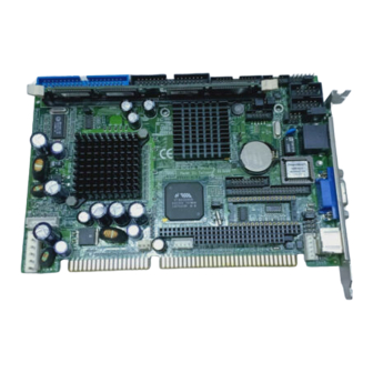
SBC82610 Half-size All-in-One CPU Card Series User’s Manual C h a p t e r 1 Introduction General Description The SBC82610 CPU card is an industrial grade CPU card incorporating the VIA VT8606 chipset and the VT82C686B with built- in AGP-4x VGA controller, both providing high performance and function-rich capability;... -
Page 8: Specifications
SBC82610 Half-size All-in-One CPU Card Series User’s Manual Specifications Processor: VIA EDEN 400MHz, 667MHZ,or C3 800MHZ CPU (other frequency processors are manufacturer optional) Chipset: VT8606 (Twister-T) + VT82C686B BIOS: AWARD BIOS, Plug-and-Play 4Mbit Flash ROM with SmartView VGA BIOS Function and integrated Ethernet Novell RPL and Windows PXE Boot ROM functions Standard I/O: Two serial ports;... - Page 9 SBC82610 Half-size All-in-One CPU Card Series User’s Manual Ethernet: Realtek 8139C PCI Bus 10/100M Base-T Wake On LAN (via ATX power supply) Onboard RJ-45 connector DiskOnChip: Supports 2~144 MB DiskOnChip series Expansion Slot: one 16-bit pc/104 connector AC97 Link: AC97 Link interface for external audio Codec Kit (AX93100) USB Interface: 2 USB ports with USB Spec.
- Page 10 This page does not contain any information.
-
Page 11: Chapter 2 Jumpers And Connectors
SBC82610 Half-size All-in-One CPU Card Series User’s Manual C h a p t e r 2 Jumpers and Connectors Jumpers and Connectors Layout The figure below shows the locations of all jumpers and connectors on the SBC82610VE. Jumpers and Connectors... - Page 12 SBC82610 Half-size All-in-One CPU Card Series User’s Manual Jumpers and Connectors...
-
Page 13: Jumper Settings
SBC82610 Half-size All-in-One CPU Card Series User’s Manual Jumper Settings The SBC82610VE is configured to match the needs of the application with the proper jumper settings. The table below is a summary of all the jumpers and their default settings for the onboard devices. Jumper Default Setting Jumper Setting... -
Page 14: Watchdog Timer Trigger Mode Setting: Jp7
SBC82610 Half-size All-in-One CPU Card Series User’s Manual 2.2.1 Watchdog Timer Trigger Mode Setting: JP7 The watchdog timer is an indispensable feature of the SBC82610VE. It has a sensitive error detection function and a report function. When the CPU processing comes to a halt, the watchdog either generates a NMI or resets the CPU. -
Page 15: 2.2.4 Com2 Rs232/422/485 Settings: Jp1, Jp2, Jp3
SBC82610 Half-size All-in-One CPU Card Series User’s Manual 2.2.4 COM2 RS232/422/485 Settings: JP1, JP2, JP3 COM4 Short 3-5, 4-6 Short 3-5, 4-6 Short 1-2 RS-232 (default) Short 1-3, 2-4 Short 1-3, 2-4 Short 3-4 RS-422 Short 1-3, 2-4 Short 1-3, 2-4 Short 5-6, 7-8 RS-485 JP1 and JP2... -
Page 16: Connectors
SBC82610 Half-size All-in-One CPU Card Series User’s Manual Connectors The connectors allow the CPU card to connect with other parts of the system. Ensure that all connectors are in place and firmly attached. The following table lists the function of each connector on the SBC82610VE. -
Page 17: Usb Connector: Cn3
SBC82610 Half-size All-in-One CPU Card Series User’s Manual 2.3.2 USB Connector: CN3 The Universal Serial Bus (USB) connector on the SBC82610VE is for installation of peripherals supporting the USB interface. CN3 is the 10-pin USB connector on the SBC82610VE. Description Description USB Power USB Power... - Page 18 SBC82610 Half-size All-in-One CPU Card Series User’s Manual Power LED This 2-pin connector, designated at Pins 1 and 3,5 of CN5, connects the system power LED indicator to its respective switch on the case. Pin 1 is +, and pin 3,5 is assigned as -. The Power LED lights up when the system is powered ON.
-
Page 19: Acpi Connector: Cn7
SBC82610 Half-size All-in-One CPU Card Series User’s Manual 2.3.4 ACPI Connector: CN7 Advanced Configuration and Power Interface (ACPI) defines a flexible and extensible interface that allows system designers to select appropriate cost/feature trade-offs for power management. The interface enables and supports reliable power management through improved hardware and operating system coordination. -
Page 20: Irda Connector: Cn8
SBC82610 Half-size All-in-One CPU Card Series User’s Manual 2.3.5 IrDA Connector: CN8 CN8 is a 5-pin IrDA connector for wireless communication. N.C. IRRX IRTX 2.3.6 Fan Connector: CN10 Description Speed Sensor +12V Jumpers and Connectors... -
Page 21: Keyboard And Ps/2 Mouse Connectors
SBC82610 Half-size All-in-One CPU Card Series User’s Manual 2.3.7 Keyboard and PS/2 Mouse Connectors The SBC82610VE provides a keyboard interface with a 5-pin connector. CN15, CN13 is a DIN connector for PS/2 keyboard and Mouse via “Y” Cable. CN15 CN13 Mouse Clock Keyboard Clock Clock... -
Page 22: Enhanced Ide Interface Connector: Ide1
SBC82610 Half-size All-in-One CPU Card Series User’s Manual 2.3.9 Enhanced IDE Interface Connector: IDE The SBC82610VE includes an ISA bus enhanced IDE controller that can support master/slave mode and post write transaction mechanisms with 64-byte buffer, and master data transaction. This feature, connected via connector IDE, allows the SBC82610VE to handle 2 IDE drives. -
Page 23: 2.3.10 Floppy Disk Controller: Fdd
SBC82610 Half-size All-in-One CPU Card Series User’s Manual 2.3.10 Floppy Disk Controller: FDD The SBC82610VE provides a 34-pin header type connector, FDD supporting up to two floppy drives. The floppy drives may be any one of the following types: 5.25" 360KB/1.2MB and 3.5" 720KB/1.44MB/2.88MB. -
Page 24: 2.3.11 Vga/Flat Panel Connector: Vga1, Lcd1, Lcd2
SBC82610 Half-size All-in-One CPU Card Series User’s Manual 2.3.11 VGA/Flat Panel Connector: VGA1, LCD1, LCD2 The SBC82610VE has three connectors that support CRT VGA and flat panel displays, individually or simultaneously. VGA1 is a standard 15-pin pin header connector commonly used for the CRT VGA display, and LCD1 (44-pin) LCD2 (20-pin) are dual-in-line headers for flat panel connection. - Page 25 SBC82610 Half-size All-in-One CPU Card Series User’s Manual LCD2: Flat Panel Connector for XVGA Description Description Description VDDM VDDM +12VM +12VM 2.3.11.1 Flat Panel Connector Pin Description Name Description P0~P35 Flat panel data output ENABKL Activity Indicator and Enable Backlight outputs Shift clock.
- Page 26 SBC82610 Half-size All-in-One CPU Card Series User’s Manual 2.3.11.2 Flat Panel Interface Pins for Color DSTN and Color TFT LCD DSTN 16-bit 24-bit 18-bit 24-bit HSYNC HSYNC VSYNC VSYNC SHFCLK ENAVDD ENAVDD ENAVDD ENAVDD ENAVDD ENABLK ENABLK ENABLK ENABLK ENABLK Jumpers and Connectors...
- Page 27 SBC82610 Half-size All-in-One CPU Card Series User’s Manual Pin Name TFT2X9 TFT2X12 TFT2X18 HSYNC VSYNC SHFCLK ENAVDD ENAVDD ENAVDD ENAVDD ENABLK ENABLK ENABLK ENABLK Jumpers and Connectors...
-
Page 28: 2.3.12 Serial Port Interface
SBC82610 Half-size All-in-One CPU Card Series User’s Manual Pin Name TFT2X9 TFT2X12 TFT2X18 2.3.12 Serial Port Interface The serial interface onboard SBC82610VE consists of COM1 or COMA1 port supports RS-232 and COM2 provide RS-232/422/485 connectivity. SBC82610VE uses two 10-pin connectors for COM2 and COM1 or a d-sub COMA1connector. -
Page 29: 2.3.13 Parallel Port Interface
SBC82610 Half-size All-in-One CPU Card Series User’s Manual NOTE: The COM1 and COM2, ports of SBC82610 are pin header type connectors whereas for SBC82610 COM1 is a DB-9 connector and com2 & a pin header 2.3.13 Parallel Port Interface The SBC82610VE onboard LPT1 is a multi-mode parallel port able to support: Standard mode: IBM PC/XT, PC/AT and PS/2... - Page 30 This page does not contain any information.
-
Page 31: Chapter 3 Hardware Description
SBC82610 Half-size All-in-One CPU Card Series User’s Manual C h a p t e r 3 Hardware Description This chapter gives a detailed explanation of the hardware features onboard the SBC82610VE CPU cards. Microprocessors The SBC82610VE supports VIA EDEN 400MHz, 667MHZ, or C3 800MHZ CPU (other frequency processors are manufacturer optional). -
Page 32: I/O Port Address Map
SBC82610 Half-size All-in-One CPU Card Series User’s Manual I/O Port Address Map The CPU card communicates via I/O ports. It has a total of 1KB port addresses that can be assigned to other devices via I/O expansion cards. Address Devices 000-01F DMA controller #1 Interrupt controller #1... -
Page 33: Interrupt Controller
SBC82610 Half-size All-in-One CPU Card Series User’s Manual Interrupt Controller The SBC82610VE is a fully PC compatible control board. It consists of 16 ISA interrupt request lines and 4 of the 16 can be either ISA or PCI. The mapping list of the 16 interrupt request lines is shown below; Parity check error IRQ0 System timer output... -
Page 34: Vga Interface
SBC82610 Half-size All-in-One CPU Card Series User’s Manual VGA Interface The Twister-T integrates S3 Graphics ’128-bit ProSavage4 graphics accelerator into a single chip. TwisterT brings mainstream graphics performance to the Value PC with leading-edge 2D, 3D and DVD video acceleration into a cost effective package. Based on its capabilities, Twister-T is an ideal solution for the consumer, corporate mobile users and entry level professionals. -
Page 35: Pc/104 Connectors
SBC82610 Half-size All-in-One CPU Card Series User’s Manual PC/104 Connectors The PC/104 is an industrial standard. It is a compact form factor with dimensions of 3.6” x 3.8” and is fully compatible with the ISA Bus. The PC/104 interface is able to adapt the off-the-shelf PC/104 modules, such as sound module, fax modem module and multi-I/O module…etc. - Page 36 This page does not contain any information.
-
Page 37: Chapter 4 Award Bios Utility
SBC82610 Half-size All-in-One CPU Card Series User’s Manual C h a p t e r 4 Award BIOS Utility Chapter 7 describes the different settings available in the Award BIOS that comes with the SBC82610VE CPU card. Also contained here are instructions on how to set up the BIOS configuration. - Page 38 SBC82610 Half-size All-in-One CPU Card Series User’s Manual When you enter the Setup utility, the Main Menu screen will appear on the screen. The Main Menu allows you to select from various setup functions and exit choices. Phoenix – AwardBIOS CMOS Setup Utility Standard CMOS Features Frequency/Voltage Control Advanced BIOS Features...
-
Page 39: Standard Cmos Setup
SBC82610 Half-size All-in-One CPU Card Series User’s Manual Standard CMOS Setup “Standard CMOS Setup” allows you to record some basic hardware configurations in your computer system and set the system clock and error handling. If the motherboard is already installed in a working system, you will not need to select this option. - Page 40 SBC82610 Half-size All-in-One CPU Card Series User’s Manual Date The date format is <day>, <date> <month> <year>. Press <F3> to show the calendar. The day of week, from Sun to Sat, determined by the BIOS, is read only The date, from 1 to 31 (or the maximum allowed in the month), can date key in the numerical / function key The month, Jan through Dec.
- Page 41 SBC82610 Half-size All-in-One CPU Card Series User’s Manual Drive A type/Drive B type The category identifies the types of floppy disk drive A or drive B installed in the computer. None No floppy drive installed 360K, 5.25 in 5.25 inch PC-type standard drive; 360Kb capacity 1.2M, 5.25 in 5.25 inch AT-type high-density drive;...
- Page 42 SBC82610 Half-size All-in-One CPU Card Series User’s Manual Halt On This field determines whether the system will halt if an error is detected during power up. The system boot will halt on any error detected. (default) No errors Whenever the BIOS detects a non-fatal error, the system All errors will stop and you will be prompted.
-
Page 43: Advanced Bios Features
SBC82610 Half-size All-in-One CPU Card Series User’s Manual Advanced BIOS Features This section allows you to configure and improve your system and allows you to set up some system features according to your preference. Phoenix – AwardBIOS CMOS Setup Utility Advanced BIOS Features Virus Warning Disabled... - Page 44 SBC82610 Half-size All-in-One CPU Card Series User’s Manual Virus Warning This item protects the boot sector and partition table of your hard disk against accidental modifications. If an attempt is made, the BIOS will halt the system and display a warning message. If this occurs, you can either allow the operation to continue or run an anti-virus program to locate and remove the problem.
- Page 45 SBC82610 Half-size All-in-One CPU Card Series User’s Manual Swap Floppy Drive This allows you to determine whether to enable Swap Floppy Drive or not. When enabled, the BIOS swaps floppy drive assignments so that Drive A becomes Drive B, and Drive B becomes Drive A. By default, this field is set to Disabled.
- Page 46 SBC82610 Half-size All-in-One CPU Card Series User’s Manual Typematic Rate (Chars/Sec) This option refers to the number of characters the keyboard can type per second. The default value is “6”. 6 characters per second 8 characters per second 10 characters per second 12 characters per second 15 characters per second 20 characters per second...
- Page 47 SBC82610 Half-size All-in-One CPU Card Series User’s Manual Video BIOS Shadow Video shadowing increases the video speed by copying the video BIOS into RAM. However, it is still optional depending on the chipset design. The default value of this option is “Enabled”. Enabled Video BIOS shadowing is enabled Disabled...
-
Page 48: Advanced Chipset Features
SBC82610 Half-size All-in-One CPU Card Series User’s Manual Advanced Chipset Features Since the features in this section are related to the chipset on the CPU board and are completely optimized, you are not recommended to change the default settings in this setup table unless you are well oriented with the chipset features. - Page 49 SBC82610 Half-size All-in-One CPU Card Series User’s Manual DRAM Clock This item allows you to select the DRAM clock value, depending on whether the board has paged DRAMs or EDO (extended data output) DRAMs. The available choices are 66 MHz and Host CLK. SDRAM Cycle Length When synchronous DRAM is installed, the number of clock cycles of CAS latency depends on the DRAM timing.
- Page 50 SBC82610 Half-size All-in-One CPU Card Series User’s Manual USB Keyboard Support Select Enabled if your system contains a Universal Serial Bus (USB) controller and you have a USB keyboard. The options available are Enabled, Disabled. CPU to PCI Write Buffer When this field is Enabled, writes from the CPU to the PCI bus are buffered, to compensate for the speed differences between the CPU and the PCI bus.
-
Page 51: Integrated Peripherals
SBC82610 Half-size All-in-One CPU Card Series User’s Manual Integrated Peripherals This option sets your hard disk configuration, mode and port. Phoenix – AwardBIOS CMOS Setup Utility Integrated Peripherals OnChip IDE Channel0 Enabled Item Help IDE Prefetch Mode Enabled Primary Master PIO Auto Menu Level Primary Slave PIO... - Page 52 SBC82610 Half-size All-in-One CPU Card Series User’s Manual accesses. If you install a primary and/or secondary add-in IDE interface, set this field to Disabled if the interface does not support prefetching. Primary Master/Slave PIO The four PIO (Programmed Input/Output) fields let you set a PIO mode (0-4) for each of the four IDE devices that the onboard IDE interface supports.
- Page 53 SBC82610 Half-size All-in-One CPU Card Series User’s Manual UART 2 Mode This item allows you to select UART mode. By default, this field is set to Standard. IR Function Duplex This item allows you to select the IR half/full duplex function. TX,RX inverting enable This item allows you to enable the TX, RX inverting which depends on different H/W requirement.
-
Page 54: Power Management Setup
SBC82610 Half-size All-in-One CPU Card Series User’s Manual Power Management Setup The Power Management Setup allows you to save energy of your system effectively. It will shut down the hard disk and turn OFF video display after a period of inactivity. Phoenix –... - Page 55 SBC82610 Half-size All-in-One CPU Card Series User’s Manual saving mode. Always On Monitor will remain on during power saving modes. Monitor blanked when the system enters the Suspend mode. Suspend --> Off Monitor blanked when the system enters either Suspend or Susp,Stby -->...
- Page 56 SBC82610 Half-size All-in-One CPU Card Series User’s Manual Soft-off by PWRBTN This only works with systems using an ATX power supply. It also allows user to define the type of soft power OFF sequence the system will follow. This option follows the conventional manner systems perform when power is Instant-Off turned OFF.
-
Page 57: Pnp/Pci Configuration
SBC82610 Half-size All-in-One CPU Card Series User’s Manual PNP/PCI Configuration This section describes the PCI bus system configuration. PCI or Personal Computer Interconnect is a system which allows I/O devices to operate at speeds nearing the speed of the CPU when communicating with its own special components. - Page 58 SBC82610 Half-size All-in-One CPU Card Series User’s Manual Resource controlled by The Award Plug and Play BIOS has the capacity to automatically configure all of the boot and Plug and Play compatible devices. However, this capability means absolutely nothing unless you are using a Plug and Play operating system such as Windows98.
-
Page 59: Pc Health Status
SBC82610 Half-size All-in-One CPU Card Series User’s Manual PC Health Status This section is to monitor the current hardware status of the CPU fan speeds and the core voltages. This is available only if there is hardware monitoring mechanism onboard. Phoenix –... -
Page 60: Frequency/Voltage Control
SBC82610 Half-size All-in-One CPU Card Series User’s Manual 4.10 Frequency/Voltage Control CMOS Setup Utility-Copyright © 1984-2001 Award Software Frequency/Voltage Control Auto Detect DIMM/PCI Clk Enabled Spread Spectrum Disabled Menu Level CPU Host/PCI Clock Default : Move Enter: Select +/-/PU/PD: Value F10: Save ESC: Exit F1: General Help F5: Previous Values F6: Fail-Safe Defaults F7: Optimized Defaults Auto Detect DIMM/PCI Clk When enabled, this item will auto detect if the DIMM and PCI socket have... -
Page 61: Load Fail-Safe Defaults
SBC82610 Half-size All-in-One CPU Card Series User’s Manual 4.11 Load Fail-Safe Defaults This option allows you to load the troubleshooting default values permanently stored in the BIOS ROM. These default settings are non- optimal and disable all high-performance features. Phoenix – AwardBIOS CMOS Setup Utility Standard CMOS Features Frequency/Voltage Control Advanced BIOS Features... -
Page 62: Load Optimized Defaults
SBC82610 Half-size All-in-One CPU Card Series User’s Manual 4.12 Load Optimized Defaults This option allows you to load the default values to your system configuration. These default settings are optimal and enable all high performance features. Phoenix – AwardBIOS CMOS Setup Utility Standard CMOS Features Frequency/Voltage Control Advanced BIOS Features... -
Page 63: Set Supervisor/User Password
SBC82610 Half-size All-in-One CPU Card Series User’s Manual 4.13 Set Supervisor/User Password You can set either supervisor or user password, or both of then. The differences between are: Supervisor password: can enter and change the options of the setup menus. User password: just can enter but do not have the right to change the options of the setup menus. -
Page 64: Save & Exit Setup
SBC82610 Half-size All-in-One CPU Card Series User’s Manual 4.14 Save & Exit Setup This allows you to determine whether or not to accept the modifications. Typing “Y” quits the setup utility and saves all changes into the CMOS memory. Typing “N” brigs you back to Setup utility. Phoenix –... -
Page 65: Exit Without Saving
SBC82610 Half-size All-in-One CPU Card Series User’s Manual 4.15 Exit Without Saving Select this option to exit the Setup utility without saving the changes you have made in this session. Typing “Y” will quit the Setup utility without saving the modifications. Typing “N” will return you to Setup utility. - Page 66 This page does not contain any information.
-
Page 67: Appendix A Watchdog Timer
SBC82610 Half-size All-in-One CPU Card Series User’s Manual A p p e n d i x A Watchdog Timer The SBC82610VE CPU card uses version 2.0 of the watchdog timer. This onboard WDT generates either a system reset or non-maskable interrupt (NMI), depending on the settings made on jumper JP7 of SBC82610VE. - Page 68 SBC82610 Half-size All-in-One CPU Card Series User’s Manual 0.5 sec. 5 secs. 50 secs. 100 secs. 1 sec. 10 secs. 100 secs. 200 secs. 1.5 secs. 15 secs. 150 secs. 300 secs. 2 secs. 20 secs. 200 secs. 400 secs. 2.5 secs.
-
Page 69: Appendix Bisa Golden Finger
SBC82610 Half-size All-in-One CPU Card Series User’s Manual A p p e n d i x B ISA Golden Finger The SBC82610VE provides a free ISA golden finger for expansion of ISA devices. Signal Signal Signal Signal -IOCHK -DACK2 RESDRV IRQ9 14.3MHz DREQ2...
Need help?
Do you have a question about the SBC82610 SERIES and is the answer not in the manual?
Questions and answers