
Related Manuals for AXIOMTEK CEM320


Summary of Contents for AXIOMTEK CEM320
- Page 1 CEM320 ® ® Intel Celeron N6210/ J6412 Processor ® Intel Atom X6414RE / X6413E Processor COM Express Type 10 Mini Module User’s Manual...
-
Page 2: Disclaimers
Axiomtek does not make any commitment to update the information in this manual. Axiomtek reserves the right to change or revise this document and/or product at any time without notice. No part of this document may be reproduced, stored in a retrieval system, or transmitted, in any form or by any means, electronic, mechanical, photocopying, recording, or otherwise, without the prior written permission of Axiomtek Co., Ltd. -
Page 3: Esd Precautions
It discharges static electricity from your body. ◼ Wear a wrist-grounding strap, available from most electronic component stores, when handling boards and components. Trademarks Acknowledgments Axiomtek is a trademark of Axiomtek Co., Ltd. ® Intel is a trademark of Intel Corporation. ®... -
Page 4: Table Of Contents
Table of Contents Disclaimers ..................... ii ESD Precautions ................... iii Section 1 Introduction ..........1 Features ....................1 Specifications ..................2 Utilities Supported ................3 Section 2 Module and Pin Assignments ....5 Module Dimensions and Fixing Holes ..........5 Module Layout .................. - Page 5 Save & Exit Menu ................52 Appendix A Watchdog Timer ........55 About Watchdog Timer ..............55 How to Use Watchdog Timer ............55 Appendix B Digital I/O ..........57 B.1 Digital I/O sample code: ................ 57 Appendix C BIOS Flash Utility ........ 59 Appendix D Block Diagram ........
- Page 6 This page is intentionally left blank.
-
Page 7: Introduction
X6414RE/X6413E processor. It delivers outstanding system performance and supports high speed I/Os like PCI-Express Gen 3 at 8GT/s, USB 3.2 gen2 at 10Gb/s, and SATA 3.0 at 6Gb/s. The CEM320 does fully comply with PICMG COM express Rev 3.0 COM Express Type 10 specification. -
Page 8: Specifications
CEM320 COM Express Type 10 Mini Module Specifications ⚫ ⚫ CEM320 - Intel ® Atom x6414RE 1.5GHz. ® - Intel Atom x6413E 1.5GHz. ® ® - Intel Celeron N6210 1.2GHz. ® ® - Intel Celeron J6412 2.0GHz. ⚫ BIOS ⚫... -
Page 9: Utilities Supported
CEM320 COM Express Type 10 Mini Module ⚫ Form Factor ⚫ Mini module 84mm x 55mm. Utilities Supported ⚫ Chipset driver ⚫ Graphics driver ⚫ Ethernet driver ⚫ USB 3.0 XHCI driver ⚫ Trusted Execution Engine ⚫ Sideband Fabric Device All specifications and images are subject to change without notice. - Page 10 CEM320 COM Express Type 10 Mini Module This page is intentionally left blank. Introduction...
-
Page 11: Module And Pin Assignments
CEM320 COM Express Type 10 Mini Module Section 2 Module and Pin Assignments Module Dimensions and Fixing Holes Top View Module and Pin Assignments... - Page 12 CEM320 COM Express Type 10 Mini Module Bottom View Module and Pin Assignments...
-
Page 13: Module Layout
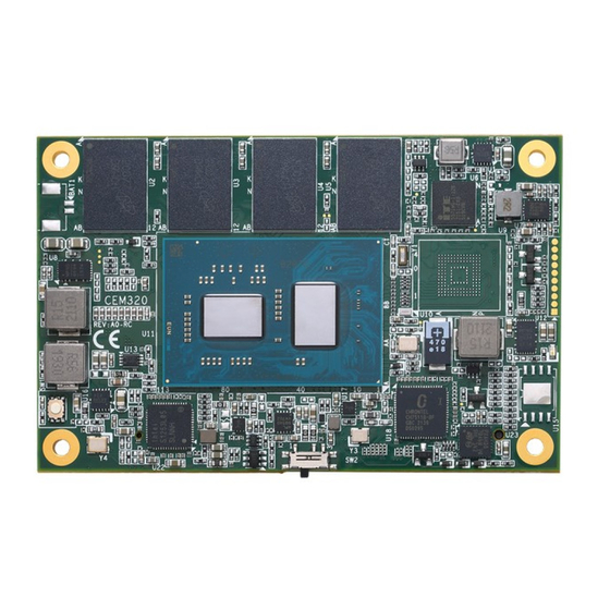
CEM320 COM Express Type 10 Mini Module Module Layout Top View Bottom View Module and Pin Assignments... -
Page 14: Installing Thermal Solution
CPU die. This CPU module has four assembly holes for installing heatspreader plate. Use the four screws to secure the heatspreader plate to the CEM320. Be careful not to over-tighten the screws. Then, apply thermal grease at the bottom of heatsink and secure the heatsink on the heatspreader by another four screws. -
Page 15: Switch Setting
Type 10 Mini Module Switch Setting Properly configure switch setting on the CEM320 to meet your application purpose. Below you can find a summary table of switch and onboard default setting. Once the default switch setting needs to be changed, please do it under power-off condition. -
Page 16: Connector
CEM320 COM Express Type 10 Mini Module Connector Signals go to the other parts of the system through connector. Loose or improper connection might cause problems, please make sure the COM Express connector is properly and firmly connected. Connector Description... -
Page 17: Cmos Battery Connector (Bat1)
CEM320 COM Express Type 10 Mini Module (S)ATA_ACT# RSVD LVDS_I2C_CK LVDS_BKLT_CTRL HDA_SYNC RSVD LVDS_I2C_DAT VCC_5V_SBY HDA_RST# HDA_SDIN0 GPI3/SD_DATA3 VCC_5V_SBY RSVD / Optional GND (FIXED) GND (FIXED) VCC_5V_SBY (PWR_SD_EN) HDA_BITCLK SPKR eDP_HPD# VCC_5V_SBY HDA_SDOUT I2C_CK PCIE_CK_REF+ BIOS_DIS1# BIOS_DIS0# I2C_DAT PCIE_CK_REF- DDI0_HPD... - Page 18 CEM320 COM Express Type 10 Mini Module This page is intentionally left blank. Module and Pin Assignments...
-
Page 19: Hardware Description
You must install the heatsink or cooler carefully and properly to prevent damage. BIOS The CEM320 uses AMI Plug and Play BIOS with a single 128Mbit SPI Flash. System Memory The CEM320 supports onboard LPDDR4 memory with maximum capacity up to 16GB. -
Page 20: I/O Port Address Map
CEM320 COM Express Type 10 Mini Module I/O Port Address Map The I/O port addresses (with CEB94017 baseboard under Windows ® 10) are as follows: Hardware Description... -
Page 21: Interrupt Controller (Irq) Map
CEM320 COM Express Type 10 Mini Module Interrupt Controller (IRQ) Map The interrupt controller (IRQ) mapping list (with CEB94017 baseboard under Windows 10) is ® shown as follows: Hardware Description... - Page 22 CEM320 COM Express Type 10 Mini Module Hardware Description...
- Page 23 CEM320 COM Express Type 10 Mini Module Hardware Description...
- Page 24 CEM320 COM Express Type 10 Mini Module Hardware Description...
- Page 25 CEM320 COM Express Type 10 Mini Module Hardware Description...
- Page 26 CEM320 COM Express Type 10 Mini Module Hardware Description...
- Page 27 CEM320 COM Express Type 10 Mini Module Hardware Description...
- Page 28 CEM320 COM Express Type 10 Mini Module Hardware Description...
- Page 29 CEM320 COM Express Type 10 Mini Module Hardware Description...
- Page 30 CEM320 COM Express Type 10 Mini Module Hardware Description...
- Page 31 CEM320 COM Express Type 10 Mini Module Hardware Description...
- Page 32 CEM320 COM Express Type 10 Mini Module Hardware Description...
- Page 33 CEM320 COM Express Type 10 Mini Module Hardware Description...
- Page 34 CEM320 COM Express Type 10 Mini Module Hardware Description...
-
Page 35: Memory Map
CEM320 COM Express Type 10 Mini Module Memory Map The memory (with CEB94017 baseboard under Windows ® 10) mapping list is shown as follows: Hardware Description... - Page 36 CEM320 COM Express Type 10 Mini Module Hardware Description...
-
Page 37: Ami Bios Setup Utility
CEM320 COM Express Type 10 Mini Module Section 4 AMI BIOS Setup Utility The AMI UEFI BIOS provides users with a built-in setup program to modify basic system configuration. All configured parameters are stored in a flash chip to save the setup information whenever the power is turned off. - Page 38 CEM320 COM Express Type 10 Mini Module Hot Keys Description → Left/Right The Left and Right <Arrow> keys allow you to select a setup screen. The Up and Down <Arrow> keys allow you to select a setup screen or sub ...
-
Page 39: Main Menu
CEM320 COM Express Type 10 Mini Module Main Menu When you first enter the setup utility, you will enter the Main setup screen. You can always return to the Main setup screen by selecting the Main tab. System Time/Date can be set up as described below. -
Page 40: Advanced Menu
CEM320 COM Express Type 10 Mini Module Advanced Menu The Advanced menu also allows users to set configuration of the CPU and other system devices. You can select any of the items in the left frame of the screen to go to the sub menus: ►... - Page 41 CEM320 COM Express Type 10 Mini Module You can use this screen to select options for DIO configuration. A description of selected item appears on the right side of the screen. For more details, see Appendix B. DIO Modification Enable or disable digital I/O modification. The default is Disabled.
- Page 42 CEM320 COM Express Type 10 Mini Module AMI BIOS Setup Utility...
- Page 43 CEM320 COM Express Type 10 Mini Module Serial Port Configuration ⚫ You can use this screen to select options for Serial Port Configuration, and change the value of the selected option. A description of the selected item appears on the right side of the screen.
- Page 44 CEM320 COM Express Type 10 Mini Module ⚫ Serial Port 1 Configuration Serial Port 1 (UART1) Enable or disable serial port 1. The optimal setting for base I/O address is 248h and for interrupt request address is IRQ7. Terminal mode Enable or disable terminal mode to enable/disable UR console function.
- Page 45 CEM320 COM Express Type 10 Mini Module Serial Port 2 Configuration Serial Port 2 (UART2) Enable or disable serial port 2. The optimal setting for base I/O address is 258h and for interrupt request address is IRQ6. Terminal mode Enable or disable terminal mode to enable/disable UR console function.
- Page 46 CEM320 COM Express Type 10 Mini Module ⚫ Hardware Monitor This screen is for hardware health status monitoring. This screen displays the temperature of system and CPU and system voltages (VBAT, +3.3V, +3.3VSB and +5VSB). AMI BIOS Setup Utility...
- Page 47 CEM320 COM Express Type 10 Mini Module ⚫ Trusted Computing You can use this screen for TPM (Trusted Platform Module) configuration. It also shows current TPM status information. Security Device Support Enable or disable BIOS support for security device. The default is Disabled.
- Page 48 CEM320 COM Express Type 10 Mini Module ⚫ CPU Configuration This screen shows CPU Configuration, and you can change the value of the selected option. Intel Virtualization Technology Enable or disable Intel Virtualization Technology. When enabled, a VMM (Virtual Machine Mode) can utilize the additional hardware capabilities.
- Page 49 CEM320 COM Express Type 10 Mini Module Intel® Speed Shifft Technology (Intel® SST) Enable or disable Intel SST to unlock turbo mode for more advanced performance. *Please make sure the thermal solution meet the requirements to resolve thermal energy in high performance.
- Page 50 CEM320 COM Express Type 10 Mini Module ⚫ Storage Configuration Access SATA/SDIO configuration in storage configuration menu to check/ set the parameters by need. AMI BIOS Setup Utility...
- Page 51 CEM320 COM Express Type 10 Mini Module ⚫ SATA Configuration In the SATA Configuration menu, you can see the currently installed hardware in the SATA ports. During system boot up, the BIOS automatically detects the presence of SATA devices. Chipset SATA Enable or disable the SATA Controller feature.
- Page 52 CEM320 COM Express Type 10 Mini Module SDIO Access Mode To select the access mode for SD device to strengthen compatibility. The default is Auto. eMMC selection. To select emulation type for eMMC device initialing. The default is Auto AMI BIOS Setup Utility...
- Page 53 CEM320 COM Express Type 10 Mini Module ⚫ USB Configuration This screen shows USB Configuration, and you can change the value of the selected option. USB Module Version Display USB module version information. USB Devices Display all detected USB devices.
-
Page 54: Chipset Menu
CEM320 COM Express Type 10 Mini Module Chipset Menu The Chipset menu allows users to change the advanced chipset settings. You can select any of the items in the left frame of the screen to go to the sub menus: LVDS Panel device Enable/ Disable for LVDS support. -
Page 55: Security Menu
CEM320 COM Express Type 10 Mini Module Security Menu The Security menu allows users to change the security settings for the system. Administrator Password This item indicates whether an administrator password has been set (installed or uninstalled). User Password This item indicates whether a user password has been set (installed or uninstalled). - Page 56 CEM320 COM Express Type 10 Mini Module ⚫ Secure boot Secure boot mode Enable secure boot mode to access key management and modify key setting by demand. Key management Enable or disable factory key provision AMI BIOS Setup Utility...
-
Page 57: Boot Menu
CEM320 COM Express Type 10 Mini Module Boot Menu The Boot menu allows users to change boot options of the system. ⚫ Setup Prompt Timeout Number of seconds to wait for setup activation key. 65535(0xFFFF) means indefinite waiting. ⚫ Bootup NumLock State Use this item to select the power-on state for the keyboard NumLock. -
Page 58: Save & Exit Menu
CEM320 COM Express Type 10 Mini Module Save & Exit Menu The Save & Exit menu allows users to load your system configuration with optimal or fail-safe default values. ⚫ Save Changes and Exit When you have completed the system configuration changes, select this option to leave Setup and return to Main Menu. - Page 59 CEM320 COM Express Type 10 Mini Module ⚫ Discard Changes Select this option to quit Setup without making any permanent changes to the system configuration. Select Discard Changes from the Save & Exit menu and press <Enter>. Select Yes to discard changes.
- Page 60 CEM320 COM Express Type 10 Mini Module This page is intentionally left blank. AMI BIOS Setup Utility...
-
Page 61: Appendix A Watchdog Timer
A.2 How to Use Watchdog Timer /*------------------------------------------------------------------ --------- $Workfile: AxiomWDT.cpp $ Copyright (c) 2020-21 Axiomtek Corporation This program contains proprietary and confidential information. All rights reserved except as may be permitted by prior written consent. Content:... - Page 62 CEM320 COM Express Type 10 Mini Module clrscr(); CurrentWdtTimer = inportw(AXIOM_WDT_TIMER); // Get current WDT Timer printf("Set Timer Seconds\n", DefaultTimer); printf("Current Timer: Seconds\n", CurrentWdtTimer); delay(1000); Watchdog Timer...
-
Page 63: Appendix B Digital I/O
Digital I/O B.1 Digital I/O sample code: /*--------------------------------------------------------------------------- $Workfile: AxiomDIO.cpp $ Copyright (c) 2020-21 Axiomtek Corporation This program contains proprietary and confidential information. All rights reserved except as may be permitted by prior written consent. Content: R E V I S I O N... - Page 64 CEM320 COM Express Type 10 Mini Module printf("DIO input/output set to 0x%X \n", DIO_DefaultInOutSetting); printf("BIT0-BIT3 is setting to input,BIT4-BIT7 is setting to output\n"); outportb(AXIOM_DIO_HIGH_LOW_ADDR, DIO_DefaultHighLowSetting); // Set DIO High/Low,1:High,0:Low,now is set to BIT0-BIT3 is Low,BIT4-BIT7 is High printf("DIO High/Low set to 0x%X \n", DIO_DefaultHighLowSetting);...
-
Page 65: Appendix Cbios Flash Utility
Please read and follow the instructions below carefully. In your USB flash drive, create a new folder and name it “Axiomtek”, see figure below. Copy BIOS ROM file (e.g. CEM320.005) to “Axiomtek” folder. - Page 66 Select the USB drive containing BIOS ROM file you want to update using the <> or <> key. Then press <Enter> to get into “Axiomtek” folder. Now you can see the BIOS ROM file on the screen, press <Enter> to select.
- Page 67 CEM320 COM Express Type 10 Mini Module Please wait while BIOS completes the entire flash update process: erase data, write new data and verify data. 10. When you see the following figure, press <Enter> to finish the update process. After that the system will shut down and restart immediately.
- Page 68 CEM320 COM Express Type 10 Mini Module This page is intentionally left blank. BIOS Flash Utility...
-
Page 69: Appendix D Block Diagram
CEM320 COM Express Type 10 Mini Module Appendix D Block Diagram Block Diagram... - Page 70 CEM320 COM Express Type 10 Mini Module This page is intentionally left blank. Block Diagram...
Need help?
Do you have a question about the CEM320 and is the answer not in the manual?
Questions and answers