TESTO 330 Instruction Manual
Flue gas analyser
Hide thumbs
Also See for 330:
- Instruction manual (84 pages) ,
- Update manual (8 pages) ,
- Instruction manual (78 pages)
Table of Contents
Advertisement
Quick Links
Advertisement
Table of Contents

Subscribe to Our Youtube Channel
Related Manuals for TESTO 330


Summary of Contents for TESTO 330
- Page 1 330 · Flue gas analyser Instruction manual...
- Page 2 Register your Testo product at www.testo.com/register and receive a one-year free warranty extension. The product registration is valid for 30 days after purchase. For product registration terms and conditions and participating countries, please go to www.testo.com/register...
-
Page 3: Table Of Contents
1 Contents Contents Contents ................3 Safety and the environment ..........7 2.1. About this document ............7 2.2. Ensure safety ..............8 2.3. Product-specific safety instructions ....... 10 2.4. Protecting the environment ..........10 Specifications ..............11 3.1. Use..................11 3.2. - Page 4 1 Contents 4.4. Modular flue gas probe ............ 32 First steps ................33 5.1. Commissioning ..............33 5.2. Getting to know the product ..........33 5.2.1. Mains unit / rech. batt..................... 33 5.2.1.1. Changing the rech. batt................33 5.2.1.2.
- Page 5 1 Contents 6.1.5. Programs ......................... 54 6.2. Measuring ................55 6.2.1. Preparing for measurement ................... 55 6.2.1.1. Zeroing phases ..................55 6.2.1.2. Using the modular flue gas probe ............56 6.2.1.3. Configuring the measurement view............57 6.2.1.4. Setting location and fuel ................. 57 6.2.2.
- Page 6 1 Contents 8.1. Questions and answers ........... 80 8.2. Accessories and spare parts .......... 81 8.3. Updating the instrument software ........85...
-
Page 7: Safety And The Environment
2 Safety and the environment Safety and the environment 2.1. About this document This document describes the products testo 330-1 LL and testo 330-2 LL with the device setting Country version | USA. > Please read this documentation through carefully and familiarize yourself with the product before putting it to use. -
Page 8: Ensure Safety
(158 °F), if these have not be specially approved for higher temperatures. > The testo 330 must be checked before commissioning for any visible damage. Do not commission the testo 330 if there are signs of damage on the housing, mains unit or supply lines. - Page 9 2 Safety and the environment Use distilled water, or alternatively mild solvents such as isopropanol to clean the flue gas analyzer. If using isopropanol, please refer to the instruction leaflet for the product. Isopropanol fumes have a slight narcotic effect, and typically cause irritation of the eyes and sensitive mucous membranes.
-
Page 10: Product-Specific Safety Instructions
> At the end of its useful life, send the product to the separate collection for electric and electronic devices (observe local regulations) or return the product to Testo for disposal. > The button cell used in the instrument contains 1,2- Dimethoxyethane (CAS 110-71-4). -
Page 11: Specifications
These systems can be adjusted using the testo 330 and checked for compliance with the applicable limit values. The following tasks can also be carried out with the testo 330: • Regulating the O2-, CO- and CO2-, NO-, NOx- data in furnace systems for the purpose of ensuring optimal operation. -
Page 12: Technical Data
As is common practice, Testo generally excludes support, warranty or guarantee claims relating to functionality that has not been guaranteed by Testo as part of the product offered. Claims shall also be excluded in the event of improper use or handling of the products, e.g. -
Page 13: Bluetooth ® -Type: Bluemod+Sr
The FCC demands that the user is to be informed that with any changes and modifications to the device, which have not been explicitly approved by testo SE & Co KGaA, the right of the user to use this device will become null and void. - Page 14 3 Specifications Country Comments Canada Contains FCC ID: 4957A-MSR Product IC ID: 6127B-2016T330 IC Warnings Contains FCC ID: RFRMS FCC ID: WAF-2016T330 FCC Warnings Europa + EFTA (Länderliste einfügen) EU countries: Belgium (BE), Bulgaria (BG), Denmark (DK), Germany (DE), Estonia (EE), Finland (FI), France (FR), Greece (GR), Ireland (IE), Italy (IT), Latvia (LV), Lithuania (LT), Luxembourg (LU), Malta (MT), Netherlands (NL), Austria (AT), Poland (PL), Portugal (PT), Romania (RO), Sweden (SE), Slovakia...
- Page 15 3 Specifications (1) This instrument must not cause any harmful interference and (2) this instrument must be able to cope with interference, even if this has undesirable effects on operation. Cet appareil satisfait à la partie 15B des directives FCC et au standard Industrie Canada RSS-210 (révision 8). Sa mise en service est soumise aux deux conditions suivantes : (1) cet appareil ne doit causer aucune interférence dangereuse et (2) cet appareil doit supporter toute interférence, y compris des interférences qui provoquerait des...
-
Page 16: Declaration Of Conformity
3 Specifications 3.2.3. Declaration of Conformity You can find the EU declaration of conformity on the Testo homepage www.testo.com under the product-specific downloads. -
Page 17: Measuring Ranges And Resolution
3 Specifications 3.2.4. Measuring ranges and resolution Parameter Measuring range Resolution 0...21 Vol.% 0.1 vol.% 0...4000 ppm 1 ppm CO, H -comp. 0...8000 ppm 1 ppm COlow 0...500 ppm 0.1 ppm CO amb 0...2000 ppm 1 ppm through flue gas probe CO amb with 0...500 ppm... -
Page 18: Accuracy And Response Time
3 Specifications 3.2.5. Accuracy and response time Parameter Accuracy Response time ±0.2 vol.% < 20 s (t90) ±20 ppm (0...400 ppm) < 60 s (t90) ±5 % of mv (401...2000 ppm) ±10 % of mv (2001...4000 ppm) CO, H -comp. ±10 ppm or ±10 % of mv <... -
Page 19: Other Device Data
3 Specifications Parameter Accuracy Response time Temperature ± 0.5 °C (0.0...100.0 °C) probe dependent ±0.5 % of mv (rest of range) Efficiency net Flue gas loss CO2a, through ±75 ppm + 3 % of mv approx. 35 s (0...5000 ppm) (t90) 0632 1240 ±150 ppm + 5 % of mv... - Page 20 Range < 10 m Warranty Measuring instrument: 48 months LL-sensors O2, CO: 48 months NO low sensor: 12 months Other sensors: 24 months Flue gas probe: 48 months Thermocouple: 12 months Rech. batt: 12 months Further warranty terms: see website www.testo.com/warranty...
-
Page 21: Product Description
Recommended for stowing away the measuring instrument and accessories (example) 4.1.1. Bottom level view 1 Sealing clip 2 testo 330-1 /-2 LL flue gas analyzer 3 Repository for printer accessories • Spare batteries for IRDA printer • 1 roll of spare thermal paper (0554 0568) 4 Repository for printer •... -
Page 22: Top Level View
4 Product description 7 Probes • Flue gas probe (e.g. 0600 9741) 8 Large storage compartment • Mains unit for testo 330-1 /-2 LL (0554 1096) • Differential temperature set (0554 1208) • Spare dirt filter (0554 0040) 9 Round storage compartment •... -
Page 23: Case 0516 3301 (Accessory)
4 Product description 4.2. Case 0516 3301 (accessory) Recommended for stowing away the measuring instrument and accessories (example) 4.2.1. Bottom level view 1 Fine pressure probe (0638 0330) 2 testo 308 smoke tester (0632 0308) -
Page 24: Middle Level View
4 Product description 4.2.2. Middle level view 1 Sealing clip 2 testo 330-1 /-2 LL flue gas analyzer 3 Repository for printer accessories • Spare batteries for IRDA printer • 1 roll of spare thermal paper (0554 0568) 4 Repository for printer •... -
Page 25: Top Level View
4 Product description 8 Large storage compartment • Mains unit for testo 330-1 /-2 LL (0554 1096) • Differential temperature set (0554 1208) • Spare dirt filter (0554 0040) 9 Round storage compartment • Hose connection set with pressure adapter (0554 1203) 4.2.3. -
Page 26: Measuring Instrument
4 Product description 4.3. Measuring instrument 4.3.1. Overview 1 Switch on/off 2 Interfaces: USB, PS2 (for devices until 2017), infrared CAUTION Risk of injury from infrared beam! > Do not direct infrared beam at human eyes! 3 Condensate trap (on rear) 4 Fixing eyelets for carrying strap (left and right) 5 Display... -
Page 27: Keypad
Function key (orange, 3x), relevant function is shown in the display Example [▲] Scroll up, increase data [▼] Scroll down, reduce data [esc] Back, cancel function Open main menu [ i ] Open instrument diagnosis menu Transmit data to the Testo protocol printer. -
Page 28: Display
4 Product description 4.3.3. Display 1 Status bar (dark gray background): • Display of date and time. • Indication of Bluetooth ® status, power supply and remaining capacity of the rech.batt.: Icon Feature blue symbol = Bluetooth ® gray symbol = Bluetooth ®... -
Page 29: Device Connections
4 Product description 4.3.4. Device connections 1 Probe socket 2 Flue gas socket 3 Mains unit socket 4 Pressure socket 4.3.5. Interfaces 1 USB interface 2 PS2-interface (for devices until 2017) 3 Infrared interface (IrDA) 4 Bluetooth interface (option) -
Page 30: Components
4 Product description 4.3.6. Components 1 Rech. batt. 2 Measuring gas pump 3 Slot for CO-sensor or COlow-sensor 4 Slot O2-sensor 5 Slot NO-sensor or NOlow-sensor 6 Additional filter... -
Page 31: Carrying Strap (0440 1001)
4 Product description 4.3.7. Carrying strap (0440 1001) To secure the carrying strap: > Remove the sealing caps from the sides of the housing. Fix the sealing caps on the inside of the service cover: 1. Place the measuring instrument on its front. 2. -
Page 32: Modular Flue Gas Probe
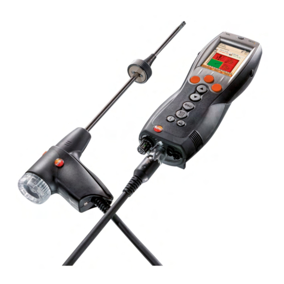
4 Product description 4.4. Modular flue gas probe 1 Removable filter chamber with window and particle filter 2 Probe handle 3 Connecting cable 4 Connector plug for measuring instrument 5 Probe module lock release 6 Probe module... -
Page 33: First Steps
4. Remove the battery and insert a new rech. batt. Only use the Testo rech. batt. 0515 0107! 5. Close the battery lock: Press the gray key and push against direction of arrow until the rech. batt. engages. -
Page 34: Charging The Rech. Batt
For longer measurements that are mains-operated, Testo recommends using a combustion air temperature probe with connecting cable. Self-heating of the instrument during mains operation may influence the combustion air temperature measurement with a mini ambient air probe. -
Page 35: Connecting Probes / Sensors
5 First steps 5.2.2. Connecting probes / sensors Probe/sensor detection at the flue gas socket is carried out continuously. New probes are recognised automatically. Connect a probe to the probe socket before switching on the measuring instrument or start sensor detection manually after changing the probe: [Options] →... -
Page 36: Switching On
5 First steps Connecting other sensors > Insert the connector plug of the probe into the probe socket. 5.2.3. Switching on The start screen is displayed (duration: about 5 s). If the voltage supply was interrupted for a longer period: The menu Date / Time is opened. -
Page 37: Entering Data
5 First steps 5.2.5. Entering data Some functions require data (numbers, units, characters) to be entered. Depending on the function that is chosen, the data are entered via either a list field or an input editor. List field 1. Select the value to be changed (numerical value, unit): [▲], [▼], [◄], [►] (depending on the selected function). -
Page 38: Show Graphic
5 First steps Input editor 1. Select the value to be changed (character): [▲], [▼], [◄], [►]. 2. Accept value: [OK]. Options: > Toggle between upper / lower case characters: ← → → → &$/ : [▲], [▼] [ABC &$/]. Select Ι... -
Page 39: Printing / Saving Data
5 First steps 5.2.7. Printing / saving data Save Assignment of the right function key with the function Print, see Assigning the right function key page 45 . Only meas. views, which have a display field in the measurement view assigned, will be saved / printed out. The measurement data can be printed out parallel to the saving process, while a measurement program is running. -
Page 40: Switching Off
5 First steps 5.2.10. Switching off Unsaved meas. views will be lost when the flue gas analyzer is switched off. Possibly: The pump starts and the sensors are rinsed until the switch-off thresholds (O2 > 20 %, other measurement parameters < 50 ppm) are reached. The maximal rinsing period is 3 minutes. - Page 41 5 First steps Show all 1. Select address: [▲], [▼]. 2. Show details: [Details]. [OK]. 3. Enable a location: select the location → The location is activated. > Open measurements menu: press [OK] again. Search 1. Edit search criteria: [►] →...
-
Page 42: Protocols
5 First steps Create a new measuring location: A location is always created under an address. 1. Select the address in which the location is to be created. [Options] New/Location → [OK]. → 3. Enter values or make settings. 4. Finalise the entry: [Finished]. Other location options: >... -
Page 43: Instrument Diagnosis
Instrument diagnosis Important operating data and instrument data are displayed. A gas path check (testo 330-2 LL) can be carried out. The status of the sensors and any Error Services not yet rectified can be displayed. Calling up the function: >... - Page 44 5 First steps Viewing sensor diagnosis: Sensor Diagnosis → [OK]. 1. > 2. Select sensor. [▲], [▼]. The status of the sensor is indicated by a lamp. A sensor is able to recover. It is therefore possible that the sensor status indication changes from yellow to green or from red to yellow.
-
Page 45: Using The Product
6 Using the product Using the product 6.1. Setting preferences 6.1.1. Assigning the right function key Options The right function key can have a function from the menu Options assigned to it. The menu is accessed via the left function key and is available in many different menus. - Page 46 6 Using the product Display Measurement parameter Carbon dioxide η+ Efficiency net under due consideration of the heat value range Carbon monoxide Carbon monoxide undiluted Nitrogen monoxide Nitrogen oxide ExAir Air ratio COamb Ambient carbon monoxide CO2a Ambient carbon dioxide O2ref Oxygen reference E-drft...
-
Page 47: Alarm Thresholds
6 Using the product Options: [Options] Number of Lines: Change the number of > → measuring values per display page. > [Options] → Insert Blank Lines: Insert the blank line before the selected line. > [Options] → Delete Line: Delete the selected line. >... -
Page 48: Date / Time
6 Using the product 6.1.2.4. Date / time Date, time mode and time can be set. Calling up the function: Device Settings [OK] Date/Time [OK] > → → → → Setting date/time: 1. Select parameter: [◄], [▲], [▼] → [Edit]. 2. -
Page 49: Printer
6 Using the product Show or hide measurement types: [▲], [▼] 1. Select measurement type: 2. Enable / disable measurement type: (enabled), (disabled) 3. Save selection: [Finished]. 6.1.2.8. Printer The headers (lines 1-3) and the footnotes for the printout can be set. -
Page 50: Language
The selection of the country version influences the menu languages that can be enabled. For information concerning the assignment table, the basis for calculation and the country version, see www.testo.com/download- center. Calling up the function: This action can be password protected. A password is... -
Page 51: Password Protection
6 Using the product 6.1.2.12. Password protection Password protection can be enabled / disabled, the password can be changed. 0000 To disable the password protection change the password to (factory setting). Calling up the function: Possibly: > Enter the currently valid password: [Enter] [Next] →... -
Page 52: O 2 Reference
6.1.3.4. Recalibration / adjustment CO and NO sensors can be recalibrated and adjusted. For recalibration / adjustment Testo recommends the use of the calibration adapter 0554 1205. If obviously unrealistic readings are displayed, the sensors should be checked (calibrated) and, if required, adjusted. -
Page 53: Fuels
Apart from the pre-configured fuels, 10 more customer specific fuels can be configured. Fuel parameter, see www.testo.com/download-center (registration required). In order to maintain the measuring accuracy of the instrument one must choose or configure the correct fuel. -
Page 54: Programs
6 Using the product Enabling fuels: > Select the fuel → [OK]. The fuel is enabled and the main menu is opened. Setting coefficients: 1. Select the fuel → [Coeff.]. 2. Select the coefficients: [Edit]. Possibly: > Enter the password: [Enter] →... -
Page 55: Measuring
When the instrument is switched on the measurement menu is opened and the gas sensors are zeroed. testo 330-1 LL: The flue gas probe must be in the open air during the zeroing phase! testo 330-2 LL: The flue gas probe can be in the flue gas duct even during the zeroing phase, if a separate VT- sensor is plugged in. -
Page 56: Using The Modular Flue Gas Probe
6 Using the product 6.2.1.2. Using the modular flue gas probe Checking the thermocouple The thermocouple of the flue gas probe must not lie against the probe cage. > Check before use. Bend the thermocouple back if necessary. Aligning the flue gas probe The flue gas must be able to flow freely past the thermocouple. -
Page 57: Configuring The Measurement View
6 Using the product 6.2.1.3. Configuring the measurement view Only those parameters and units which are enabled in the measurement view appear in the measurement view, the saved measurement protocols and the protocol printouts. > Before performing measurements set up the measurement view in such a way, that the required parameters and units are enabled, see Measurement view, page 45. - Page 58 [Options] → Accept measuring values from 315-3: Ambient CO/CO2 values measured with the testo 315-3 can be accepted by the testo 330. Data is transferred via Bluetooth® or via the IrDA interface. For data transfer via Bluetooth®, the testo 315 - 3 and the testo 330 - 2 must have this option, otherwise data is transferred via the IrDA interface.
- Page 59 6 Using the product Show flue gas matrix This function is only available if the measurement parameter has been enabled in the meas. view display. Calling up the function: ✓ The flue gas function is opened. [Options] Flue Gas Matrix: >...
-
Page 60: Draft-Measurement
6 Using the product 6.2.3. Draft-Measurement Calling up the function: ✓ A flue gas probe must be connected. Performing the measurement: The pressure socket of the instrument must be free (i.e. unpressurized, not closed). Do not measure for longer than 5 min, as the drift of the pressure sensor means that the meas. -
Page 61: Micro Pressure Probe
6 Using the product 6.2.4. Micro pressure probe The following measurements can be performed using the micro pressure probe (0638 0330): • Ext-Draught • Ext-Delta-P Single meas. • Ext-Delta Program See instruction manual for micro pressure probe. 6.2.5. CO undiluted Calling up the function: ✓... -
Page 62: Smoke No. / Hct
2. Enter data or values → [Next] or [OK]. Determining smoke tester no. / smoke nos. / oil derivative with the smoke tester testo 308 and transferring wireless: [Options] → t308. > The data recorded by the smoke tester are transferred to the testo 330. -
Page 63: Differential Pressure
(e.g. instrument must not be connected to the system to be tested), as the pressure sensor has to be zeroed first. Pressure zeroing. 2. Connect a silicone hose to the testo 330-2 and the system to be tested. The meas. view is displayed. Options: >... -
Page 64: Differential Temperature
6 Using the product 6.2.8. Differential temperature ✓ The differential temperature set (0554 1204) must be connected. Calling up the function: Performing the measurement: The meas. views and the calculated differential temperature (T1 T2) are displayed. Options: > [Options] → Clipboard: Data are saved to the clipboard. >... -
Page 65: Flowrate
6 Using the product Options: [Options] → Clipboard: Data are saved to the clipboard: > [Options] → Delete clipboard: Any data saved to the clipboard > is deleted. [Options] → Save: The meas. views are saved in a protocol. > [Options] Show Graphic: The meas. -
Page 66: Oil Flow
6 Using the product 6.2.11. Oil flow The function is only available if the chosen fuel is an oil. Calling up the function: Performing the measurement: Oil Flow 1. Select the parameters (of the oil nozzle) and Pressure (no effect on calculation): [▲], [▼] →... -
Page 67: Co2 Ambient
6 Using the product Performing the measurement: The measurement starts and the meas. view is displayed graphically (trend display). An audible alarm signal is triggered when the alarm limit is reached. 3. Confirm the message: [OK]. Options: [Options] → Clipboard: Data are saved to the clipboard. >... -
Page 68: Automatic Stokers
6 Using the product [Options] Alarm Limit: The alarm threshold menu is > → opened. > [Options] → Edit. Data for adjustable parameters can be edited. > [Options] → Sensor detection newly inserted sensor is detected. > [Options] → Measurement View: (This function is not available during a measurement) The measurement view menu is opened. -
Page 69: Gas Pipe Tests
6 Using the product Options [Options] → Clipboard: Data are saved to the clipboard. > [Options] → Delete clipboard: Any data saved to the clipboard > is deleted. [Options] → Save: The meas. views are saved in a protocol. > [Options] Adapter Information: Type and version of... -
Page 70: Main Test
6 Using the product Performing the measurement: ✓ The pressure socket of the instrument must be free (i.e. unpressurized, not closed). Leakage Rate Test → [OK]. Pressure zeroing. 2. Select parameter: [▲], [▼] → [Edit]. 3. Set parameters or enter data: [▲], [▼] and partly [◄], [►]... -
Page 71: Pretest
6 Using the product Performing the measurement: ✓ The pressure socket of the instrument must be free (i.e. unpressurized, not closed). Main Test → [OK]. 2. Select parameter: [▲], [▼] → [Edit]. 3. Set parameters or enter data: [▲], [▼] and partly [◄], [►] →... -
Page 72: Leak Detection
6 Using the product The stability time will run. After this the measuring phase starts automatically. > End stability time and measurement early: [Next]. The readings and Result Pretest are displayed when measurement has been completed. [Edit] → Select test result: [▲], [▼] →... -
Page 73: Transferring Data
Protocol printer To be able to transmit data via infrared or Bluetooth interface to a Testo protocol printer, the printer to be used must have been enabled, see Printer, page 49. Representation of the available characters per line is limited on the printout. -
Page 74: Maintaining The Product
7 Maintaining the product Maintaining the product 7.1. Cleaning the measuring instrument > If the housing of the measuring instrument is dirty, clean it with a damp cloth. Use distilled water, or alternatively mild solvents such as isopropanol to clean the flue gas analyzer. If using isopropanol, please refer to the instruction leaflet for the product. -
Page 75: Recalibrating / Adjusting Sensors
7 Maintaining the product leave the sensor without auxiliary circuit board for longer than 15 min. 5. Install new sensor / new bridge in the slot. 6. Plug the hose connections on sensor / bridge. 7. Attach the service cover and engage it in place. After replacing an O2 sensor, wait for an equalization period of 15 min to elapse before using the instrument again. - Page 76 7 Maintaining the product 5. Attach the service cover and engage it in place.
-
Page 77: Cleaning The Modular Flue Gas Probe
7 Maintaining the product 7.5. Cleaning the modular flue gas probe ✓ Disconnect the flue gas probe from the measuring instrument prior to cleaning. 1. Release the probe catch by pressing the key on the probe handle and remove the probe module. 2. -
Page 78: Changing The Thermocouple
7 Maintaining the product 7.7. Changing the thermocouple 1. Release the probe catch by pressing the key on the probe handle and remove the probe module. 2. Remove the thermocouple plug-in head from the socket using a screwdriver and pull the thermocouple out of the probe shaft. 3. -
Page 79: Checking / Replacing The Particle Filter
7 Maintaining the product 1. Unlock the condensate trap and pull it vertically off the meas. box. 2. Open the condensate outlet on the condensate trap: Pull out approx. 5 mm against the stop. 3. Let the condensate run out into a sink. 4. -
Page 80: Tips And Assistance
> Enable printer used, see Printer, page 49. • Switch on printer. > Move printer within wireless transmission range. If we could not answer your question, please contact your dealer or Testo Customer Service. Contact data see back of this document or website www.testo.com/service-contact. - Page 81 Modular flue gas probe 300 mm, 500 °C, 0600 9763 thermocouple 0.5 mm, probe shaft diameter: 6 mm Flexible flue gas probe, length 330 mm, Tmax. 0600 9770 180 °C, short-term 200 °C, bending radius max. 90° for measurements at difficult to access locations...
- Page 82 8 Tips and assistance Description Article no. Probe shaft module 700 mm, 1,000 °C, 0554 8765 thermocouple 1.0 mm, probe shaft diameter: 6 mm Spare thermocouple for module 0554 9760, 0430 9760 0554 9762 Spare thermocouple for module 0554 9761, 0430 9761 0554 9763 Spare thermocouple for module 0554 8764...
- Page 83 8 Tips and assistance Other probes / sensors Description Article no. O2 annular gap probe 0632 1260 Gas leak probe 0632 3330 Ambient CO probe 0632 3331 CO2 ambient probe (without connecting cable) 0632 1240 Connecting cable for CO2 ambient probe, 1.5 m 0430 0143 Gas pressure set: Draft path adapter, silicone hose 0554 1203...
- Page 84 Pressure test set for gas line testing 0554 1213 ISO Calibration Certificate Flue Gas 0520 0003 For a complete list of all accessories and spare parts, please refer to the product catalogs and brochures or look up our website www.testo.com...
- Page 85 Updating the instrument software Under www.testo.com/download-center you can download the current instrument software (Firmware) for testo 330 (registration required). > Unplug the mains unit and switch off the testo 330. 1. Hold [▲] depressed. 2. Plug in the mains unit, keep [▲]...
- Page 86 8 Tips and assistance...
- Page 88 0970 3319 en-US 13...
Need help?
Do you have a question about the 330 and is the answer not in the manual?
Questions and answers