
Related Manuals for TESTO 330i


Summary of Contents for TESTO 330i
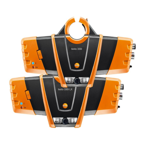
- Page 1 330i · Flue gas measuring instrument testo 330i LX · Flue gas measuring instrument Instruction manual...
-
Page 3: Table Of Contents
| Instrument settings | Sensor protection ..........17 6.1.7. | Instrument settings | O reference ............17 6.1.8. | Instrument settings | O addition ............17 6.1.9. | Instrument settings | Height compensation .......... 17 6.1.10. | Instrument settings | Switching the testo 330i off ......... 18... - Page 4 1 Contents 6.2. Measuring ..................18 6.2.1. Preparing for measurement ................18 6.2.1.1. Checking the condensate container fill level ........18 6.2.1.2. Checking the particle filter ............... 18 6.2.1.3. Zeroing phases ................18 6.2.1.4. Performing a gas path check ............19 6.2.1.5.
- Page 5 1 Contents Technical data ..................38 8.1.1. Examinations and licenses ................38 ® 8.1.2. Bluetooth module ..................38 8.1.3. Measuring ranges and resolution ..............42 8.1.4. Accuracy and response time ................42 8.1.5. Other instrument data ..................44 8.1.6. Declaration of conformity ................45 Tips and assistance ................
-
Page 6: Safety And The Environment
330i und testo 330i LX The testo 330i / testo 330i LX is a flue gas measuring instrument which in combination with a separate Android or iOS mobile device and the testo 330i App enables professional flue gas analysis of combustion systems: •... - Page 7 As is common practice, Testo generally excludes support, warranty or guarantee claims relating to functionality that has not been guaranteed by Testo as part of the product offered. Claims shall also be excluded in the event of improper use or handling of the products, e.g. in combination with unauthorised third-party products.
-
Page 8: Product Description
4 Product description Product description 4.1. Measuring instrument 4.1.1. Overview ® 1 Retaining bracket: for attaching to the probe mount testofix 2 Terminal panel left 3 Status LEDs: Display Meaning Blue Instrument off or not ready Flashes (0.05 s Instrument on, start up phase on/0.5 s off) ®... -
Page 9: Terminal Panel Left/Right
4 Product description 7. Magnetic holder (on rear) WARNING Magnetic field May be harmful to those with pacemakers. > Keep a minimum distance of 15 cm between pacemaker and instrument. ATTENTION Magnetic field Damage to other devices! > Keep a safe distance away from products that could be damaged by the effects of magnetism (e.g. -
Page 10: Modular Flue Gas Probe
4 Product description 4.2. Modular flue gas probe 1 Removable filter chamber with window and particle filter 2 Probe module lock release 3 Probe module 4 Connector plug for measuring instrument 5 Probe handle 6 Connecting cable... -
Page 11: First Steps
5 First steps First steps 5.1. Commissioning Please note the information in the document Commissioning and Safety (printed version supplied with the product). 5.2. Getting to know the product 5.2.1. Connecting probes Always connect the probes to the flue gas socket or probe socket before switching on the measuring instrument;... -
Page 12: Mains Operation
5.2.3. Switching on and connecting with a mobile terminal device ✓ The testo 330i App must be installed on your mobile terminal device. Please note the information in the document Commissioning and Safety (printed version supplied with the product). -
Page 13: Switching Off
If it is not possible to establish a connection, various corrective measures are displayed. If you are unable to implement these successfully, please refer to the section Tips and assistance and/or contact your dealer or Testo Customer Service. For contact details, please visit www.testo.com/service-contact. Measurement type Flue Gas screen is displayed. -
Page 14: Using The App
5 First steps 5.2.5. Using the App Make sure you are familiar with how your mobile terminal device works before using the App; observe the documentation for your mobile terminal device. Actions are mainly carried out by touching an icon, a symbol, or a name. -
Page 15: Using The Product
6 Using the product Using the product 6.1. Performing settings 6.1.1. Configuring measurements The measurement parameters/units and the number and order of displayed measurement parameters in the reading display type can be set in the List. Only those parameters and units that are enabled in the reading display appear in the measured value display, in the saved measurement records and on the record printouts. -
Page 16: Graphics
6 Using the product Display Measurement parameter Nitrogen oxide λ Fuel-air ratio AmbCO Ambient carbon monoxide Oxygen reference Dew Pt Flue gas dewpoint temperature Performing actions > To add a measurement parameter to the display list: Touch to open the selection list of measurement parameters. >... -
Page 17: Instrument Settings | Country Version
6 Using the product 6.1.4. | Instrument settings | Country version The Country version configuration affects the measurement parameters, fuels, fuel parameters, and the basis of and formulas for calculations activated in the measurement box. The country version setting affects the user screen languages that can be enabled. -
Page 18: Instrument Settings | Switching The Testo 330I Off
Altitude. 6.1.10. | Instrument settings | Switching the testo 330i off It is possible to switch the testo 330i off via the mobile terminal device. Measuring values that have not been saved are lost when the measuring instrument is switched off. -
Page 19: Performing A Gas Path Check
6 Using the product Gas zeroing The gas sensors are automatically zeroed when the instrument is switched on. > To manually start zeroing of the gas sensors: Zeroing Gas Sensors. Draught/pressure zeroing The pressure sensors are continuously zeroed. The flue gas probe can be in the flue gas duct during the zeroing phase, if there is no overpressure in the duct and a separate AT probe is plugged in. - Page 20 6 Using the product 2. Attach the probe mount to the flue gas duct by turning the fixing ring clockwise. 3. Slide the measuring instrument onto the probe mount up to the stop. 4. Check if the locking mechanism has latched into the probe mount.
-
Page 21: Using The Modular Flue Gas Probe
6 Using the product 5. Insert the flue gas probe through the probe mount into the flue gas duct. When using the testofix® probe mount, the measuring instrument is exposed to heat radiating from the flue gas duct during the measurement. In order to prevent consequently affecting the combustion air temperature a AT probe with cable must be used for the measurement! 6.2.1.6. -
Page 22: Flue Gas
6 Using the product Searching for the centre of flow The tip of the probe must be in the core current of the flue gas flow. Corestream 2. Align the flue gas probe in the flue gas duct so that the tip is in the core current (area of the highest flue gas temperature FT). -
Page 23: Draught
6 Using the product stopped/restarted. This draught measurement is performed separately to a measurement of the Draught measurement type. For the draught measurement, the minus connection for differential pressure measurements must be clear (ambient pressure, not closed). > Tap the draught reading display next to it. -
Page 24: Differential Temp
6 Using the product ✓ The gas pressure set (0554 1203) must be connected. ✓ The minus connection for differential pressure measurement must be depressurised at the beginning of measurement (ambient pressure; the instrument not connected to the system being checked), as the pressure sensor is zeroed. Zeroing the pressure sensor. -
Page 25: Oil Flow Rate
The calculated oil burner capacity (in kW) is displayed. 6.3. Printing readings The current readings can be printed using a report printer (accessories: Testo printer 0554 0621). Making print text settings The reading printout can be supplemented with individual information (header: company address; footer: name of technician). -
Page 26: Report
A report can be created of saved measurement data (readings) and other information about the measurement. Reports can be printed using a report printer (accessories: Testo printer 0554 0621) or sent as a file attachment in an email. The email application installed on the mobile terminal device is used for this. - Page 27 (comma separated text file, e.g. for ® Microsoft Excel), • • Print values (Testo printer 0554 0621 required (accessories)) • (XML file, complying with the regulations of the ‘Federal Association of Chimney Sweeps Germany’). Enter contact details or Import Contact Data...
-
Page 28: Maintaining The Product
7 Maintaining the product Maintaining the product 7.1. Checking instrument status 7.1.1. | Instrument settings | Sensor diagnosis The current status of the sensors can be displayed. To change expended sensors, see Replacing sensors , page 33. 7.1.2. | Error list Instrument errors that have not yet been rectified can be displayed. -
Page 29: Opening The Measuring Instrument
7 Maintaining the product CAUTION Condensate entering the gas path. Damage to sensors and flue gas pump! > Do not empty the condensate container while the flue gas pump is in operation. 1. Open the condensate outlet on the condensate container. 2. - Page 30 7 Maintaining the product 2. Use a cross-head screwdriver to remove the two (short) screws (1 and 2) from the retaining bracket. 3. Move the catch hook outwards (3) and push the back of the instrument up and lift off. >...
- Page 31 7 Maintaining the product 4. Remove the orange locking clips upwards out of the instrument casing (6). 5. Use a cross-head screwdriver to loosen and remove the 4 screws 7 to 10 (short screws) and the 4 screws 11 to 14 (long screws).
- Page 32 7 Maintaining the product 8. Fold up/back the upper instrument casing and place next to the lower casing (16). Do this carefully to prevent damaging hoses and lines. Assembly Perform in reverse order to assemble. Please note: > Lay hoses and lines in the designated ducts. >...
-
Page 33: Replacing The Rechargeable Battery
(2). 2. Remove the battery and insert a new rechargeable battery. Use only Testo rechargeable battery 0515 0107! 3. Close the battery lock: Press the grey button and push to the right keeping the button pressed until the battery engages. -
Page 34: Cleaning The Modular Flue Gas Probe
7 Maintaining the product 2. Remove the faulty sensor/bridge from the slot. > For NO sensor: Remove the auxiliary circuit board. Do not remove the auxiliary circuit board for the NO sensor until immediately before installation. Do not leave the sensor without auxiliary circuit board for longer than 15 minutes. -
Page 35: Replacing The Probe Module
7 Maintaining the product 7.8. Replacing the probe module ✓ Disconnect the flue gas probe from the measuring instrument. 1. Press the button on the top of the probe handle (1) and remove the probe module (2). 2. Plug in the new probe module and lock it in place (3). 7.9. -
Page 36: Changing The Thermocouple
7 Maintaining the product 1. Open the filter chamber: turn slightly anti-clockwise (1). Remove the filter chamber (2). 2. Remove the filter plate (3) and replace it with a new one (4 [0554 3385]). 3. Attach the filter chamber and lock it: turn slightly clockwise. 7.10. -
Page 37: Updating The Instrument Software
7.11. Updating the instrument software The current instrument software (firmware) you can find on the Testo homepage www.testo.com under the product-specific downloads. ✓ The measuring instrument must be switched off. 1. Plug the measuring instrument mains unit into a mains socket. -
Page 38: Technical Data
Examinations and licenses As declared in the Certificate of Conformity, this product complies with Directive 2014/30/EU. testo 330i / testo 330i LX with gas sensors O /CO, H compensated/NO, combustion air temperature sensor, flue gas temperature sensor and differential pressure sensor (draught) is TüV-tested in accordance with VDI 4206. - Page 39 CMIIT ID: 2016DJ4930 Europa + EFTA The EU Declaration of Conformity can be found on the testo homepage www.testo.com under the product specific downloads. EU countries: Belgium (BE), Bulgaria (BG), Denmark (DK), Germany (DE), Estonia (EE), Finland (FI), France (FR), Greece...
- Page 40 8 Technical data Contains FCC ID: RFRMS FCC ID: WAF-2016t330i FCC Warnings Bluetooth Feature Values SIG List Bluetooth Range < 10 m /< 32.8ft. Bluetooth type BlueMod+SR (August 2013) 4.0 Bluetooth® Classic / Low Enery Qualified Design ID B021281 Bluetooth company Stollmann E+V GmbH RF Band 2402-2480MHz...
- Page 41 8 Technical data FCC warning statement This equipment has been tested and found to comply with the limits for a Class B digital device, pursuant to Part 15 of the FCC Rules. These limits are designed to provide reasonable protection against harmful interference in a residential installation.
-
Page 42: Measuring Ranges And Resolution
8 Technical data 8.1.3. Measuring ranges and resolution Measurement Measuring range Resolution parameter 0 to 21 vol.% 0.1 vol.% 0 to 4,000 ppm 1 ppm 0 to 8,000 ppm 1 ppm -compensated) 0 to 30,000 ppm 1 ppm -compensated) with fresh air dilution 0 to 500 ppm 0.1 ppm... - Page 43 8 Technical data Measurement Accuracy Response parameter time CO H ± 10 ppm or ± 10% of m.v. (0 to < 60 s (t90) compensated 200 ppm) ± 20 ppm or ± 5% of m.v. (201 to 2,000 ppm) ± 10% of m.v. (2,001 to 8,000 ppm) CO (H ±...
-
Page 44: Other Instrument Data
8 Technical data 8.1.5. Other instrument data Flue gas analyzer Feature Values Storage and -20 to 50 °C transport temperature Operating -5 to 45 °C temperature Max. surface 140 °C temperature at the measurement aperture (with probe mount) Ambient humidity 0 to 90% RH, non-condensing Operating positions No restriction Fill level of... -
Page 45: Declaration Of Conformity
Other sensors: 24 months Flue gas probe: 48 months Thermocouple: 12 months Rechargeable battery: 12 months Further warranty terms: see website www.testo.com/warranty 8.1.6. Declaration of conformity You can find the EU declaration of conformity on the Testo homepage www.testo.com under the product-specific downloads. -
Page 46: Tips And Assistance
> Move printer into wireless range. Device error: Three acoustic signals after switching on the > Consult Testo Service or your measuring instrument dealer. > Open the overview of active App no longer responds to applications (refer to your... - Page 47 9 Tips and assistance Question Possible causes/solution > Keep the button pressed down for It cannot establish a Bluetooth connection! 10 s to reset and reboot the measuring instrument. Required instrument is not in the Find Device display. > Check the Bluetooth settings on No instruments are shown the mobile terminal device.
-
Page 48: Contact And Support
If we have not been able to answer your question, please contact your dealer or Testo Customer Service. For contact details, please visit www.testo.com/service-contact. You can also send Testo an error report via e-mail. In the Help menu, select Send error report. - Page 49 9 Tips and assistance Probe modules/accessories for modular flue gas probes Description Article no. Probe shaft module 180 mm, 500 °C, thermocouple 0554 9760 0.5 mm, probe shaft diameter: 8 mm Probe shaft module 300 mm, 500 °C, thermocouple 0554 9761 0.5 mm, probe shaft diameter: 8 mm Spare thermocouple for module 0554 9760, 0430 9760...
- Page 50 9 Tips and assistance Description Article no. Smoke pump tester, incl. oil, soot plates, for 0554 0307 measuring soot in flue gas Retrofit/spare sensors Description Article no. sensor 0393 0002 CO sensor 0393 0051 CO sensor H -compensated 0393 0101 sensor 0393 0103 NO sensor...
- Page 51 Pressure test set for gas pipe testing 0554 1213 ISO calibration certificate for flue gas 0520 0003 For a complete list of all accessories and spare parts, please refer to the product catalogues and brochures or visit our website www.testo.com...
- Page 52 0971 3340 en 04 en-GB...
Need help?
Do you have a question about the 330i and is the answer not in the manual?
Questions and answers