Table of Contents
Advertisement
Quick Links
Advertisement
Table of Contents

Related Manuals for TESTO 330 LX


Summary of Contents for TESTO 330 LX
- Page 1 330 LX · Flue gas analyzer Instruction manual...
-
Page 3: Table Of Contents
1 Contents Contents Contents ....................3 Safety and the environment ..............6 2.1. About this document ................ 6 2.2. Ensure safety ................... 7 2.3. Protecting the environment .............. 8 Specifications ..................9 3.1. Use ....................9 3.2. Technical data ................10 3.2.1. - Page 4 1 Contents First steps ....................29 5.1. Commissioning ................29 5.2. Getting to know the product ............29 5.2.1. Mains unit / rechargeable battery ..............29 5.2.1.1. Changing the battery ............... 29 5.2.1.2. Charging batteries ................30 5.2.1.3. Mains operation ................30 5.2.2.
- Page 5 6.2.2. Flue gas ......................51 6.2.3. Draught-Measurement ................... 53 6.2.4. Micro pressure probe ..................54 6.2.5. BImSchV (testo 330-2 LX) ................55 6.2.6. CO undiluted ....................56 6.2.7. Smoke No. / HCT ................... 56 6.2.8. Differential pressure ..................57 6.2.9.
-
Page 6: Safety And The Environment
2 Safety and the environment Safety and the environment 2.1. About this document This document describes the products testo 330-1 LX and testo 330-2 LX with the instrument setting Country version Germany. > Please read this documentation through carefully and familiarize yourself with the product before putting it to use. -
Page 7: Ensure Safety
70 °C unless they are expressly permitted for higher temperatures. > The testo 330 LX must be checked before commissioning for any visible damage. Do not commission the testo 330 LX if there are signs of damage on the housing, mains unit or supply lines. -
Page 8: Protecting The Environment
> At the end of its useful life, send the product to the separate collection for electric and electronic devices (observe local regulations) or return the product to Testo for disposal. > The button cell used in the instrument contains 1,2- Dimethoxyethane (CAS 110-71-4). -
Page 9: Specifications
These systems can be adjusted using the testo 330 LX and checked for compliance with the applicable limit values. The following tasks can also be carried out with the testo 330 LX: • Regulating the O2-, CO- and CO2-, NO-, NOx- values in furnace systems for the purpose of ensuring optimal operation. -
Page 10: Technical Data
3 Specifications has not been guaranteed by Testo as part of the product offered. Claims shall also be excluded in the event of improper use or handling of the products, e.g. in combination with unauthorised third-party products. testo 330 LX must not be used: •... - Page 11 3 Specifications Europa + EFTA EU countries: Belgium (BE), Bulgaria (BG), Denmark (DK), Germany (DE), Estonia (EE), Finland (FI), France (FR), Greece (GR), Ireland (IE), Italy (IT), Latvia (LV), Lithuania (LT), Luxembourg (LU), Malta (MT), Netherlands (NL), Austria (AT), Poland (PL), Portugal (PT), Romania (RO), Sweden (SE), Slovakia (SK), Slovenia (SI), Spain (ES), Czech Republic (CZ), Hungary (HU), United Kingdom (GB), Republic of Cyprus (CY).
-
Page 12: Declaration Of Conformity
(2) this device must accept any interference received, including interference that may cause undesired operation. Japan Information 当該機器には電波法に基づく、技術基準適合証明等を受けた特定無線設備を装 着している。 3.2.3. Declaration of Conformity You can find the EU declaration of conformity on the Testo homepage www.testo.com under the product-specific downloads. -
Page 13: Measuring Ranges And Resolution
3 Specifications 3.2.4. Measuring ranges and resolution Parameter Measuring range Resolution 0...21 Vol.% 0.1 vol.% 0...4000 ppm 1 ppm CO, H -comp. 0...8000 ppm 1 ppm AmbCO 0...2000 ppm 1 ppm through flue gas probe AmbCO with 0...500 ppm 1 ppm probe 0632 3331 0...3000 ppm 1 ppm... -
Page 14: Accuracy And Response Time
±10 ppm or ±10 % of mv < 60s (t90) (0...200 ppm) ±20 ppm or ±5 % of mv (201...2000 ppm) ±10% of mv (2001...8000 ppm) only testo 330-2: 8000...30000 ppm (automatic dilution) AmbCO through ±10 ppm (0...100 ppm) < 35s (t90) flue gas probe ±10 % of mv (101….2000 ppm) -
Page 15: Other Instrument Data
3 Specifications Parameter Accuracy Response time Flue gas loss AmbCO2, ±75 ppm + 3 % of mv approx. 35s through (0...5000 ppm) (t90) 0632 1240 ±150 ppm + 5 % of mv (5001...10000 ppm) Gas leak testing < 2s (t90) with 0632 3330 3.2.6. - Page 16 6h (pump on, 20 °C ambient temperature) time Bluetooth® (option) Range < 10 m Warranty Measuring instrument: 48 months LX-sensors O2, CO: 60 months Other sensors: 24 months Flue gas probe: 48 months Thermocouple: 12 months Battery: 12 months Further warranty terms: see website www.testo.com/warranty...
-
Page 17: Product Description
Recommended for stowing away the measuring instrument and accessories (example) 4.1.1. Bottom level view 1 Sealing clip 2 testo 330-1 /-2 LX flue gas analyzer 3 Repository for printer accessories • Spare batteries for IRDA printer • 1 roll of spare thermal paper (0554 0568) -
Page 18: Top Level View
Flue gas probe (e.g. 0600 9741) • Pitot tube for heating check (0635 2050) 8 Large storage compartment • Mains unit for testo 330-1 /-2 LX (0554 1096) • Differential temperature set (0554 1208) • Spare dirt filter (0554 0040) Round storage compartment •... -
Page 19: Case 0516 3301 (Accessory)
5. Surface temperature probe Type K (0604 0994) 4.2. Case 0516 3301 (accessory) Recommended for stowing away the measuring instrument and accessories (example) 4.2.1. Bottom level view 1 Fine pressure probe (0638 0330) 2 testo 308 smoke tester (0632 0308) -
Page 20: Middle Level View
4 Product description 4.2.2. Middle level view 1 Sealing clip 2 testo 330-1 /-2 LX flue gas analyzer 3 Repository for printer accessories • Spare batteries for IRDA printer • 1 roll of spare thermal paper (0554 0568) 4 Repository for printer •... -
Page 21: Top Level View
4 Product description 8 Large storage compartment • Mains unit for testo 330-1 /-2 LX (0554 1096) • Differential temperature set (0554 1208) • Spare dirt filter (0554 0040) 9 Round storage compartment • Hose connection set with pressure adapter (0554 1203) 4.2.3. -
Page 22: Measuring Instrument
4 Product description 4.3. Measuring instrument 4.3.1. Overview 1 Switch on/off 2 Interfaces: USB, PS2, infrared CAUTION Risk of injury from infrared beam! > Do not direct infrared beam at human eyes! 3 Condensate trap (on rear) 4 Fixing eyelets for carrying strap (left and right) 5 Display... -
Page 23: Keypad
Function key (orange, 3x), relevant function is shown on the display Example [▲] Scroll up, increase value [▼] Scroll down, reduce value [esc] Back, cancel function Open main menu [ i ] Open instrument diagnosis menu Transmit data to the Testo protocol printer. -
Page 24: Display
4 Product description 4.3.3. Display 1 Status bar (dark grey background): • Warning symbol (only if there is a device error, display of error in instrument diagnosis menu), otherwise: Instrument designation. • Symbol (only if data are stored in the temporary memory). -
Page 25: Device Connections
4 Product description 4.3.4. Device connections 1 Probe socket 2 Flue gas socket 3 Mains unit socket 4 Pressure socket 4.3.5. Interfaces 1 USB interface 2 PS2-interface 3 Infrared interface (IrDA) 4 Bluetooth interface (optional) -
Page 26: Components
4 Product description 4.3.6. Components 1 Rechargeable battery 2 Measuring gas pump 3 Slot for CO-sensor 4 Slot O2-sensor 5 Slot NO-sensor 6 Additional filter... -
Page 27: Carrying Strap (0440 1001)
4 Product description 4.3.7. Carrying strap (0440 1001) To secure the carrying strap: > Remove the sealing caps from the sides of the housing. Fix the sealing caps on the inside of the service cover: 1. Place the measuring instrument on its front. 2. -
Page 28: Modular Flue Gas Probe
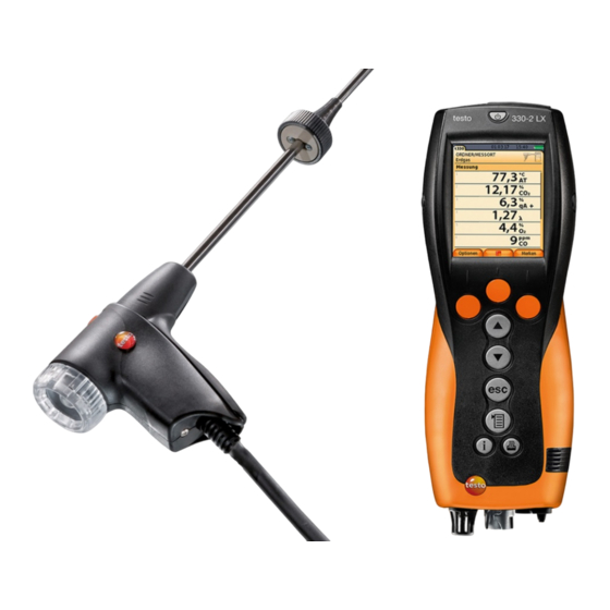
4 Product description 4.4. Modular flue gas probe 1 Removable filter chamber with window and particle filter 2 Probe handle 3 Connecting cable 4 Connector plug for measuring instrument 5 Probe module lock release 6 Probe module... -
Page 29: First Steps
3. Open the battery lock: Press the grey key and push in direction of arrow. 4. Remove the battery and insert a new rechargeable battery. Only use the Testo rechargeable battery 0515 0107! 5. Close the battery lock: Press the grey key and push against direction of arrow until the battery engages. -
Page 30: Charging Batteries
Switching the measuring instrument on has the effect of stopping battery charging and the measuring instrument is then powered via the mains unit. For longer measurements that are mains-operated, Testo recommends using a combustion air temperature probe with connecting cable. Self-heating of the instrument during mains operation may influence the combustion air temperature measurement with a mini ambient air probe. -
Page 31: Connecting Probes / Sensors
5 First steps 5.2.2. Connecting probes / sensors Probe/sensor detection at the flue gas socket is carried out continuously. New probes are recognised automatically. Connect a probe to the probe socket before switching on the measuring instrument or start sensor detection manually after changing the probe: [Options] →... -
Page 32: Switching On
5 First steps 5.2.3. Switching on > press The start screen is displayed (duration: about 5 s). If the voltage supply was interrupted for a longer period: The menu Date / Time is opened. The pressure sensors are set to zero. There is a device error: The Error Diagnosis is displayed. -
Page 33: Show Graphic
5 First steps Input editor 1. Select the value to be changed (character): [▲], [▼], [◄], [►]. 2. Accept value: [OK]. Options: > Toggle between upper / lower case characters: ← → → → Select Ι &$/ Ι : [▲], [▼] →... -
Page 34: Printing / Saving Data
5 First steps 5.2.7. Printing / saving data Data are printed out via the function key or the menu Options. Data are saved via the menu Options. The menu Options accessed via the left function key and is available in many different menus. -
Page 35: Switching Off
5 First steps 5.2.10. Switching off Unsaved measuring values will be lost when the flue gas analyser is switched off. > Press Possibly: The pump starts and the sensors are rinsed until the switch-off thresholds (O2 > 20 %, other measurement parameters <... - Page 36 5 First steps Search 1. Edit search criteria: [►] → [Edit]. 2. Select search criteria: [▲], [▼] → [OK]. Possible options: • Contact person • Address • Town/city • Postcode • Street The selected criterion is displayed. 3. Call up entry field for search text: [►] or [▼] >...
-
Page 37: Measurement Records
5 First steps Other location options: > [Options] → Edit location: make changes to an existing location. > [Options] → Copy location: make a copy of an existing location in the same address. > [Options] → Delete location: delete an existing location. Create new address: [Options] →... -
Page 38: Instrument Diagnosis
5.5. Instrument diagnosis Important operating values and instrument data are displayed. A gas path check (testo 330-2 LX) can be carried out. The status of the sensors and any device errors not yet rectified can be displayed. Calling up the function: >... -
Page 39: Using The Product
6 Using the product Using the product 6.1. Performing settings 6.1.1. Assigning the right function key The right function key can have a function from the Options menu assigned to it. The menu Options is accessed via the left function key and is available in many different menus. - Page 40 6 Using the product Display Parameter Carbon dioxide Carbon monoxide Carbon monoxide undiluted Nitrogen monoxide Nitrogen oxide λ Air ratio amCO Ambient carbon monoxide amCO2 Ambient carbon dioxide O2ref Oxygen reference Edrft external draught (micro pressure probe) E-∆P external differential pressure (micro pressure probe) qAnet Flue gas loss without consideration of the heat...
-
Page 41: Alarm Limits
6 Using the product Options: > [Options] → Number of Lines: Change the number of measuring values per display page. > [Options] → Insert Empty Lines: Insert the empty line before the selected line. > [Options] → Delete Line: Delete the selected line. >... -
Page 42: Energy Management
6 Using the product Setting date/time: 1. Select parameter: [◄], [▲], [▼] → [Edit]. 2. Set parameter: [▲], [▼] and partly [◄], [►] → [OK]. 3. Save changes: [Save]. 6.1.2.5. Energy management Automatic instrument shutdown (Auto-Off) and switching off of the display light in battery operation can be set. -
Page 43: Printer
6 Using the product 6.1.2.8. Printer The headers (lines 1-3) and the footers for the printout can be set. The printer that is used can be activated. Calling up the function: > → Instrument Settings → [OK] → Printer → [OK] Activating the printer: The printer 0554 0543 can only be selected after the... -
Page 44: Country Version
The selection of the country version influences the menu languages that can be enabled. For information concerning the assignment table, the basis for calculation and the country version, see www.testo.com/download- center. Calling up the function: >... -
Page 45: Sensor Settings
6 Using the product Changing the password: 1. [Edit]. 2. Enter the new password → [Next]. 3. [Edit]. 4. Enter the new password again to confirm → [Next]. 5. Save changes: [Finished]. 6.1.3. Sensor settings 6.1.3.1. addition The NO2 addition parameter can be set. The setting of the NO2-addition can be password protected, see Password protection, page 44. -
Page 46: Sensor Protection
6.1.3.4. Recalibration / adjustment CO and NO sensors can be recalibrated and adjusted. For recalibration / adjustment Testo recommends the use of the calibration adapter 0554 1205. If obviously unrealistic readings are displayed, the sensors should be checked (calibrated) and, if required, adjusted. -
Page 47: Fuels
Apart from the pre-configured fuels, 10 more customer specific fuels can be configured. Fuel parameter, see www.testo.com/download-center (registration required). In order to maintain the measuring accuracy of the instrument one must choose or configure the correct fuel. -
Page 48: Programs
6 Using the product Activating fuels: > Select the fuel → [OK]. The fuel is activated and the main menu is opened. Setting coefficients: 1. Select the fuel → [Coeff.]. 2. Select the coefficients: [Edit]. Possibly: > Enter the password: [Enter] →... -
Page 49: Measuring
When the instrument is switched on the measurement menu is opened and the gas sensors are zeroed. testo 330-1 LX: The flue gas probe must be in the open air during the zeroing phase! testo 330-2 LX: The flue gas probe can be in the flue gas duct even during the zeroing phase, if a separate VT- sensor is plugged in. -
Page 50: Using The Modular Flue Gas Probe
6 Using the product 6.2.1.2. Using the modular flue gas probe Checking the thermocouple The thermocouple of the flue gas probe must not lie against the probe cage. > Check before use. Bend the thermocouple back if necessary. Aligning the flue gas probe The flue gas must be able to flow freely past the thermocouple. -
Page 51: Configuring The Reading Display
6 Using the product 6.2.1.3. Configuring the reading display Only those parameters and units, which are activated in the reading display, appear in the reading display, the saved measurement protocols and the record printouts. > Before performing measurements set up the reading display in such a way, that the required parameters and units are activated, see Fehler! Verweisquelle konnte nicht gefunden werden., page Fehler! Textmarke nicht definiert.. - Page 52 330 LX. Data is transferred via Bluetooth® or via the IrDA interface. For data transfer via Bluetooth®, the testo 315 - 3 and the testo 330 - 2 LX must have this option, otherwise data is transferred via the IrDA interface.
-
Page 53: Draught-Measurement
6 Using the product Show flue gas matrix This function is only available if the measurement parameter has been activated in the readings display. Calling up the function: ✓ The flue gas function is opened. > [Options] → Flue Gas Matrix: Options >... -
Page 54: Micro Pressure Probe
6 Using the product 1. Start measurement: Draught zeroing. 2. Position the flue gas probe in the hot spot (area of the highest flue gas temperature). The display showing the maximum measured flue gas temperature max) helps when positioning the probe. The reading is displayed. -
Page 55: Bimschv (Testo 330-2 Lx)
6 Using the product 6.2.5. BImSchV (testo 330-2 LX) A qA mean value measurement can be carried out. For this purpose the mean value is determined continuously over a period of 30s, the measuring cycle takes 1s. The mean values actually valid at the corresponding time of recording are displayed. -
Page 56: Co Undiluted
2. Enter data or values → [Next] or [OK]. Determining smoke tester no. / smoke nos. / oil derivative with the smoke tester testo 308 and transferring wireless: The testo 308 must be in data transfer mode ( lights up). > [Options] → t308. -
Page 57: Differential Pressure
1. Start measurement: Pressure zeroing. 2. Connect a silicone hose to the testo 330-2 and the system to be tested. The reading is displayed. 3. Quit measurement:... -
Page 58: Differential Temperature
6 Using the product Options: > [Options] → Clipboard: Data are saved to the clipboard > [Options] → Delete clipboard: Any data saved to the clipboard is deleted. > [Options] → Save: The readings are saved in a record. > [Options] →... -
Page 59: Gas Flow
6 Using the product Performing the measurement: 1. Start measurement: The reading is displayed. 2. Quit measurement: Options: > [Options] → Clipboard: Data are saved to the clipboard. > [Options] → Delete clipboard: Any data saved to the clipboard is deleted. >... -
Page 60: Oil Flow
6 Using the product 6.2.12. Oil flow The function is only available if the chosen fuel is an oil. Calling up the function: > → Measurements → [OK] → Oil Flow → [OK]. Performing the measurement: 1. Select the parameters Oil Flow (of the oil nozzle) and Pressure... -
Page 61: Co2 Ambient
6 Using the product Performing the measurement: 1. Start measurement: The measurement starts and the measuring value is displayed graphically (trend display). An audible alarm signal is triggered when the alarm limit is reached. 2. Quit measurement: 3. Confirm the message: [OK]. Options: >... -
Page 62: Automatic Furnaces
6 Using the product > [Options] → Show Graphic: The readings are displayed in form of a line graph. > [Options] → Alarm Limit: The alarm limits menu is opened. > [Options] → Edit. Values for adjustable parameters can be edited. -
Page 63: Solid Fuel Measurement
6 Using the product Options > [Options] → Clipboard: Data are saved to the clipboard. > [Options] → Delete clipboard: Any data saved to the clipboard is deleted. > [Options] → Save: The readings are saved in a record. > [Options] →... -
Page 64: Gas Pipe Tests
6 Using the product 5. Start measurement: The stabilisation phase (minimum 2 min) progresses. After this the measuring phase starts automatically (minimum 5 min). The stabilisation phase can be interrupted early. > Press [Next]. The measuring phase starts automatically. The measuring result is displayed after the measuring phase has been completed. -
Page 65: Tightness Test 1
6 Using the product pressure adapter onto the flue gas socket and lock in place by slightly turning it clockwise (bayonet lock). Performing the measurement: ✓ The pressure socket of the instrument must be free (i.e. unpressurized, not closed). Tightness Test 1 →... -
Page 66: Tightness Test 2
6 Using the product Performing the measurement: ✓ The pressure socket of the instrument must be free (i.e. unpressurized, not closed). Tightness Test 2 → [OK]. 2. Select parameter: [▲], [▼] → [Edit]. 3. Set parameters or enter values: [▲], [▼] and partly [◄], [►]→... -
Page 67: 6.2.17.4. Leak Detection
6 Using the product > End stability time and measurement early: [Next]. The readings and Result Let By Test are displayed when measurement has been completed. [Edit] → Select test result: [▲], [▼] → [OK]. 6.2.17.4. Leak detection In gas leak detection no measurement is made, but a gas detection is performed. -
Page 68: Transferring Data
Transferring data 6.3.1. Report printer To be able to transmit data via infrared or Bluetooth interface to a Testo report printer, the printer to be used must have been activated, see Printer, page 43. Printing out data takes place via [Print] ]. -
Page 69: Maintaining The Product
7 Maintaining the product Maintaining the product 7.1. Cleaning the measuring instrument > If the housing of the measuring instrument is dirty, clean it with a damp cloth. Use distilled water, or alternatively mild solvents such as isopropanol to clean the flue gas analyzer. If using isopropanol, please refer to the instruction leaflet for the product. -
Page 70: Recalibrating / Adjusting Sensors
7 Maintaining the product Do not remove the auxiliary circuit board for the NO- sensor until immediately before installation. Do not leave the sensor without auxiliary circuit board for longer than 15 min. 5. Install new sensor / new bridge in the slot. 6. -
Page 71: Cleaning The Modular Flue Gas Probe
7 Maintaining the product 7.5. Cleaning the modular flue gas probe ✓ Disconnect the flue gas probe from the measuring instrument prior to cleaning. 1. Release the probe catch by pressing the key on the probe handle and remove the probe module. 2. - Page 72 7 Maintaining the product 2. Remove the thermocouple plug-in head from the socket using a screwdriver and pull the thermocouple out of the probe shaft. 3. Keep inserting the new thermocouple into the probe shaft until the connection head clicks into place. 4.
-
Page 73: Condensate Container
7 Maintaining the product 7.8. Condensate container The fill level of the condensate trap can be read from the markings on the condensate trap. A warning message ( , red flashing light) is displayed if the fill level in the condensate trap reaches 90 %. The fill level of the condensate trap can be read from the markings. -
Page 74: Checking / Replacing The Particle Filter
7 Maintaining the product The condensate outlet must be completely closed (marking), otherwise measuring errors could be caused by infiltrated air. 7.9. Checking / replacing the particle filter Checking the particle filter: Check the particle filter of the modular flue gas probe periodically for contamination: check visually by looking through the window of the filter chamber. -
Page 75: Tips And Assistance
> Activate printer used, see Printer, page 43. • Switch on printer. > Move printer within wireless transmission range. If we could not answer your question, please contact your dealer or Testo Customer Service. Contact data see back of this documet or website www.testo.com/service-contact. -
Page 76: Accessories And Spare Parts
8 Tips and assistance 8.2. Accessories and spare parts Printer Description Article no. Infrared high-speed printer 0554 0549 ® Bluetooth /IRDA printer, incl. Mains unit 5 V / 1.0 A 0554 0620 with micro USB cable Mains unit 5 V / 1.0 A with micro USB cable 0554 1105 Spare thermal paper for printer (6 rolls) 0554 0568... - Page 77 8 Tips and assistance Description Article no. Probe shaft module 300 mm, 1,000 °C, 0554 8764 thermocouple 1.0 mm, probe shaft diameter: 6 mm Probe shaft module 700 mm, 1,000 °C, 0554 8765 thermocouple 1.0 mm, probe shaft diameter: 6 mm Spare thermocouple for module 0554 9760, 0430 9760 0554 9762...
- Page 78 8 Tips and assistance Description Article no. CO2 ambient probe (without connecting cable) 0632 1240 Connecting cable for CO2 ambient probe, 1.5 m 0430 0143 Gas pressure set: Draught path adapter, silicone 0554 1203 hose 4 mm / 6 mm, reducing cones Differential temperature set, 2 pipe wrap probes, 0554 1204 adapter...
- Page 79 Pressure test set for gas line testing 0554 1213 ISO Calibration Certificate Flue Gas 0520 0003 For a complete list of all accessories and spare parts, please refer to the product catalogues and brochures or look up our website www.testo.com...
-
Page 80: Updating The Instrument Software
Updating the instrument software Under www.testo.com/download-center you can download the current instrument software (Firmware) for testo 330 LX (registration required). > Unplug the mains unit and switch off the testo 330 LX. 1. Hold [▲] depressed. 2. Plug in the mains unit, keep [▲]... - Page 82 0970 3343 en 02 en_DE...
Need help?
Do you have a question about the 330 LX and is the answer not in the manual?
Questions and answers