TESTO 330 Instruction Manual
Flue gas analyzer
Hide thumbs
Also See for 330:
- Instruction manual (88 pages) ,
- Update manual (8 pages) ,
- Instruction manual (78 pages)
Table of Contents
Advertisement
Quick Links
Advertisement
Table of Contents

Related Manuals for TESTO 330


Summary of Contents for TESTO 330
- Page 1 330 · Flue gas analyzer Instruction manual...
-
Page 3: Table Of Contents
1 Contents Pos: 1 /TD/Überschriften/1. Inhalt @ 0\mod_1177587817070_7011.doc @ 7061 @ 1 Contents Contents ....................3 Safety and the environment..............6 2.1. About this document ................6 2.2. Ensure safety...................7 2.3. Protecting the environment..............8 Specifications ..................9 3.1. Use ....................9 3.2. Technical data .................9 3.2.1. - Page 4 1 Contents 5.2.5. Entering data ....................26 5.2.6. Printing / saving data ..................27 5.2.7. Remembering data (clipboard) ..............28 5.2.8. Confirming an error message ................ 28 5.2.9. Switching off ....................29 5.3. Folders / measurement places............29 5.4. Protocols ..................30 5.5.
- Page 5 1 Contents 6.2.12. CO ambient....................53 6.2.13. CO2 ambient....................54 6.2.14. Automatic stokers ..................55 6.2.15. Gas pipe tests....................56 6.2.15.1. Leakage rate test................56 6.2.15.2. Main test..................57 6.2.15.3. Pretest.....................58 6.2.15.4. Leak detection .................59 6.3. Transferring data ................59 6.3.1. Protocol printer ....................59 6.3.2. PC / Pocket PC....................60 Maintaining the product ................61 7.1.
-
Page 6: Safety And The Environment
> Hand this documentation on to any subsequent users of the product. Pos: 7 /TD/Sicherheit und Umwelt/Zu diesem Dokument/Symbole und Schreibkonventionen/Symbole und Schreibkonv. [testo 330] @ 6\mod_1278662875713_7011.doc @ 64914 @ 5 Symbols and writing standards Representation Explanation Warning advice, risk level according to the signal word: Warning! Serious physical injury may occur. -
Page 7: Ensure Safety
> The objects to be measured or the measurement environment may also pose risks: Note the safety regulations valid in your area when performing the measurements. Pos: 18 /TD/Sicherheit und Umwelt/Sicherheit gewährleisten/Option Bluetooth testo 330 @ 7\mod_1281422320910_7011.doc @ 68225 @ 5 ® For products with Bluetooth... -
Page 8: Protecting The Environment
> At the end of its useful life, send the product to the separate collection for electric and electronic devices (observe local regulations) or return the product to Testo for disposal. Pos: 21 /TD/Überschriften/3. Leistungsbeschreibung @ 0\mod_1173774791554_7011.doc @ 7013 @ 1... -
Page 9: Specifications
Pos: 24 /TD/Überschriften/3.2 Technische Daten @ 0\mod_1176211088437_7011.doc @ 7033 @ 2 3.2. Technical data Pos: 25 /TD/Leistungsbeschreibung/Technische Daten/testo 330 Technische Daten/Zulassungen testo 330 (LV-spezifisch) @ 6\mod_1278665812606_7011.doc @ 65026 @ 3.2.1. Examinations and licenses As declared in the certificate of conformity, this product complies... -
Page 10: Bluetooth ® Module (Option)
The FCC demands that the user is to be informed that with any changes and modifications to the device, which have not been explicitly approved by testo AG, the right of the user to use this device will become null and void. -
Page 11: Declaration Of Conformity
3 Specifications Pos: 26 /TD/Leistungsbeschreibung/Technische Daten/testo 330 Technische Daten/Konformitätserklärung testo 330 @ 6\mod_1278667479326_7011.doc @ 65058 @ 3.2.3. Declaration of Conformity... -
Page 12: Measuring Ranges And Resolution
3 Specifications Pos: 27 /TD/Leistungsbeschreibung/Technische Daten/testo 330 Technische Daten/Messbereiche_Genauigkeiten testo330 @ 6\mod_1278672896705_7011.doc @ 65122 @ 3.2.4. Measuring ranges and resolution Parameter Measuring range Resolution 0...21 Vol.% 0.1 vol.% 0...4000 ppm 1 ppm CO, H -comp. 0...8000 ppm 1 ppm COlow 0...500 ppm... -
Page 13: Accuracy And Response Time
3 Specifications 3.2.5. Accuracy and response time Parameter Accuracy Response time ±0.2 vol.% < 20 s (t90) ±20 ppm (0...400 ppm) < 60 s (t90) ±5 % of mv (401...1000 ppm) ±10 % of mv (1001...4000 ppm) CO, H -comp. ±10 ppm or ±10 % of mv <... -
Page 14: Other Device Data
±100 ppm + 3% of mv (5001...10000 ppm) Gas leak testing < 2 s (t90) with 0632 3330 Pos: 28 /TD/Leistungsbeschreibung/Technische Daten/testo 330 Technische Daten/weitere Gerätedaten testo 330 @ 6\mod_1278676889881_7011.doc @ 65154 @ 3.2.6. Other device data Flue gas analyzer Characteristic... - Page 15 (option) Range < 10 m Warranty Measuring instrument: 48 months LL-sensors O2, CO: 48 months, Other sensors: 24 months Flue gas probe: 48 months Thermocouple: 12 months Rech. batt: 12 months Terms of warranty Terms of warranty: see website www.testo.com/warranty...
-
Page 16: Product Description
4 Product description Pos: 29 /TD/Überschriften/4. Produktbeschreibung @ 0\mod_1173774846679_7011.doc @ 7014 @ 1 Product description Pos: 30 /TD/Produktbeschreibung/Übersicht/testo 330 Übersicht @ 6\mod_1278679432401_7011.doc @ 65186 @ 4.1. Measuring instrument 4.1.1. Overview 1 Switch on/off 2 Interfaces: USB, PS2, infrared CAUTION Risk of injury from infrared beam! -
Page 17: Keypad
Function key (orange, 3x), relevant function is shown in the display Example [▲] Scroll up, increase data [▼] Scroll down, reduce data [esc] Back, cancel function Open main menu [ i ] Open instrument diagnosis menu Transmit data to the Testo protocol printer. -
Page 18: Display
4 Product description 4.1.3. Display 1 Status bar (dark gray background): • Warning symbol (only if there is an Error Service, display of Error Services in instrument diagnosis menu), otherwise: Instrument designation. • Symbol (only if data are stored in the temporary memory). -
Page 19: Device Connections
4 Product description 4.1.4. Device connections 1 Probe socket 2 Flue gas socket 3 Mains unit socket 4 Pressure socket 4.1.5. Interfaces 1 USB interface 2 PS2-interface 3 Infrared interface (IrDA) 4 Bluetooth interface (option) -
Page 20: Components
4 Product description 4.1.6. Components 1 Rech. batt. 2 Measuring gas pump 3 Slot for CO-sensor or COlow-sensor 4 Slot O2-sensor 5 Slot NO-sensor 6 Additional filter... -
Page 21: Carrying Strap (0440 0581)
4 Product description 4.1.7. Carrying strap (0440 0581) To secure the carrying strap: > Remove the sealing caps from the sides of the housing. Fix the sealing caps on the inside of the service cover: 1. Place the measuring instrument on its front. 2. -
Page 22: Modular Flue Gas Probe
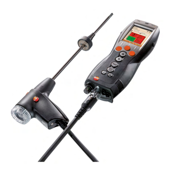
4 Product description 4.2. Modular flue gas probe 1 Removable filter chamber with window and particle filter 2 Probe handle 3 Connecting cable 4 Connector plug for measuring instrument 5 Probe module lock release 6 Probe module Pos: 31 /TD/Überschriften/5. Erste Schritte @ 0\mod_1173774895039_7011.doc @ 7015 @ 1... -
Page 23: First Steps
Pos: 34 /TD/Überschriften/5.3 Produkt kennenlernen @ 0\mod_1185342901015_7011.doc @ 7100 @ 5.2. Getting to know the product Pos: 35 /TD/Erste Schritte/testo 330/testo 330 Produkt kennenlernen Netzteil_Akkus_Batt @ 6\mod_1278932047863_7011.doc @ 65258 @ 5.2.1. Mains unit / rech. batt. If the mains unit is connected, the measuring instrument is automatically powered from the unit. -
Page 24: Charging The Rech. Batt
5 First steps 6. Attach the service cover and engage it in place. 5.2.1.2. Charging the rech. batt. The rech. batt. can only be charged at an ambient temperature of ±0...+35 °C. If the rech. batt. has been discharged completely, the charging time at room temperature is approx. -
Page 25: Connecting Probes / Sensors
5 First steps Pos: 36 /TD/Erste Schritte/testo 330/testo 330 Produkt kennenlernen Sonden/Fühler anschließen @ 6\mod_1278934157318_7011.doc @ 65290 @ 5.2.2. Connecting probes / sensors Sensor detection at the sensor socket takes place during the activation process. ✓ Sensors that are required must always be connected before the... -
Page 26: Switching On
5 First steps Pos: 37 /TD/Erste Schritte/testo 330/testo 330 Produkt kennenlernen Basisfunktionen (LV-spezifisch) @ 6\mod_1278935326903_7011.doc @ 65322 @ 5.2.3. Switching on > press The start screen is displayed (duration: about 5 s). If the voltage supply was interrupted for a longer period: The menu Date / Time is opened. -
Page 27: Printing / Saving Data
5 First steps 5. Repeat steps 1 and 4 as required. 6. Save the entry: [Finished]. Input editor 1. Select the value to be changed (character): [▲], [▼], [◄], [►]. 2. Accept value: [OK]. Options: > Toggle between upper / lower case characters: ←... -
Page 28: Remembering Data (Clipboard)
5 First steps Only meas. views, which have a display field in the measurement view assigned, will be saved / printed out. The measurement data can be printed out parallel to the saving process, while a measurement program is running. To be able to transmit data via infrared or Bluetooth interface to a protocol printer, the printer to be used must have been enabled, see Enabling the printer:, page 37. -
Page 29: Switching Off
< 50 ppm) are reached. The maximal rinsing period is 3 minutes. The measuring instrument switches off. Pos: 38 /TD/Erste Schritte/testo 330/testo 330 Produkt kennenlernen Ordner_Messorte @ 6\mod_1278942335615_7011.doc @ 65354 @ 5.3. Folders / measurement places All readings can be saved under the currently active site. Meas. -
Page 30: Protocols
Folder: Delete an existing folder, including the sites created therein. • Delete all Folders: Delete all existing folders, including the sites created therein. Pos: 39 /TD/Erste Schritte/testo 330/testo 330 Produkt kennenlernen Protokolle @ 6\mod_1279004185634_7011.doc @ 65385 @ 5.4. Protocols Calling up the function: > →... -
Page 31: Instrument Diagnosis
→ Delete all Measurements: Delete all saved protocols for a site. Pos: 40 /TD/Erste Schritte/testo 330/testo 330 Produkt kennenlernen Gerätediagnose @ 6\mod_1279004297026_7011.doc @ 65416 @ 5.5. Instrument diagnosis Important operating data and instrument data are displayed. A gas path check (testo 330-2 LL) can be carried out. The status of the sensors and any Error Services not yet rectified can be displayed. - Page 32 5 First steps Viewing sensor diagnosis: 1. > Sensor Diagnosis → [OK]. 2. Select sensor. [▲], [▼]. The status of the sensor is indicated by a lamp. A sensor is able to recover. It is therefore possible that the sensor status indication changes from yellow to green or from red to yellow.
-
Page 33: Using The Product
3. Assign the selected function to the right function key. Press Pos: 44 /TD/Produkt verwenden/testo 350 neu/testo 350 Geräteeinstellungen CU/testo 350 Geräteeinstellungen_Ueberschrift @ 5\mod_1266322627982_7011.doc @ 58685 @ 3 6.1.2. Device settings Pos: 45 /TD/Produkt verwenden/testo 330/testo 330 Geräteeinstellungen aufrufen @ 6\mod_1279008333499_7011.doc @ 65448 @ It is assumed that the contents of the chapter First steps (see First steps, page 23) are known. - Page 34 6 Using the product Display Measurement parameter Tsensor Instrument temperature Pump Pumping capacity Oxygen Carbon dioxide η+ Efficiency net under due consideration of the heat value range Carbon monoxide Carbon monoxide undiluted Nitrogen monoxide Nitrogen oxide ExAir Air ratio COamb Ambient carbon monoxide CO2a Ambient carbon dioxide...
-
Page 35: Alarm Thresholds
→ Factory Setting: Reset the measurement view to factory setting Pos: 47 /TD/Produkt verwenden/testo 330/testo 330 Alarschwellen @ 6\mod_1279021018511_7011.doc @ 65512 @ 6.1.2.2. Alarm thresholds Alarm thresholds can be set for several display parameters. An audible alarm signal is triggered when the alarm limit is reached. -
Page 36: Date / Time
[◄], [►] → [OK]. 3. Save changes: [Save]. Pos: 50 /TD/Produkt verwenden/testo 330/Testo 330 Energieverwaltung @ 6\mod_1279023810346_7011.doc @ 65607 @ 6.1.2.5. Energy management Auto-Off and switching off of the display light in rech. batt. operation can be set. -
Page 37: Bluetooth
2. Select function: [▲], [▼] → [Edit]. 3. Enter data → [Next]. 4. Save the entry: [Finished]. Pos: 53 /TD/Produkt verwenden/testo 330/testo 330 Bluetooth @ 6\mod_1279026530745_7011.doc @ 65703 @ 6.1.2.8. Bluetooth ® This menu is only available if the instrument is equipped with Bluetooth option. -
Page 38: Country Version
→ [OK]. 2. Confirm confirmation request: → [OK] The system is restarted. Pos: 56 /TD/Produkt verwenden/testo 330/testo 330 Passwortschutz @ 6\mod_1279028157194_7011.doc @ 65831 @ 6.1.2.11. Password protection The password protection is only valid for functions identified by the following symbol: Password protection can be enabled / disabled, the password can be changed. -
Page 39: Sensor Settings
2. Enter the new password → [Next]. 3. [Edit]. 4. Enter the new password again to confirm → [Next]. 5. Save changes: [Finished]. Pos: 57 /TD/Produkt verwenden/testo 330/testo 330 Sensoreinstellungen @ 6\mod_1279095713244_7011.doc @ 65865 @ 6.1.3. Sensor settings 6.1.3.1. addition The NO2 addition parameter can be set. -
Page 40: Sensor Protection
6.1.3.4. Recalibration / adjustment CO and NO sensors can be recalibrated and adjusted. For recalibration / adjustment Testo recommends the use of the calibration adapter 0554 1205. If obviously unrealistic readings are displayed, the sensors should be checked (calibrated) and, if required, adjusted. -
Page 41: Fuels
7. Accept the val. nom. once the act. val. is stable (adjustment): [OK]. -or- Abort (no adjustment): [esc]. 8. Save changes: [Finished]. Pos: 58 /TD/Produkt verwenden/testo 330/testo 330 Brennstoffe @ 6\mod_1279096803274_7011.doc @ 65897 @ 6.1.4. Fuels The fuel can be selected. The fuel-specific coefficients and set limits can be set. -
Page 42: Programs
Setting set limits: 1. Select set limit → [Edit]. 2. Set data → [OK]. 3. Save changes: [Finished]. Pos: 59 /TD/Produkt verwenden/testo 330/testo 330 Programme @ 6\mod_1279096840212_7011.doc @ 65929 @ 6.1.5. Programs Five measuring programs for different measurement types can be configured and enabled. -
Page 43: Measuring
Pos: 60 /TD/Überschriften/6.3 Messungen durchführen @ 0\mod_1184584650078_7011.doc @ 7098 @ 2 6.2. Measuring Pos: 61 /TD/Produkt verwenden/testo 330/testo 330 Messung vorbereiten @ 6\mod_1279108120992_7011.doc @ 65993 @ 6.2.1. Preparing for measurement It is assumed that the contents of the chapter First steps (see First steps, page 23) are known. -
Page 44: Using The Modular Flue Gas Probe
Draft / pressure zeroing The pressure sensors are zeroed when a pressure measuring function is called up. testo 330-1 LL: The flue gas probe must be in the open air during the zeroing phase / the instrument must not be pressurized during zeroing! -
Page 45: Configuring The Measurement View
Before carrying out measurements, the measurement location and the fuel must be correctly selected, see Folders / measurement places, page 29 and Fuels, page 41. Pos: 62 /TD/Produkt verwenden/testo 330/testo 330 Abgasmessung @ 6\mod_1279108000429_7011.doc @ 65961 @ 6.2.2. Flue gas Calling up the function: →... - Page 46 6 Using the product > [Options] → Flue Gas Matrix: The meas. views are displayed as flue gas matrix, see below. > [Options] → Number of Lines: Change the number of meas. views per display page. > [Options] → Reset to Zero: The gas sensors are set to zero.
-
Page 47: Draft-Measurement
(max. 4) can be displayed ( ) or hidden ( > [Options] → Measurement View: (This function is not available during a measurement): The measurement view menu is opened. Pos: 64 /TD/Produkt verwenden/testo 330/testo 330_Feinstdrucksonde (Landesversion ungleich DE) @ 7\mod_1282550716574_7011.doc @ 69485 @... -
Page 48: Micro Pressure Probe
[Options] → Save: The meas. views are saved in a protocol. > [Options] → Show Graphic: The meas. views are displayed in form of a line graph. Pos: 66 /TD/Produkt verwenden/testo 330/teto 330 Rußzahl/WTT (LV-spezifisch!) @ 6\mod_1279178971921_7011.doc @ 66185 @... -
Page 49: Smoke No. / Hct
→ Clipboard: Data are saved to the clipboard: > [Options] → Save: The meas. views are saved in a protocol. > [Options] → Reset values: The entered data are deleted. Pos: 67 /TD/Produkt verwenden/testo 330/testo 330 Differenzdruckmessung @ 6\mod_1279181106594_7011.doc @ 66217 @... -
Page 50: Differential Pressure
1. Start measurement: Pressure zeroing. 2. Pressurize the system. testo 330-2, Program active (see Programs page 42): The pressure socket of the instrument must be free (i.e. unpressurized, not closed) while a measurement program is running. -
Page 51: Differential Temperature
6 Using the product Pos: 68 /TD/Produkt verwenden/testo 330/testo 330 Diff_Temperaturmessung @ 6\mod_1279181201625_7011.doc @ 66249 @ 6.2.8. Differential temperature ✓ The differential temperature set (0554 1204) must be connected. Calling up the function: > → Measurements → [OK] → Differential Temperature→... -
Page 52: Flowrate
Unit: The unit for the flowrate can be changed (m3 > l l > m3). Pos: 71 /TD/Produkt verwenden/testo 330/testo 330 Öldurchsatz @ 6\mod_1279183991201_7011.doc @ 66345 @ 6.2.11. Oil flow The function is only available if the chosen fuel is an oil. Calling up the function: >... -
Page 53: Co Ambient
Unit: The unit for the oil flow can be changed (kg/h > gal/h gal/h > kg/h). Pos: 72 /TD/Produkt verwenden/testo 330/testo 330 CO-Umgebung @ 6\mod_1279194419538_7011.doc @ 66409 @ 6.2.12. CO ambient ✓ An ambient CO probe (recommended) or a flue gas probe must be connected. -
Page 54: Co2 Ambient
6 Using the product Pos: 73 /TD/Produkt verwenden/testo 330/testo 330 CO2-Umgebung @ 6\mod_1279194467663_7011.doc @ 66441 @ 6.2.13. CO2 ambient ✓ An ambient CO2 probe (0632 1240) must be connected. In order to obtain correct meas. views, it is imperative to enter the prevailing abs. -
Page 55: Automatic Stokers
6 Using the product 6.2.14. Automatic stokers With the help of the readout adapter for automatic stokers (0554 1206) status data and error messages can be read out of compatible automatic stokers, see also documentation on readout adapter. The range of data which can be read out depends on the type of the automatic stoker. -
Page 56: Gas Pipe Tests
The fault that has occurred last is at position 1 in the error list. > [Options] → Fault: Display of faults. Pos: 75 /TD/Produkt verwenden/testo 330/testo 330 Gasleitungsprüfungen @ 6\mod_1279199318613_7011.doc @ 66505 @ 6.2.15. Gas pipe tests Calling up the function: >... -
Page 57: Main Test
6 Using the product 3. Set parameters or enter data: [▲], [▼] and partly [◄], [►] → [OK]. 4. Pressurize the system. 5. Start measurement: The stability time will run. After this the measurement phase starts automatically. > End stability time and measurement early: [Next]. The readings are displayed when measurement has been completed. -
Page 58: Pretest
6 Using the product 6. Start measurement: The stability time will run. After this the measuring phase starts automatically. > End stability time and measurement early: [Next]. The readings and Result Let By Test are displayed when measurement has been completed. [Edit] →... -
Page 59: Leak Detection
→ Zeroing Probe: Perform zeroing. 2. End detection: Pos: 76 /TD/Produkt verwenden/testo 330/testo 330 Überschrift Daten übertragen @ 6\mod_1279258550805_7011.doc @ 66605 @ 2 6.3. Transferring data Pos: 77 /TD/Produkt verwenden/testo 330/testo 330 Daten übertragen @ 6\mod_1279258680964_7011.doc @ 66636 @ 6.3.1. -
Page 60: Pc / Pocket Pc
6 Using the product 6.3.2. PC / Pocket PC ® Data transfer to a PC can take place via USB, IrDA or Bluetooth ® Data transfer to a Pocket PC can take place via IrDA or Bluetooth You must also refer to the documentation that comes with the software. -
Page 61: Maintaining The Product
7 Maintaining the product Maintaining the product Pos: 79 /TD/Produkt instand halten/testo 330/testo 330 Instandhaltung_Messgerät reinigen @ 6\mod_1279260289656_7011.doc @ 66701 @ 7.1. Cleaning the measuring instrument > If the housing of the measuring instrument is dirty, clean it with a damp cloth. Do not use any aggressive cleaning agents or solvents! Mild household cleaning agents and soap suds may be used. -
Page 62: Recalibrating / Adjusting Sensors
3. Loosen the additional filter from the hose connection. 4 Plug the new filter (0133 0010) into the hose connection. 5. Attach the service cover and engage it in place. Pos: 82 /TD/Produkt instand halten/testo 350 neu/testo 350 Instandhaltung Abgassonde reinigen @ 6\mod_1270039302035_7011.doc @ 60689 @... -
Page 63: Cleaning The Modular Flue Gas Probe
(see illustration). Do not use a brush! 3. Fit a new probe module on the handle and engage in place. Pos: 83 /TD/Produkt instand halten/testo 330/testo 330 Sondenmodul wechseln @ 6\mod_1279263131873_7011.doc @ 66829 @ 7.6. Replacing the probe module ✓... -
Page 64: Changing The Thermocouple
3. Keep inserting the new thermocouple into the probe shaft until the connection head clicks into place. 4. Fit a new probe module on the handle and engage in place. Pos: 85 /TD/Produkt instand halten/testo 330/testo 330_Instandhaltung Kondensatbehälter @ 6\mod_1279263636301_7011.doc @ 66893 @ 7.8. Condensate container The fill level of the condensate trap can be read from the markings on the condensate trap. -
Page 65: Checking / Replacing The Particle Filter
The condensate outlet must be completely closed (marking), otherwise measuring errors could be caused by infiltrated air. Pos: 86 /TD/Produkt instand halten/testo 330/testo 330 Instandhaltung Partikelfilter prüfen @ 6\mod_1279265518333_7011.doc @ 66965 @ 7.9. Checking / replacing the particle filter Checking the particle filter:... - Page 66 7 Maintaining the product 1. Open the filter chamber: Turn gently anti-clockwise. 2. Remove the filter plate and replace it with a new one (0554 3385). 3. Attach the filter chamber and lock it Turn gently clockwise. Pos: 87 /TD/Überschriften/8. Tipps und Hilfe @ 0\mod_1173789887985_7011.doc @ 7024 @ 1...
-
Page 67: Tips And Assistance
Pos: 88 /TD/Überschriften/8.1 Fragen und Antworten @ 0\mod_1177402017078_7011.doc @ 7050 @ 2 8.1. Questions and answers Pos: 89 /TD/Tipps und Hilfe/Fragen und Antworten/testo 330 Fragen und Anworten @ 6\mod_1279266547844_7011.doc @ 66997 @ Question Possible causes / solution Rech. batt. low >... -
Page 68: Accessories And Spare Parts
8 Tips and assistance Pos: 90 /TD/Überschriften/8.2 Zubehör und Ersatzteile @ 0\mod_1177402058734_7011.doc @ 7051 @ 2 8.2. Accessories and spare parts Pos: 91 /TD/Tipps und Hilfe/Zubehör und Ersatzteile/testo 330 Zuberhör_Ersatzteile @ 6\mod_1279267635925_7011.doc @ 67029 @ 555555555 Printer Description Article no. - Page 69 8 Tips and assistance Description Article no. Probe shaft module 700 mm, 1,000 °C, 0554 8765 thermocouple 1.0 mm, probe shaft diameter: 6 mm Spare thermocouple for module 0554 9760, 0430 9760 0554 9762 Spare thermocouple for module 0554 9761, 0430 9761 0554 9763 Spare thermocouple for module 0554 8764...
- Page 70 8 Tips and assistance Description Article no. Ambient CO probe 0632 3331 CO2 ambient probe (without connecting cable) 0632 1240 Connecting cable for CO2 ambient probe, 1.5 m 0430 0143 Gas pressure set: Draft path adapter, silicone hose 0554 1203 4 mm / 6 mm, reducing cones Differential temperature set, 2 pipe wrap probes, 0554 1204...
- Page 71 0520 0003 For a complete list of all accessories and spare parts, please refer to the product catalogs and brochures or look up our website www.testo.com Pos: 92 /TD/Tipps und Hilfe/testo 330 Instandhaltung Update Firmware @ 6\mod_1279805277750_7011.doc @ 67295 @...
-
Page 72: Updating The Instrument Software
Updating the instrument software Under www.testo.com/download-center you can download the current instrument software (Firmware) for testo 330 (registration required). > Unplug the mains unit and switch off the testo 330. 1. Hold [▲] depressed. 2. Plug in the mains unit, keep [▲]... - Page 76 0970 3319 en-US 02 V01.01 en-US_US...
Need help?
Do you have a question about the 330 and is the answer not in the manual?
Questions and answers