Table of Contents
Advertisement
Quick Links
Advertisement
Table of Contents

Related Manuals for TESTO 335


Summary of Contents for TESTO 335
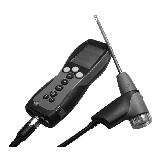
- Page 1 335 Flue gas analyser Instruction manual...
-
Page 2: General Notes
Please read this documentation through carefully and familiarise yourself with the opera- tion of the product before putting it to use. Keep this document to hand so that you can refer to it when necessary. This document describes the country-specific version GB of the testo 335 measuring instrument. Identification... - Page 3 General notes 3 Short form This document uses a short form for describing steps (e.g. calling up a function). Example: Calling up the function Flue gas Short form: Measurements Flue gas Steps required: 1 Open the Main menu: 2 Select menu: Measurements 3 Confirm selection:...
-
Page 4: Table Of Contents
Content Content See also Functional overview , p. 60. General notes ..................2 Content ....................4 Safety advice..................7 Intended purpose ..................8 Product description ................9 Measuring instrument ..............9 C.1.1 Overview ..................9 C.1.2 Keypad ..................10 C.1.3 Display..................10 C.1.4 Instrument connections ............11 C.1.5 Interfaces ..................12 C.1.6 Components ................12 C.1.7... - Page 5 Content 5 Basic operating steps ..............20 E.4.1 Switching the measuring instrument on ........20 E.4.2 Calling up the function ............20 E.4.3 Entering values ................21 E.4.4 Printing data ................22 E.4.5 Saving data ................22 E.4.6 Confirming an error message ............22 E.4.7 Switching the measuring instrument off ........22 Memory ..................23 E.5.1 Folders..................23...
- Page 6 Content Transferring data ..................46 Protocol printer ................46 PC / Pocket PC ................46 Care and maintenance ................47 Cleaning the measuring instrument ..........47 Replacing measuring cells ............47 Recalibrating measuring cells............48 Replacing additional filter ..............48 Cleaning the modular flue gas probe ..........49 Replacing probe preliminary filter ..........49 Replacing thermocouple ..............49 Questions and answers ..............50 Technical data ..................51...
-
Page 7: Safety Advice
Follow the prescribed steps exactly. For safety reasons, use only original spare parts from Testo. Any additional work must only be carried out by authorised personnel. Testo will otherwise refuse to accept responsibility for the proper functioning of the measuring instrument after repair and for the validity of certifications. -
Page 8: Intended Purpose
B. Intended purpose This chapter describes the areas of application for which the measuring instrument is intended. The testo 335 is a handheld measuring instrument used in professional flue gas analysis for: · Engineers servicing/monitoring industrial combustion plants (process systems, power stations) ·... -
Page 9: Product Description
C. Product description C.1 Measuring instrument C. Product description This chapter provides an overview of the individual components of the product. C.1 Measuring instrument C.1.1 Overview On/Off button Placeholder: Interfaces: USB, PS2, infrared Pbersicht.tif Do not point infrared beam at people's eyes! Condensate trap (on rear) Fixing eyelet for carrying strap (left and... -
Page 10: Keypad
C. Product description C.1 Measuring instrument C.1.2 Keypad Functions Switch measuring instrument on/off Function key (orange, 3x), relevant function is shown on the display Scroll up, increase value Scroll down, reduce value Back, cancel function Open Main menu: press briefly (changed settigs are stored, measurement values are carried over into the menu Flue gas);... -
Page 11: Instrument Connections
C. Product description C.1 Measuring instrument Settings view Active menu Function fields for entering commands Scroll bar Selection field for adjustable values: The selected value is shown with a grey background. Unavailable values are written in grey type. Function keys for entering commands Measuring view Active menu, depending on the selected function: Additional information (e.g. -
Page 12: Interfaces
USB interface: connection to PC PS2 interface: Adapter for automatic furnaces Infrared interface (IrDA): connection to Testo-printers / Pocket PC C.1.6 Components Rechargeable battery Measuring gas pump Measuring cells - slot 2: CO, NO2, SO2 Measuring cells - slot 1: O2... -
Page 13: Carrying Strap
C. Product description C.1 Measuring instrument C.1.7 Carrying strap To secure the carrying strap: 1 Remove sealing caps from the sides of the Placeholder: housing. Halterung_Verschluss- Fix s s ealing c c aps o o n t t he i i nside o o f t t he s s ervice c c over: stopfen.tif 1 Place the measuring instrument on its front. -
Page 14: Commissioning
D. Commissioning D. Commissioning This chapter describes the steps required to commission the product. Remove the protective film from the display. The measuring instrument is supplied with a rechargeable battery already fitted. Charge the rechargeable battery up fully before using the measuring instrument (see Charging batteries , p. -
Page 15: Operation
Press the orange key and push in the direction of the arrow. 4 Remove the rechargeable battery and insert a new one. Use only Testo 0515 0100 rechargeable bat- teries! 5 Close the rechargeable battery compartment: Press the orange key and push against the direc- tion of the arrow until the rechargeable battery engages. -
Page 16: Charging Batteries
E. Operation E.1 Mains unit/rechargeable battery E.1.2 Charging batteries The rechargeable battery can only be charged at an ambient temperature of ±0...+35°C. If the rechargeable battery has discharged completely, the charging time at room tem- perature is approx. 5-6 hrs. Charging in the measuring instrument The measuring instrument must be switched off. -
Page 17: Probes/Sensors
B. Operation E.2 Probes/sensors E.2 Probes/sensors E.2.1 Connecting probes/sensors Sensor s s ocket: Sensor detection is carried out at the sensor socket during the activation process: Always connect the sensors you need to the measuring instrument before switching it on or switch the device on and then off again after a change of sensor so that the correct sensor data are read into the measuring instrument. -
Page 18: Replacing The Probe Module
E. Operation E.2 Probes/sensors E.2.2 Replacing the probe module 1 Press the key on the top of the probe handle and remove the probe module. 2 Fit a new probe module and engage it in place. E.3 Regular care E.3.1 Condensate trap The fill level of the condensate trap can be read from the markings on the trap. -
Page 19: Checking/Replacing The Particle Filter
E. Operation E.3 Regular care E.3.2 Checking/replacing the particle filter Checking the particle filter: Check the particle filter of the modular flue gas probe for contamination at regular intervals: Check visually by looking through the window of the filter chamber. Replace the filter if there are signs of contamination Replacing the particle filter: The filter chamber may contain condensate... -
Page 20: Basic Operating Steps
E. Operation E.4 Basic operating steps E.4 Basic operating steps E.4.1 Switching the measuring instrument on - The start screen is displayed (for about 5 s). - Display light is switched on for 10 s. Option: To go directly to a measurement while the start screen is being displayed, press the function key for the desired measurement. -
Page 21: Entering Values
E. Operation E.4 Basic operating steps E.4.3 Entering values Some functions require values (numbers, units, characters) to be entered. Depending on the function that is selected, the values are entered via either a list field or an input editor. List field 1 Select the value to be changed (number, unit): 2 Adjust the value: 3 Repeat steps 1 and 2 as required. -
Page 22: Printing Data
E. Operation E.4 Basic operating steps E.4.4 Printing data Data are printed out via the function key . The function is only available if a print- Print out is possible. If data are to be transferred to a protocol printer via the infrared interface, the printer that is to be used must be activated, see Printer , p. -
Page 23: Memory
E. Operation E.5 Memory E.5 Memory All readings are allocated to the location that is activated at the time and can be saved in the Flue gas menus. Unsaved readings are lost when the measuring instrument is switched off. Folders and locations can be created (max. 100 folders, max. 10 locations per folder), edited and activated and measurement protocols can be printed. -
Page 24: Location
E. Operation E.5 Memory E.5.2 Location Creating a new location: A location is always created in a folder. 1 Select the folder New location 2 Select the Location name Change 3 Enter values OK Save input 4 Repeat steps 2 and 3 for the other criteria accordingly. OK Go to measurement OK To location Ordering the locations list:... - Page 25 E. Operation E.5 Memory For all instruments: The parameters (ambient air temperature), (ambient air humidity) Temp./amb. Hum/amb. (ambient air dew point) influence calculation of the qA (Flue gas loss) Dew p./amb. and DP (Flue gas dew point temperature). The parameters should be set to the factory settings for all standard applications (Temp./amb.: 20.0 °C, Hum/amb.: 80.0 %, Dew p./amb.: 16.4 °C).
-
Page 26: Protocols
E. Operation E.5 Memory E.5.3 Protocols Printing/deleting all protocols : Select the folder Select a location Data - The saved protocols are displayed. Protocols of measurement programs are marked with a vertical line and the number of individual measurements (e.g.. ), for more |245 than 999 measurements dots are used (... -
Page 27: Instrument Diagnosis
E. Operation E.6 Instrument diagnosis E.6 Instrument diagnosis Important operating values and instrument data are displayed. A gas path check can be carried out. The status of the measuring cells and any device errors not yet rectified can be displayed. Calling up the function: Inst’... -
Page 28: Configuration
F. Configuration F.1 Instrument settings Configuration This chapter describes the possible steps for adapting the product to the particular measurement task or the requirements of the user. Familiarity with the contents of the chapter Operation (see p. 15) is assumed. Instrument settings F.1.1 Display edit The parameters/units and the display representation (number of readings displayed per... -
Page 29: Printer
F. Configuration F.1 Instrument settings Calling up the function: Inst’ settings Display edit Setting the display representation: Select 4 values on disp large 8 values on disp small Changing parameters and units: 1 Select the display position. Options: To insert a space: Space To delete a parameter: Select parameter... -
Page 30: Start Keys Edit
F. Configuration F.1 Instrument settings F.1.3 Start keys edit The assignment of the function keys depends on the function that is selected. Only the function keys in the start screen (shown when the measuring instrument is switched on) can be assigned any function from the menu. -
Page 31: Date / Time
F. Configuration F.1 Instrument settings F.1.5 Date / Time The date and the time can be set. Calling up the function: Inst’ settings Date/Time Setting the date/time: Select Set the values Time Date Change Saving settings: OK Save input F.1.6 Language The menu language can be set. -
Page 32: Sensor Settings
F. Configuration F.2 Sensor settings Sensor settings It is possible to set an NO addition and thresholds for activating sensor protection (dilu- tion/disconnect). The actual calibration data and the status of the measuring cells can be displayed. Recalibration can be carried out. Calling up the function: Sensor settings Setting the NO2 addition:... - Page 33 F. Configuration F.2 Sensor settings Sensor protection 2 Select the parameter. Option: Reset selected parameter to default value: Deflt Set the values Change 4 Repeat steps 2 and 3 for the other parameters accordingly. Saving settings: OK Save input Displaying actual calibration data/cell status: Calibrationdata Options: To change between the actual calibration data of the individual measuring cells:...
- Page 34 · Maximum overpressure of the test gas: 30 hPa (recommended: unpressurised via bypass) · Charge the test gas for at least 3 min Recommended test gas concentrations and compositions are given in Testo's field guide to test gases. Recalibration - Possibly:Gas zeroing (30 s).
-
Page 35: Fuels
F. Configuration F.3 Fuels 4 Start calibration: Start If the parameter of the measuring cell inserted in slot 2 has been selected: - You will receive a query as to whether dilution should be initialised. Start recalibration of parameter: Start Start recalibration of dilution: Start 5 Accept the nominal value as soon as the actual value is stable:... -
Page 36: Measuring
G. Measuring G.1 Preparing measurements G. Measuring This chapter describes the measuring tasks that can be carried out with the product. Familiarity with the contents of the chapter Operation (see p. 15) is assumed. G.1 Preparing measurements G.1.1 Zeroing phases Measuring the ambient air temperature (AT) If no ambient air temperature sensor is connected, the temperature measured by the thermocouple of the flue gas probe during the zeroing phase is used as the ambient air... -
Page 37: Using The Modular Flue Gas Probe
G. Measuring G.1 Preparing measurements G.1.2 Using the modular flue gas probe Checking the thermocouple The thermocouple of the flue gas probe must not lie against the probe cage. Check before use. Bend the thermocouple back if necessary. Aligning the flue gas probe The flue gas must be able to flow freely past the thermocouple. -
Page 38: Measurements
G. Measuring G.2 Measurements G.2 Measurements G.2.1 Flue gas, Flue gas + m/s, Flue gas + ∆p2 Flue gas + ∆ ∆ p2 menus are only available on instruments with the Flue gas + m/s "Pressure/flow speed measurement" option. The flue gas menus are the central measurement menus in which - in addition to the readings measured with this function - the readings of all measurements carried out are displayed (if this is selected in the menu). -
Page 39: Program
G. Measuring G.2 Measurements For the functions Flue gas + ∆ ∆ p2 Flue gas + m/s Depressurise the pressure sensor and carry out pressure zeroing with V = 0 If n n o f f uel h h as y y et b b een s s elected: Select the fuel Measuring: 1 Start measuring:... -
Page 40: Draught
G. Measuring G.2 Measurements Running a measuring program: 1 Select the program Start 2 Select (only available if gas zeroing has already been carried out) Start without zeroing and start the program with Start with zeroing - If selected: Gas zeroing (32 s). - Stabilisation phase (60 s). -
Page 41: Smoke# /Hct
G. Measuring G.2 Measurements G.2.4 Smoke# /HCT Calling up the function: Measurements Smoke#/HCT Entering the smoke tester no./smoke #/oil derivative: The function is only available if the chosen fuel is an oil. Enter the tester number Change Sm. tester no. Enter the value Smoke # 1 Change... -
Page 42: Oil Flow Rate
G. Measuring G.2 Measurements G.2.6 Oil flow rate function is only available if the activated fuel is an oil. Oil flow rate Calling up the function: Measurements Oil flow rate Measuring: 1 Enter the flow rate: Enter the value Flowrate Change 2 Enter the oil pressure: Enter the value... -
Page 43: G.2.8 ∆P2
G. Measuring G.2 Measurements Option: To print the reading: Print 4 Accept the reading: - The menu is opened. Measurements G.2.8 ∆p2 ∆ ∆ p2 function is only available on instruments with the "Pressure/flow speed meas- urement" option. Do not measure for longer than 5 min, as the drift of the pressure sensor means that the readings could be outside the tolerance limits. -
Page 44: Burner Control
G. Measuring G.2 Measurements G.2.9 Burner control With the help of the readout adapter for automatic furnaces (0554 1206), status data and malfunction reports can be read out from compatible automatic furnaces, see also documentation for readout adapter. The range of data which can be read out is depend- ent on the automatic furnace type. - Page 45 G. Measuring G.2 Measurements Reading out failure store: Automatic furnaces are equipped with circular buffer memories, i.e. failure reports are overwritten when the failure store is full.. The last failure occurring is at position 1 in the failure list. Failure Option: Scroll through failure list: Taking readings over into the menu Flue Gas:...
-
Page 46: Transferring Data
H. Transferring data H.1 Protocol printer If data are to be transferred to a Testo protocol printer via the infrared interface, the printer that is to be used must be activated, see Printer , p. 29. Data are printed out via the function key . -
Page 47: Care And Maintenance
A slot bridge (0192 1552) must be inserted in slots which do not have a measuring cell. Used measuring cells must be disposed of as special waste! Retrofitted measuring cells: The enclosed cell heating unit is not required for testo 335. The measuring instrument must be switched off. -
Page 48: Recalibrating Measuring Cells
I. Care and maintenance I.2 Recalibrating measurimg cells 5 Insert a new measuring cell/bridge in the slot. 6 Attach tube connections to the measuring cell/bridge. 7 Attach the service cover and engage it in place. After replacing an O2 measuring cell, wait 60 min before using the instrument again. If retrofitting a measuring cell, you must activate the relevant measuring parameter and unit, see Display edit , p. -
Page 49: Cleaning The Modular Flue Gas Probe
I. Care and maintenance I.5 Cleaning the modular flue gas probe Cleaning the modular flue gas probe Detach the flue gas probe from the measuring instrument before cleaning. 1 Release the probe catch by pressing the key on the probe handle and remove the probe module. Probe shafts with preliminary filter: Unscrew the preliminary filter. -
Page 50: Questions And Answers
Ensure that gas output is free Pump flow rate to high If we could not answer your question, please contact your dealer or Testo Customer Service. Contact details can be found on the guarantee card or on the Internet under... -
Page 51: Technical Data
K. Technical data K.1 Standards and tests K. Technical data K.1 Standards and tests · As declared in the certificate of conformity, this product complies with Directive 89/336/EEC. · This product is TÜV approved to EN 50379 part 2, exception: SO2 and NO2 parame- ters are not tested, recalibration is not blocke d. - Page 52 K. Technical data K.2 Measuring ranges and accuracies Parameter Measuring range Accuracy Resolution Pabs 600...1150hPa ±10hPa 1hPa Temperature (NiCrNi) -40...1200°C ±0.5°C at 0.0...100.0°C 0.1°C at -40.0...999.9°C depends ±0.5% of reading in rest of range 1°C at 1000°C...1200°C on probe Temperature (PtRhPt)-40...1600°C ±1°C at 0.0...200.0°C 1°C...
-
Page 53: Other Instrument Data
>6 h (pump on, display light off, 20 °C ambient temperature) Battery charge time approx. 5-6h Guarantee (according to Measuring instrument: 24 months Testo guarantee conditions) Measuring cells: 12 months, O2 measuring cell: 18 months Flue gas probe: 24 months Thermocouple: 12 months Battery: 12 months... -
Page 54: Principles Of Calculation
K. Technical data K.4 Principles of calculation K.4 Principles of calculation K.4.1 Fuel parameters Fuel -Bezug AGtrMin LMin Natural gas 0.660 0.009 11.9 Vol.% 3 Vol.% 8.36 9.12 Light oil 0.680 0.007 15.4 Vol.% 3 Vol.% 10.53 11.26 Heavy oil 0.806 0.000 15.9 Vol.%... - Page 55 K. Technical data K.4 Principles of calculation η η = 100 - qA E E f f f f i i c c i i e e n n c c y y : : Calculated flue gas loss AGtrMin A A i i r r r r a a t t i i o o : : λ...
- Page 56 K. Technical data K.4 Principles of calculation Mass flow: M M a a s s s s f f l l o o w w C C O O : : MCO = CO [kg/h] [ppm] x F x 1.25 [kg/m ] x Z M M a a s s s s f f l l o o w w N N O O = NO...
-
Page 57: Recommended Rinsing Times
K. Technical data K.5 Recommended rinsing times K.5 Recommended rinsing times Recommended rinsing times in measurements with high concentrations and longer measurements: Rinse instrument: Expose probe to fresh air and start flue gas analysis Parameter Concentration [ppm] Measurement duration [min] Recommended rinsing time [min] 1000 2000... -
Page 58: Accessories/Spare Parts
L. Accessories/spare parts L. Accessories/spare parts Designation Article no. Modular flue gas probes Modular flue gas probe 300mm, 500°C, thermocouple 0.8mm 0600 9766 Modular flue gas probe 700mm, 500°C, thermocouple 0.8mm 0600 9767 Modular flue gas probe 300mm, 1000°C, thermocouple 0.8mm 0600 8764 Modular flue gas probe 700mm, 1000°C, thermocouple 0.8mm 0600 8765... - Page 59 0554 0547 Mains unit 0554 1086 Charger with replacement battery 0554 1087 Replacement battery 0515 0100 Instrument/PC connecting cable 0449 0047 testo EasyEmission PC configuration software 0554 3334 Additional filter 0133 0010 Calibration adapter 0554 1205 Aluminium system case 0516 3350...
-
Page 60: Functional Overview
Functional overview Functional overview The table gives an overview of the most important functions configured on the individual instruments. Detailed information about the individual functions can be found on the pages indicated. Task Call/function see page Measurements Flue gas Flue gas measurement Flue gas measurement with parallel flow measurement Flue gas + m/s (+ air/mass flow calculation) - Page 61 Functional overview 61 Task Call/function see page Memory Extra Print all protocols in the memory Print all data Delete all data Delete all protocols in the memory Delete memory Clear whole memory (protocols and locations) Inst’ settings Set reading display Display edit Select printer, set print text Printer...
- Page 62 Notes...
- Page 63 Notes 63...
- Page 64 0971.3350/02/T/wh/01.08.2005...
Need help?
Do you have a question about the 335 and is the answer not in the manual?
Questions and answers