
Related Manuals for Kontron ePanel-C3


Summary of Contents for Kontron ePanel-C3
- Page 1 Kontron Embedded Modules GmbH Marschnerstieg 7 22081 Hamburg / Germany Fon : +49 (0) 40 20 00 90-0 Fax : +49 (0) 40 20 00 90-10 http://www.kontron-emea.com Technical Manual ePanel-C3...
-
Page 2: Table Of Contents
General ............................3 1.4. Warranty ............................3 1.5. Support, problems and failure analysis .....................4 INTRODUCTION ............................5 2.1. Kontron ePanel-Concept........................5 2.2. ePanel-C3 ............................6 FEATURES..............................7 RESOURCE LIST AND I/O MAP .......................9 CONNECTOR LOCATIONS AND PINOUTS ...................10 5.1. Connectors.............................10 5.2. Connector pinouts ..........................12 5.3. Connector pinouts ..........................13 5.4. -
Page 3: User Information
Kontron will not be responsible for any defects or damages to other products not supplied by Kontron that are caused by a faulty Kontron product. -
Page 4: Support, Problems And Failure Analysis
Version 1.04 1.5. Support, problems and failure analysis It is not in the responsibility of Kontron to provide you with information on standard PC technology. Please find a selection of different information sources for your convenience in chapter Literature, standards, links. -
Page 5: Introduction
Smallest Dimensions to meet smallest space requirements. With 252 cm the ePanel-C3 uses only a little more space compared to a current slot CPU, which needs 219 . But the most surprising fact is the module height. The ePanel-C3 measures only 21mm! How about the ISA bus? The only way to extend the capabilities of the board is to plug in PC-Cards or Mini-PCI-boards. -
Page 6: Epanel-C3
Version 1.04 2.2. ePanel-C3 The ePanel-C3 is an extreme compact VIA Eden based PC module with consistent low power design. It is now possible to create modular systems, combining exchangeable CPU performance with systems, carrying only the connectors and additional functions needed. This reduces development costs and speeds up application design. -
Page 7: Features
Technical Manual ePanel-C3 Version 1.04 3. FEATURES • 32 bit x86 processor Available with VIA EDEN ESP3000 (300 MHz), ESP7000 (733 MHz) or ESP10000 (1 GHz) for low power applications, internal L1 Cache 128 kB and 64 kB L2 Cache •... - Page 8 Technical Manual ePanel-C3 Version 1.04 • Onboard VGA/LCD controller VIA CLE266 with integrated VIA AGP Castle Rock engine with MPEG-2 decoder and 16, 32 or 64 MB shared memory Output: Single VGA/CRT 1x TTL (FLEX32; 1x18 Bit) 2x LVDS (JILI or JILI 30; 2 x 24 Bit)
-
Page 9: Resource List And I/O Map
Technical Manual ePanel-C3 Version 1.04 4. RESOURCE LIST AND I/O MAP IRQ # Used for available comment Timer0 Keyboard Cascade COM2 Note (1). Default: disabled COM1 Note (1) PCI device PCI interrupt. Note (2) Note (1) LPT1 Note (1) Cascade / ACPI PCI device PCI interrupt. -
Page 10: Connector Locations And Pinouts
Technical Manual ePanel-C3 Version 1.04 5. CONNECTOR LOCATIONS AND PINOUTS 5.1. Connectors Touch Panel Secondary IDE Digital Video Input TV In/Out Smart Battery DC Input FLEX32 JILI30 Debug Backlight Floppy Standard Port Secondary Port VGA/Sound Find more detailed information about the connectors in chapter “5.2 Connector Pinouts”... - Page 11 Technical Manual ePanel-C3 Version 1.04 Mini -PCI Find more detailed information about the connectors in chapter “5.2 Connector Pinouts” Page 11 of 71 Pages...
-
Page 12: Connector Pinouts
Technical Manual ePanel-C3 Version 1.04 5.2. Connector pinouts Pin-No. Smart Battery DC Input Backlight Floppy Matrix Keyboard Touch Panel Debug Pin- Connector Connector Connector Connector Connector Connector Connector 4/5/8Wire X2501 X2500 X1402 FDD1200 X2003 X2001 X2007 Mirose DF3Z- Mirose DF3Z-... -
Page 13: Connector Pinouts
Technical Manual ePanel-C3 Version 1.04 5.3. Connector pinouts Pin- Secondary IDE TV-Out/In Flatpanel Flatpanel (JILI) VGA/Sound COM2/LPT1 USB/COM1/ Pin- Connector Connector (FLEX32) Connector Connector Connector KEYB/PS2/ Connector Ethernet (SAA7118) Connector X1100 X2000 X1401 X1403 X2004 X2006 X2002 Double row Molex 54132-4597... - Page 14 Technical Manual ePanel-C3 Version 1.04 Page 14 of 71 Pages...
-
Page 15: Connector Pinouts
Technical Manual ePanel-C3 Version 1.04 5.4. Connector pinouts Pin-No. IDE Connector TV-Out/In Flatpanel (JILI) VGA/Sound USB/COM1/ Pin-No. Connector Connector Connector KEYB/PS2/ Ethernet Connector X1100 X2000 X1403 X1402 X2002 Double row Molex 54132- Molex 54132- Molex 53261- Molex 54132- header - Pitch... -
Page 16: Connector Pinouts
Technical Manual ePanel-C3 Version 1.04 5.5. Connector pinouts Pin-No. Digital Video Flatpanel Fan Connector Backlight Pin-No. Input (JILI30) Compensation Connector Input X2005 X1400 X1200 X1404 Double row Molex Molex header - Pitch FI-X305-HF 53047-0310 53047-0210 2mm, 2x8 con. +3,3V FTX0-... -
Page 17: Pin Descriptions
Technical Manual ePanel-C3 Version 1.04 5.6. Pin descriptions 5.6.1. Connector X2004 (VGA / Sound) BCKBAT+ 3V backup cell input. BATT should be connected to a 3V backup cell for RTC operation and storage re- gister non-volatility in the absence of system power. (typ. VBATT = 3V to 3.3V) VGA_HS Horizontal Sync: This output supplies the horizontal synchronization pulse to the monitor. - Page 18 Technical Manual ePanel-C3 Version 1.04 5.6.2. Connector X1403 (JILI-Flatpanel-Interface) JILI_SCL, JILI_SDA These two pins are functionally suitable for a JILI interface between the graphics controller chip and the flatpanel cable. Open collector bidirectional signals (LVTTL). FPVDD Controls panel digital power. LVTTL output.
- Page 19 Technical Manual ePanel-C3 Version 1.04 5.6.4. Connector X2002 (USB / COM1 / KEYB / PS2 / Ethernet) DTR1# Active low data terminal ready output for the serial port. Handshake output signal notifies modem that the UART is ready to establish data communication link (TTL).
- Page 20 Technical Manual ePanel-C3 Version 1.04 LILED The Link Integrity LED pin indicates link integrity. If the link is valid in either 10 or 100 Mbps, the LED is on; if link is invalid, the LED is off. SPEEDLED The Speed LED pin indicates the speed. The speed LED will be on at 100 Mbps and off at 10 Mbps.
- Page 21 Technical Manual ePanel-C3 Version 1.04 5.6.5. Connector X2006 (COM2 / LPT1) All signals are TTL compatible. Active low pulse is used to strobe the printer data into the printer. AFD# Active low output causes the printer to automatically feed one line after each line is printed.
- Page 22 Technical Manual ePanel-C3 Version 1.04 5.6.6. Connector FDD1200 (Floppy) All signals are TTL compatible. DR0# Drive select 0. INDEX# Active low Schmitt Trigger input signal senses from the disk drive that the head is positioned over the beginning of a track, as marked by an index hole.
- Page 23 Technical Manual ePanel-C3 Version 1.04 5.6.7. Connector X1100 (Secondary IDE) All signals are LVTTL compatible. IDE_D0..15 IDE ATA Data Bus. These are the data pins connected to Secondary Channel. IDE_A0..2 IDE ATA Address Bus. These are the address pins connected to Secondary Channel.
- Page 24 Technical Manual ePanel-C3 Version 1.04 5.6.8. Connector X2501 (Smart Battery System) BAT+ Connect to positive terminal of battery. Connect to negative terminal of battery. BATT_SDA Smart battery data bus signal. Open collector bidirectional (TTL). BATT_SCL Smart battery clock signal. Open collector bidirectional (TTL).
- Page 25 Technical Manual ePanel-C3 Version 1.04 5.6.12. Connector X1200 (FAN) UFAN +5V Fan power output, max. 250 mA. FANIN Sense input to detect fan speed, max. input voltage 5V DC. 5.6.13. Connector X2003 (Matrix Keyboard) KB_DO 0..O7 Matrix keyboard outputs. Max. output voltage is 3.3V DC.
- Page 26 Technical Manual ePanel-C3 Version 1.04 5.6.15. Connector X2007 (Aux Interface) DDC_SCL, DDC_SDA These two pins are functionally suitable for a DDC interface between the graphics controller chip and the CRT monitor. Open collector bidirectional signals with TTL level ( Pulled up ).
- Page 27 Technical Manual ePanel-C3 Version 1.04 5.6.18. Connector X2000 (TV-Out / In) CVBS_IN1 Video input signal for CVBS, channel 1. Max input voltage is 1Vpp. CVBS_IN2 Video input signal for CVBS, channel 2. Max input voltage is 1Vpp. Y_IN1 Video input signal for Y component, channel 1. Max input voltage is 1Vpp.
-
Page 28: Bios-Description
Version 1.04 6. BIOS-DESCRIPTION The ePanel-C3 is equipped with an AMI Software BIOS which is located in a Flash EPROM on board. This device has 8 bit wide access. Faster access is provided by the shadowing to BIOS to RAM. - Page 29 Technical Manual ePanel-C3 Version 1.04 6.1.2. System Overview Version This entry gives information about the current System-BIOS version. The BIOS version should be known, if you have a technical inquiry to the support. Processor Type / Speed Here you will find information about the processor type and processor speed.
- Page 30 Technical Manual ePanel-C3 Version 1.04 6.1.3. Advanced BIOS Setup Select the Advanced tab from the setup screen to enter the Advanced BIOS Setup screen. You can select any of the items in the left frame of the screen, such as USB Configuration, to go to the sub menu for that item.
- Page 31 Technical Manual ePanel-C3 Version 1.04 IDE CONFIGURATION SCREEN From the IDE Configuration screen, press <Enter> to access the sub menu for the Primary and Secondary IDE Master and Slave drives. Use this screen to select options for the Primary and Secondary IDE drives.
- Page 32 Technical Manual ePanel-C3 Version 1.04 Configure drive mode Drive Parameters The “grayed-out” items in the left frame are the IDE disk drive parameters taken from the firmware of the IDE disk drive selected. Type This option sets the type of device that the AMIBIOS attempts to boot from after the Power On Self Test (POST) has completed.
- Page 33 Technical Manual ePanel-C3 Version 1.04 Floppy Configuration Settings Floppy Drive A: and B: Move the cursor to these fields via up and down <arrow> keys. Select the floppy type. Page 33 of 71 Pages...
- Page 34 Technical Manual ePanel-C3 Version 1.04 Hardware Health Screen Enable Thermal Monitoring Enable temperature monitoring of the CPU. If you disable Thermal Monitoring please ensure that the cooling method is sufficient enough to prevent damage to the device. Active Threshold Threshold temperature to turn on active cooling (fan). Activating and deactivating the fan is controlled by a hysteresis of 5 degrees Celsius.
- Page 35 Technical Manual ePanel-C3 Version 1.04 ACPI Setup ACPI Aware O/S Set this value to allow the system to utilize the Intel ACPI (Advanced Configuration and Power Interface) specification. Page 35 of 71 Pages...
- Page 36 Technical Manual ePanel-C3 Version 1.04 ACPI General Configuration Suspend Mode Only S3 mode (Suspend to RAM = STR) is supported. Most of the components are powered down. Therefore the power consumption is nearly 100 mA at 12V. It is only possible to get out of the S3 mode by pressing the power button.
- Page 37 Technical Manual ePanel-C3 Version 1.04 ACPI ADVANCED CONFIGURATION ACPI 2.0 Support Set this value to allow or prevent the system to be complaint with the ACPI 2.0 specification, otherwise ACPI 1.0b will be activated. BIOS-> AML ACPI Table Set this value to allow the ACPI BIOS to add a pointer to the AML Exchange Buffer into the Root System Des- cription Table (RSDT) and into the Extended System Description Table (XSDT).
- Page 38 Technical Manual ePanel-C3 Version 1.04 USB CONFIGURATION Legacy USB Support Legacy USB Support refers to the USB mouse and USB keyboard support. Normally if this option is not enabled, any attached USB mouse or USB keyboard will not become available until a USB compatible operating system is fully booted with all USB drivers loaded.
- Page 39 Technical Manual ePanel-C3 Version 1.04 6.1.4. PCI/PnP Setup PCI Latency Timer Set this value to allow the Master Latency Timer to be adjusted. This option sets the Master Latency of most PCI devices (Exception: Bridges e.g. PCI-To-ISA-Bridge, IDE and Audio Controller) on the PCI bus.
- Page 40 Technical Manual ePanel-C3 Version 1.04 6.1.5. Boot Setup Select the Boot tab from the setup screen to enter the Boot Setup screen. You can select any of the items in the left frame of the screen, such as Boot Device priority, to go to the sub menu for that item.
- Page 41 Technical Manual ePanel-C3 Version 1.04 Boot Settings Configuration Quick Boot Disabled allow the BIOS to perform all POST tests. Enabled allow the BIOS to skip certain POST tests to boot faster (Default). Quiet Boot Disabled allow the BIOS to display the POST messages (Default). Enabled allow the BIOS to display the OEM logo.
- Page 42 Technical Manual ePanel-C3 Version 1.04 Interrupt 19 Capture Enabled allows Add-On ROMs to trap interrupt 19 (Boot-IRQ). This option would make sense when using a PXE Add-On ROM (Network Boot). Disabled prohibits the Capture function (Default). PS/2 Mouse Support Enabled allows the system to use a PS/2 mouse. Disabled frees up IRQ12 (Default).
- Page 43 Technical Manual ePanel-C3 Version 1.04 Boot Device Priority Use this screen to specify the order in which the system checks for the device to boot from. Hard disk drives Use this screen to view the hard disk drives in the system.
- Page 44 Technical Manual ePanel-C3 Version 1.04 Removable Drives Use this screen to view the removable drives attached to the system. CD/DVD Drives Use this screen to view the CD/DVD drives attached to the system. Page 44 of 71 Pages...
- Page 45 Technical Manual ePanel-C3 Version 1.04 6.1.6. Security Setup Two Levels of Password Protection The setup provides both a Supervisor and a User password. If you use both passwords, the Supervisor password must be set first. The system can be configured so that all users must enter a password every time the system boots or when Setup is executed.
- Page 46 Technical Manual ePanel-C3 Version 1.04 6.1.7. Chipset Setup CPU Configuration You can use this screen to select options for the CPU Configuration. NorthBridge Configuration You can use this screen to select options for the North Bridge Configuration. SouthBridge Configuration You can use this screen to select options for the South Bridge Configuration.
- Page 47 Technical Manual ePanel-C3 Version 1.04 CPU Configuration CPU Frequency Using the <+> and <-> keys, you can decrease the CPU basic frequency or reset it to its original value (only 733 MHz and 1 GHz CPU version) Attention: with Hardware Version 1.03 and higher, the board frequency must be set to 733 MHz or 300 MHz using this menu point, since in general only the 1 GHz variant is available.
- Page 48 Technical Manual ePanel-C3 Version 1.04 North Bridge Configuration Configure SDRAM Timing by SPD Disabled deactivates the reading of data from the Serial Presence Detect (SPD) EEPROM of the RAM module (Default). Most notably low-cost modules often have faulty parameters, so a safe start-up is assured with the default setting.
- Page 49 Technical Manual ePanel-C3 Version 1.04 AGP Comp. Driving Adjusts the AGP driving force. Setting this to Manual allows precise adjustment of the AGP bus drive strength. Normally the setting Auto offers the best adjustment (Default). Manual AGP Comp. Driving If AGP Comp. Driving is set to Manual, the value (0 – 255) can be changed using the <+> and <-> keys. A higher value represents stronger signals.
- Page 50 Technical Manual ePanel-C3 Version 1.04 South Bridge Configuration PCI Delay Transaction The PCI 2.1 specification expects sequential read accesses within a certain time-slot pattern. When this is exceeded, the cycle is canceled (terminated). To avoid this, the option can be set to Enabled, which will also lead to better performance.
- Page 51 Technical Manual ePanel-C3 Version 1.04 SUPER I/O CONFIGURATION SCREEN OnBoard Floppy Controller Enabled activates the Floppy Controller. Disabled releases the corresponding resources (IRQ6, DMA2). Serial Port1 Address This option specifies the base I/O port address and interrupt request address of Serial port 1.
- Page 52 Technical Manual ePanel-C3 Version 1.04 Display Configuration The ePanel C3 offers three display output options: analog CRT, LVDS Interface for LCD panels and an analog TVOut output. However, only two output options can be used at a time. Example: the use of an LCD panel and the TVOut output inevitably requires the analog CRT output to be disabled.
- Page 53 Technical Manual ePanel-C3 Version 1.04 Boot TV Screen Enables or Disables the analog TVOut output (Default: Disabled). Upon changing to Enabled, the two following options appear (TV Output Mode to Boot TV Output). TV Output Mode Defines the Video Mode as PALx (diverse PAL standards) or NTSC (Default: PAL).
- Page 54 Technical Manual ePanel-C3 Version 1.04 Exit Menu Save Changes and Exit When you have completed the system configuration changes, select this option to leave Setup and reboot the computer so the new system configuration parameters can take effect. Discard Changes and Exit Select this option to quit Setup without making any permanent changes to the system configuration.
-
Page 55: Bios Update
Technical Manual ePanel-C3 Version 1.04 6.2. BIOS Update The Update Tool is available for three Operating Systems: DOS, WINDOWS 98 / 2000 / XP and LINUX (for more details read the ReadMe.txt file in the folder UpdateTools). The Windows tool is a console application and should be started from within the Command Prompt. -
Page 56: Power Management
Technical Manual ePanel-C3 Version 1.04 6.3. Power Management Power Management is only available from Hardware Revision 1.03 and BIOS Version 2.00. Supported are ACPI 1.0b and 2.0. The only Sleep State the board is capable of is S3 (Suspend to RAM). In this case, the power consumption is reduced to the absolute minimum required to operate certain parts of the chipset and the DDR-RAM (power consumption drops to approx. -
Page 57: Hardware Description
Internet Appliance markets. The VIA Eden ESP is available in several operating frequencies. The VIA Eden ESP processor is initially available on ePanel-C3 in following variety of models: VIA Eden ESP 3000 (4.5 x 66-MHz bus) VIA Eden ESP 7000 (5.5 x 133-MHz bus) - Page 58 Technical Manual ePanel-C3 Version 1.04 North Bridge: Market-leading x86 North Bridge technology featuring: • Integrated MPEG-2 Hardware Acceleration and Motion Compensation • Advanced high performance DDR 266 SDRAM memory controller with support for up to 1GB of me- mory •...
- Page 59 Technical Manual ePanel-C3 Version 1.04 VIA Eden VIDEO Processor Input SAA7118 VIDEO VT1621/22 CLE266 Northbridge Optional 1 SLOT DDR SDRAM Integrated AGPX8 Graphic 18Bit-TTL 2x LVDS IDE Sec. V-Link CF Card Pri. Matrix Keypad VT1211 Serial IR Eeprom Super IO...
-
Page 60: Memory Configuration
Version 1.04 7.1. Memory configuration The ePanel-C3 uses only DDR-RAM (SO-DIMMs). One socket is available for 3.3 Volt (power level) unbuffered Synchronous Double Data Rate (DDR), Small Outline Dual In-Line Memory Module (DDR SDRAM SO-DIMMs). Specification of the PC2100 Module is using 133 MHz clock of either 64Mb, 128MB, 256MB, 512MB, 1GB. -
Page 61: Wide Range Dc Power Supply
7.7. PC-Card Interface The PCI1410A device integrated onboard the ePanel-C3 is a high-performance PCI-to-PC Card controller that supports a single PC Card socket compliant with the PC Card Standard. The PC Card Standard retains the 16- bit PC Card specification defined in PCI Local Bus Specification and defines the new 32-bit PC Card, CardBus, as being capable of full 32-bit data transfers at 33 MHz. -
Page 62: Touch Interface
Technical Manual ePanel-C3 Version 1.04 7.10. Touch Interface 5-Wire 4-Wire 8-Wire Left Right 10/11 Bottom SENSE Sense Bottom S-YB Sense Bottom S-YT Sense Top Left S-XL Sense Left 11/12 Right S-XR Sense Right Page 62 of 71 Pages... -
Page 63: Jumper Settings
Technical Manual ePanel-C3 Version 1.04 8. JUMPER SETTINGS Panel VCC R1411 +12V R1410 +5V R1409 +3,3V Backlight ON (J1402) 1 – 2 2 – 3 R1411 R1410 R1409 Backlight VCC (J1400) 1 – 2 +5V 2 – 3 +12V Page 63 of 71 Pages... - Page 64 Technical Manual ePanel-C3 Version 1.04 Left/Right (JP1400) Rotate image in right or left Default open Up/Down (JP1401) Rotate image up or down Default open Reserved (JP1402) Page 64 of 71 Pages...
-
Page 65: Mechanical Dimensions
Technical Manual ePanel-C3 Version 1.04 9. MECHANICAL DIMENSIONS NOTE: all dimensions in [mm] Page 65 of 71 Pages... - Page 66 Technical Manual ePanel-C3 Version 1.04 Frontside positions of mounting holes for heatspreader Page 66 of 71 Pages...
-
Page 67: Evaluation I/O-Adapters
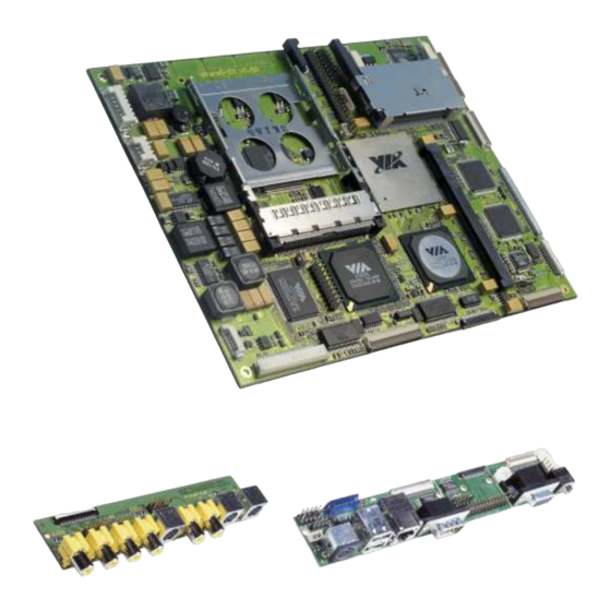
Technical Manual ePanel-C3 Version 1.04 10. EVALUATION I/O-ADAPTERS Kontron provides you with the evaluation I/O-adapters which makes all interfaces supported by ePanel-C3 easy accessible. Following interfaces are accessible on ePanel-ADAPT: Sound output (Stereo) Sound input (Stereo) Microphone input (Mono) Three USB-ports... - Page 68 Technical Manual ePanel-C3 Version 1.04 Following interfaces are accessible on ePanel-ADAPT-TV: Video inputs (2x Composite, 2x S-Video, 1x RGB) Video Outputs (1x Composite, 1x S-Video, 1x RGB) Mechanical dimension: 140,00 x 30,00 mm The schematics of the I/O-adapter ePanel-ADAPT-TV is available as PDF-file on the support page www.kontron-emea.com.
-
Page 69: Specifications
Technical Manual ePanel-C3 Version 1.04 11. SPECIFICATIONS 11.1. Mechanical specifications Dimensions (length x width): 180,0 x 140,0 mm Height: approx. 15 mm (21mm with Heatspreader and Fan) 11.2. Electrical specifications Supply voltage: 8V DC up to 28V DC +/- 10%... -
Page 70: Literature, Standards, Links
Version 1.04 12. LITERATURE, STANDARDS, LINKS It is not in the responsibility of Kontron to provide you with information on standard PC technology. Please find below a selection of different information sources for your convenience. 12.1. ISA-Bus, standard connectors •... -
Page 71: Document Revision History
Technical Manual ePanel-C3 Version 1.04 13. DOCUMENT REVISION HISTORY Filename Date Edited by Alteration to previous document revision ePanel-C3_M100.DOC 09/01/04 D.Piper, Initial Release L.Trotter ePanel-C3_M101.DOC 09/13/04 L.Trotter Preliminary Release ePanel-C3_M102.DOC 06/01/06 M. Hüttmann, Update BIOS Release 2.00 V. Irion ePanel-C3_M103.DOC 01/10/07 S.
Need help?
Do you have a question about the ePanel-C3 and is the answer not in the manual?
Questions and answers