Table of Contents
Advertisement
Advertisement
Table of Contents

Related Manuals for Kontron ETX-CD


Summary of Contents for Kontron ETX-CD
- Page 1 ETX®-CD Document Revision 130 www.kontron.com...
-
Page 3: Table Of Contents
3.11 Heatspreader..........................20 3.12 Onboard Fan Connector........................ 21 3.12.1 Electrical Characteristics......................23 Features and Interfaces...............24 LPC............................24 M.A.R.S............................ 25 JIDA16 and JIDA32........................26 K-Station 1..........................27 GPIO - General Purpose Input and Output..................28 Watchdog Timer.......................... 29 Speedstep Technology......................... 30 www.kontron.com... - Page 4 ETX®-CD / C-States............................ 31 ACPI Suspend Modes and Resume Events..................32 4.10 ISA Bus Limitation........................33 System Resources................34 Interrupt Request (IRQ) Lines......................34 Direct Memory Access (DMA) Channels.....................36 Memory Area..........................36 I/O Address Map......................... 36 Inter-IC (I2C) Bus........................36 System Management (SM) Bus.......................
-
Page 5: User Information
“as-is” and is subject to change without notice. For the circuits, descriptions and tables indicated, Kontron assumes no responsibility as far as patents or other rights of third parties are concerned. -
Page 6: Warranty
This Kontron Europe GmbH product is warranted against defects in material and workmanship for the warranty period from the date of shipment. During the warranty period, Kontron Europe GmbH will at its discretion decide to repair or replace defective products. -
Page 7: Introduction
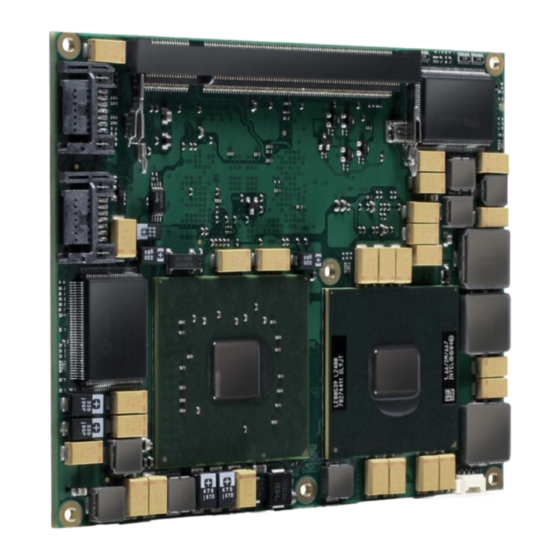
2 Introduction Product Description Based on the ETX® standard, Kontron’s ETX®-CD, powered by a variety of Intel Pentium core duo processors, is a next- generation embedded module that brings advanced technology to tomorrow’s applications, as well as continuing today’s legacy devices. Built around serial differential signaling technologies, ETX®-CD modules incorporate the following interfaces into a 95 x 114 small form factor embedded module: »... -
Page 8: Etx® Benefits
ETX®-CD / Introduction ETX® Benefits Embedded technology extended (ETX) modules are very compact (114 x 95 mm), highly integrated computers. All ETX® modules feature a standardized form factor and a standardized connector layout that carry a specified set of signals. This standardization allows designers to create a single-system baseboard that can accept present and future ETX®... -
Page 9: Specification
ETX®-CD, Heatspreader, through hole 18030-0000-99-0C01 ETX®-CD, Passive Cooling Solution, threaded 18030-0000-99-0CO2 ETX®-CD, Active Cooling Solution, threaded 96006-0000-00-4 ADA-ETX-CD-FC4 (SDVO FFC45 to 2xDVI Adaptor) 96006-0000-00-5 ADA-SDVOB-FC5 (SDVO FFC45 to 1xDVI Adaptor) 96006-0000-00-6 ADA-SDVOB-LVDS (SDVO FFC45 to LVDS Adaptor) 9-5000-0352 ADA-LVDS-DVI 18bit (LVDS to DVI converter) -
Page 10: Functional Specification
ETX®-CD / Specification Functional Specification Processor The Intel® Core™ Duo / Celeron® (Yonah / Merom) CPU supports: » Intel® Hyper-Threading Technology (HTT) » Enhanced Intel SpeedStep® Technology (EIST) » Thermal Monitoring Technologies » Idle States (C-States) » Execute Disable Bit Processor # of Cores Lithography... - Page 11 Ethernet The Intel 82562GZ ethernet supports: » Jumbo Frames » Time Sync Protocol Indicator » WOL (Wake On LAN) » PXE (Preboot eXecution Environment) Kontron Features I2C/SMB support: YES/YES M.A.R.S. support Embedded API JIDA16 / JIDA32 JIDA32 Applications / K-Station...
- Page 12 Misc Power Management DPST 2.0 Power Consumption and Performance Full Load Power Consumption 19 - 40W Kontron Performance Index 1387-3296 Kontron Performance/Watt 71 - 103 Detailed Power Consumption measurements in all states and bechmarks for CPU, Graphics and Memory performance are available in Application Note...
-
Page 13: Block Diagram
ETX®-CD / Specification Block Diagram... -
Page 14: Electrical Specification
ETX®-CD / Specification Electrical Specification 3.4.1 Supply Voltage Following supply voltage is specified at the ETX® connector: Supply Voltage: 5V +/- 5% 5V_Stb: 5V DC +/- 5% 3.4.2 Power Supply Rise Time » The input voltages shall rise from ≤10% of nominal to within the regulation ranges within 0.1ms to 20ms. »... -
Page 15: Environmental Specification
-40°C to +85°C Please see chapter Product Specification for available variants for extended or industrial temperate grade With Kontron heatspreader plate assembly The operating temperature defines two requirements: » the maximum ambient temperature with ambient being the air surrounding the module. -
Page 16: Standards And Certifications
UL Listings: » NWGQ2.E304278 » NWGQ8.E304278 WEEE Directive WEEE Directive 2002/96/EC is not applicable for Computer-on-Modules. Conformal Coating Conformal Coating is available for Kontron Computer-on-Modules and for validated SO-DIMM memory modules. Please contact your local sales or support for further details. - Page 17 The ETX® form factor Computer-on-Modules successfully passed shock and vibration tests according to » IEC/EN 60068-2-6 (Non operating Vibration, sinusoidal, 10Hz-4000Hz, +/-0.15mm, 2g) » IEC/EN 60068-2-27 (Non operating Shock Test, half-sinusoidal, 11ms, 15g) Validated in Kontron reference housing for EMC the ETX®-CD follows the requirements for electromagnetic compatibility standards » EN55022...
-
Page 18: Mtbf
Estimated RTC battery life (as opposed to battery failures) is not accounted for in the above figures and need to be considered for separately. Battery life depends on both temperature and operating conditions. When the Kontron unit has external power; the only battery drain is from leakage paths. -
Page 19: Mechanical Specification
ETX®-CD / Specification Mechanical Specification » 95.0 mm x 114.0 mm » Hight approx. 12mm (0.4”) CAD drawings are available at EMD CustomerSection Module Drillhole Dimension The not shown drill holes match with the ETX® specification. The maximum height of electrical components on the bottom side of the module is specified with 2.0mm in the ETX@ specification. -
Page 20: Thermal Management
Thermal Management A heatspreader plate assembly is available from Kontron Europe GmbH for the ETX®-CD. The heatspreader plate on top of this assembly is NOT a heat sink. It works as a ETX®-standard thermal interface to use with a heat sink or other cooling device. -
Page 21: Onboard Fan Connector
ETX®-CD / Specification 3.12 Onboard Fan Connector This section describes how to connect a fan to the connector located directly on the ETX®-CD. With certain BIOS-settings it is possible to control the fan depending on the Active Trip Point temperature. The fan switches on/off depending on the adjusted Active Trip Point temperature. - Page 22 ETX®-CD / Specification The onboard fan connector (J6) can be found near the northbridge at the corner of the module. Connector J1 has following specification: » Part number (Molex) J8: 53261-0390 » Mates with: 51021-0300 » Crimp terminals: 50079-8100 The Pin assignement is: »...
-
Page 23: 3.12.1 Electrical Characteristics
ETX®-CD / Specification 3.12.1 Electrical Characteristics Vcc = 5 V Imax (continuous) = 0,68 A Imax (pulsed) = 2 A Sense (Tacho-pulse) = 4 Pulses per turn The 5 V output is not short circuit proof. The user has to ensure that the circuit is protected externally, for example by a fuse on the backplane. -
Page 24: Features And Interfaces
LPC. This leads to limitations for ISA bus and SIO (standard I/O´s like Floppy or LPT interfaces) implementations. All Kontron COM Express® Computer-on-Modules imply BIOS support for following external baseboard LPC Super I/O controller features for the Winbond/Nuvoton 5V 83627HF/G and 3.3V 83627DHG-P:... -
Page 25: M.a.r.s
ETX®-CD / Features and Interfaces M.A.R.S. The Smart Battery implementation for Kontron Computer-on-Modules called Mobile Application for Rechargeable Systems is a BIOS extension for external Smart Battery Manager or Charger. It includes support for SMBus charger/selector (e.g. Linear Technology LTC1760 Dual Smart Battery System Manager) and provides ACPI compatibility to report battery information to the Operating System. -
Page 26: Jida16 And Jida32
ETX®-CD / Features and Interfaces JIDA16 and JIDA32 JIDA16 (JUMPtec® Intelligent Device Architecture) is a BIOS interface which allows programs running in Real Mode operating systems (i.e. MS DOS) to call certain functions implemented in the BIOS. These functions can be used to get module information, make settings and access the I2C Bus and the Watchdog unit. -
Page 27: K-Station 1
Based on the JIDA32 interface users can implement advanced board functionality in their application. As an example utility Kontron provides K-Station for most 32bit Windows Operating Systems. K-Station 1 is a summary of command line utilities (Shell Tools) for easy access to JIDA32 BIOS implementations. Second part of K-Station is a JAVA based example GUI which gives a view an all available features using the Shell Tools. -
Page 28: Gpio - General Purpose Input And Output
ETX®-CD / Features and Interfaces GPIO - General Purpose Input and Output The offers 4 General Purpose Input (GPI) pins and 4 General Purpose Output (GPO) pins. On a 3.3V level digital in- and outputs are available. Signal Description GPI0 General Purpose Input 0 GPI1 General Purpose Input 1... -
Page 29: Watchdog Timer
You can program the timeout period for the watchdog timer in two ranges: » 1-second increments from 1 to 255 seconds » 1-minute increments from 1 to 255 minutes Contact Kontron Embedded Modules technical support for information on programming and operating the WDT. -
Page 30: Speedstep Technology
ETX®-CD / Features and Interfaces Speedstep Technology The Intel® processors offers the Intel® Enhanced SpeedStep™ technology that automatically switches between maximum performance mode and battery-optimized mode, depending on the needs of the application being run. It let you customize high performance computing on your applications. When powered by a battery or running in idle mode, the processor drops to lower frequencies (by changing the CPU ratios) and voltage, conserving battery life while maintaining a high level of performance. -
Page 31: C-States
ETX®-CD / Features and Interfaces C-States New generation platforms include power saving features like SuperLFM, EIST (P-States) or C-States in O/S idle mode. Activated C-States are able to dramatically decrease power consumption in idle mode by reducing the Core Voltage or switching of parts of the CPU Core, the Core Clocks or the CPU Cache. -
Page 32: Acpi Suspend Modes And Resume Events
ETX®-CD / Features and Interfaces ACPI Suspend Modes and Resume Events The ETX®-CD supports the S3 state (=Save to Ram). S4 (=Save to Disk) is not supported by the BIOS (S4_BIOS) but S4_OS is supported by the following operating systems: »... -
Page 33: Isa Bus Limitation
ETX®-CD / Features and Interfaces 4.10 ISA Bus Limitation Memory accesses are not supported on the ISA bus. I/O accesses are only supported if they fall into one of the 4 generic decode ranges provided by the chipset. If a plugin ISA card is using registers in I/O space, this address range has to be →... -
Page 34: System Resources
ETX®-CD / System Resources 5 System Resources Interrupt Request (IRQ) Lines In 8259 PIC mode: IRQ # Used For Available Comment Timer0 Keyboard Slave 8259 COM2 Note (1) COM1 Note (1) LPT2 Note (2) Floppy Drive Controller Note (1) LPT1 Note (1) COM3 Note (2) - Page 35 ETX®-CD / System Resources In APIC mode: IRQ # Used For Available Available for PCI Comment Timer0 Keyboard Slave 8259 COM2 Note (1) COM1 Note (1) PCI/LPT2 Note (2) Floppy Drive Controller Note (1) LPT1 Note (1) System Control Interrupt (3) COM3 Note (2) COM4...
-
Page 36: Direct Memory Access (Dma) Channels
ETX®-CD / System Resources Direct Memory Access (DMA) Channels DMA # Used for Available Comment If the “used-for” device is disabled in setup, the corresponding DMA channel is available for other devices. Unavailable if LPT is used in ECP mode. Cascade Memory Area Upper Memory... -
Page 37: Etx® Connectors
ETX®-CD / ETX® Connectors 6 ETX® Connectors The pinouts for ETX® Interface Connectors X1, X2, X3, and X4 are documented for convenient reference. Please see the ETX® Specification and ETX® Design Guide for detailed, design-level information. Connector Locations General Signal Description Term Description IO-3,3... -
Page 38: Connector X1 (Pci Bus, Usb, Audio)
ETX®-CD / ETX® Connectors Connector X1 (PCI bus, USB, Audio) Signal Signal Signal Signal VCC * VCC * PCICLK3 PCICLK4 SERR# GPERR# RESERVED PCICLK1 PCICLK2 PME# USB2# REQ3# GNT3# LOCK# DEVSEL# GNT2# TRDY# USB3# REQ2# GNT1# IRDY# STOP# REQ1# FRAME# USB2 GNT0# RESERVED... -
Page 39: Connector X1 Signal Levels
ETX®-CD / ETX® Connectors 6.3.1 Connector X1 Signal Levels Signal Description Type Termination Comment Ground Ground PCICLK3 PCI Clock Slot 3 O-3,3 PCICLK4 PCI Clock Slot 4 O-3,3 Ground Ground PCICLK1 PCI Clock Slot 1 O-3,3 PCICLK2 PCI Clock Slot 2 O-3,3 REQ3# PCI Bus Request 3... - Page 40 ETX®-CD / ETX® Connectors FRAME# PCI Bus Cycle Frame IO-3,3 PU 8k2 3,3V USB2 USB Data+ , Port2 IO-3,3 int. PD 15k in ICH7 Ground Ground AD16 PCI Adress & Data Bus line IO-3,3 CBE2# PCI Bus Command and Byte enables 2 IO-3,3 AD17 PCI Adress &...
-
Page 41: Connector X1 Signal Description
16 of Connector X1 are used to connect to the +3.3V ±5% power supply. The maximum external load is 500mA. Contact Kontron Embedded Systems Technical Support for help with this feature. Do not connect 3.3 V pins to external 3.3 V supply. -
Page 42: Connector X2 (Isa Bus)
ETX®-CD / ETX® Connectors Connector X2 (ISA Bus) Signal Signal Signal Signal VCC * VCC 1) SD14 SD15 IRQ5 SD13 MASTER# IRQ6 SD12 DREQ7 IRQ7 SD11 DACK7# SYSCLK SD10 DREQ6 SA10 REFSH# DACK6# SA11 DREQ1 DREQ5 SA12 DACK1# MEMW# DACK5# MEMR# DREQ0 SA13... -
Page 43: Connector X2 Signal Levels
ETX®-CD / ETX® Connectors 6.4.1 Connector X2 Signal Levels Signal Description Type Termination Comment Ground Ground SD14 ISA Data Bus IO-5 PU 8k2 5V SD15 ISA Data Bus IO-5 PU 8k2 5V SD13 ISA Data Bus IO-5 PU 8k2 5V MASTER# ISA 16-Bit Master PU 330R 5V... - Page 44 ETX®-CD / ETX® Connectors SA12 ISA Adress Bus O-3,3 PU 8k2 5V DACK1# ISA DMA Acknowledge 1 IO-3,3 Ground Ground SA13 ISA Adress Bus O-3,3 PU 8k2 5V DREQ3 ISA DMA Request 3 I-3,3 PD 8k2 SA14 ISA Adress Bus O-3,3 PU 8k2 5V DACK3#...
-
Page 45: Connector X2 Signal Description
ETX®-CD / ETX® Connectors 6.4.2 Connector X2 Signal Description ISA Bus The implementation of this subsystem complies with the ETX® Specification. Implementation information is provided in the ETX® Design Guide. Refer to the documentation for additional information. Restrictions: Memory Transfer: According to the used LPC 2 ISA solution only memory transfer in the Firmware HUB memory range and with Firmware HUB commands is possible. - Page 46 ETX®-CD / ETX® Connectors - the enclosure of the peripheral device fulfils the fire-protection requirements of IEC/EN60950. 2) This signal is not supported on the ETX®-CD. Parallel Port / Floppy Interfaces You can configure ETX®-CD’s parallel port interfaces as conventional PC parallel ports or as an interface for a floppy-disk drive.
-
Page 47: Connector X3 (Signal Levels)
ETX®-CD / ETX® Connectors 6.5.1 Connector X3 (Signal Levels) Signal Description Type Termination Comment Ground Ground Analog Video Out RGB - Red Channel Analog Video Out RGB - Blue Channel Horizontal Synchronization Pulse O-3,3 Analog Video Out RGB - Green Channel Vertical Synchronization Pulse O-3,3 DDCK... - Page 48 ETX®-CD / ETX® Connectors Ground Ground RTS2# Request to Send COM2 PU 100k 5V PD5 / nc LPT Data Bus D5 IO-5 DTR2# Data Terminal Ready COM2 PU 100k 5V SLIN# / STEP# LPT Select / Floppy Motor Step DCD2# Data Carrier Detect COM2 PU 100k 5V PD4 / DSKCHG#...
-
Page 49: Connector X3 Signal Description
PC/AT settings. You can change some mouse-related parameters from the BIOS setup. IrDA The ETX®-CD is capable of IrDA SIR operation. This feature is implemented in the Winbond 83627HF. Contact Kontron Embedded Systems for help with this feature. - Page 50 ETX®-CD / ETX® Connectors The parallel-communication interface uses I/O, IRQ, and DMA resources. The resources are allocated by the BIOS during POST configuration and are set to be compatible with common PC/AT settings. You can change some parameters of the parallel-communication interface through the BIOS setup.
-
Page 51: Connector X4 Subsystems
ETX®-CD / ETX® Connectors Connector X4 Subsystems 6.6.1 Connector X4 (IDE 1, IDE 2, Ethernet, Miscellaneous) Signal Signal Signal Signal SIDE_IOW# 2) PIDE_IOR# 5V_SB PWGIN SIDE_DRQ 2) PIDE_IOW# PS_ON SPEAKER SIDE_D15 2) PIDE_DRQ PWRBTN# BATT SIDE_D0 2) PIDE_D15 KBINH# LILED# SIDE_D14 2) PIDE_D0 RSMRST#... -
Page 52: Connector X4 (Signal Levels)
ETX®-CD / ETX® Connectors 6.6.2 Connector X4 (Signal Levels) Signal Description Type Termination Comment Ground Ground 5V_SB Supply of internal suspend Circuit PWGIN Power Good / Reset Input I-3,3 PU 10k 3,3V_SB PS_ON Power Supply On O-3,3 PU 10k 3,3V SPEAKER Speaker Output O-3.3... - Page 53 ETX®-CD / ETX® Connectors Ground Ground SIDE_D2 PIDE_D13 Primary IDE Data Bus SIDE_D12 PIDE_D2 Primary IDE Data Bus SIDE_D3 PIDE_D12 Primary IDE Data Bus SIDE_D11 PIDE_D3 Primary IDE Data Bus SIDE_D4 PIDE_D11 Primary IDE Data Bus SIDE_D10 PIDE_D4 Primary IDE Data Bus SIDE_D5 PIDE_D10 Primary IDE Data Bus...
-
Page 54: Connector X4 Signal Description
ETX® Specification. Implementation information is provided in the ETX® Design Guide. Refer to the documentation for additional information. External SMI Interrupt Contact Kontron Embedded Modules GmbH technical support for information on this feature. Miscellaneous Circuits Speaker The implementation of the speaker output complies with the ETX® Specification. Implementation information is provided in the ETX®... - Page 55 The I2C Bus is implemented by using general purpose I/O. You also can access the I2C Bus via JUMPtec’s Intelligent Device Architecture (JIDA) BIOS functions. For additional information, refer to the ETX® Design Guide, I2C application notes and JIDA specifications which are available at the Kontron Web site. SM Bus System Management (SM) bus signals are connected to the SM bus controller, which is located in the southbridge (Intel 82801GBM) device.
-
Page 56: Feature Connector J11
ETX®-CD / ETX® Connectors Feature Connector J11 6.7.1 SDVO Output The ETX®-CD Serial Digital Video Out port is integrated in the Intel® 945GM northbridge. It has the following features: » Serial Digital Video Out Port (SDVOB & SDVOC) support » Two 12-bit channels »... - Page 57 ETX®-CD / ETX® Connectors SDVO_TVCLKINN TV Clock Input negative SDVO_TVCLKINP TV Clock Input positive GND13 Ground SDVO_CTRCLK I2C based control signal for SDVO devices; clock SDVO_CTRLDATA I2C based control signal for SDVO devices; data RESET# Reset signal 5V power 5V power 5V power Reserved Reserved...
-
Page 58: Bios Operation
Copyright 1985-2006 Phoenix Technologies Ltd. All Rights Reserved Kontron(R) BIOS Version <MCALRXXX> The PhoenixBIOS Setup Utility changes system behavior by modifying the BIOS configuration. The setup program uses a number of menus to make changes and turn features on or off. - Page 59 ETX®-CD / BIOS Operation The Main Menu then appears. The Setup Screen is composed of several sections: Setup Screen Location Function Menu Bar Lists and selects all top level menus. Legend Bar Right side Bottom Lists setup navigation keys. Item Specific Help Window Right side Top Help for selected item.
-
Page 60: Bios Setup Menu
ETX®-CD / BIOS Operation BIOS Setup Menu 7.2.1 Info Screen... -
Page 61: Main Menu
ETX®-CD / BIOS Operation 7.2.2 Main Menu Feature Option Description System Time [hh:mm:ss] <Tab>, <Shift-Tab>, or <Enter> selects field System Date [mm-dd-yyyy] <Tab>, <Shift-Tab>, or <Enter> selects field Legacy Diskette A Disabled Selects floppy type. Note that 1.25 MB references a 1024 byte sector Japanese media format. - Page 62 ETX®-CD / BIOS Operation IDE Channels Submenu Feature Option Description Type User Selects the type of the IDE Devices connected to the Auto system none ATAPI Removable CD-ROM IDE Removable Other ATAPI Multi-Sector Transfers Disabled Specify the number of sectors per block for multiple 2 Sectors sector transfers 4 Sectors...
-
Page 63: Advanced
ETX®-CD / BIOS Operation 7.2.3 Advanced... - Page 64 ETX®-CD / BIOS Operation CPU Control Feature Option Description Core Multi-Processing Enabled Enables and disables the 2nd CPU core Disabled Processor Power Management Enabled Selects the processor power management GV3 only C-states only Disabled Enabled Intel® Virtualization Technology When enabled a virtual machine can utilize the additional hardware virtualization capabilities.
- Page 65 ETX®-CD / BIOS Operation Advanced Chipset Control...
- Page 66 ETX®-CD / BIOS Operation Chipset Control Feature Option Description Memory Throttling Enabled Controls throttling and bandwidth limiting for the 945 Disabled Clock generator Default “Program” allows to enable/disable manual change of Spread Spectrum and FSB Program PCI Clock Run Enabled If Enabled the Clock Run logic will stop the PCI clocks Disabled Serial IRQ Quiet Mode...
- Page 67 ETX®-CD / BIOS Operation Integrated Video Feature Option Description IGD - Device 2 Auto Disabled IGD - Device 2, Function 1 Auto Disabled DVMT 3.0 Mode Fixed Selectes the mode of the DMBT graphic memory DVMT allocation Combo Pre-Allocated Memory Size 1 MB Sets the size of the pre-allocated graphics memory 8 MB...
- Page 68 ETX®-CD / BIOS Operation ISA Options Feature Option Description ISA Bridge Enabled Enables/disables the ISA bridge Disabled 8 Bit I/O recovery 3.5 SYSCLK Sets the 8 Bit I/O recovery time 4.5 SYSCLK … 10.5 SYSCLK 16 Bit I/O recovery 3.5 SYSCLK Sets the 16 Bit I/O recovery time 4.5 SYSCLK …...
- Page 69 ETX®-CD / BIOS Operation PCI/PNP Configuration Feature Option Description PNP OS installed Other Selects the most used OS Win95 Win98 WinMe Win2000 WinXP Reset Configuration Data “Yes” will clear the ESCD PCI IRQ line 1 to 8 Auto Select PCI devices can use hardware interrupts (IRQs). It can also be auto selected...
- Page 70 ETX®-CD / BIOS Operation PCI/PNP ISA IRQ Resource Exclusion Feature Option Description IRQ 3, 4, 5, 7, 9, 10, 11 Available Reserved...
- Page 71 ETX®-CD / BIOS Operation Cache Memory Feature Option Description Memory Cache Enabled Enables/disables the memory cache system Disabled Cache System / Video BIOS area Write Protect Cache setting for System BIOS area uncached Cache Base 0-512k Uncached Uncached = Disabled: This block is not cached at all Cache Base 512k-640k Write Through USWC Caching: Uncached Speculative Write Combined...
- Page 72 ETX®-CD / BIOS Operation I/O Device Configuration Feature Option Description Parallel ATA Enabled Enables/disables the PATA Disabled Primary IDE UDMA66/100 Enabled Enables/disables UDMA 66/100 modes Disabled Serial ATA Enabled Enables/disables SATA Disabled SATA Controller Mode Option Compatible Compatible: SATA/PATA devices are driven in legacy Enhanced mode Enhanced mode: SATA/PATA devices are driven in native...
- Page 73 ETX®-CD / BIOS Operation LAN Options Feature Option Description LAN Controller #1 Enabled Enables/disables the PATA Disabled Onboard LAN PXE ROM Enabled Enables/disables the LAN PXE boot ROM Disabled Enable WOL Enabled Enables/disables Wake on LAN Disabled...
- Page 74 ETX®-CD / BIOS Operation Super I/O Controller Options Feature Option Description Onboard LPT Auto Enables/disables the Parallel Port Enabled Disabled Serial Port A Enabled Enables/disables serial port A; Auto: will be initialized when detected Disabled Auto Base I/O address Base I/O address of COM port A Interrupt IRQ3 Selects interrupt of COM port A...
- Page 75 ETX®-CD / BIOS Operation USB ports Feature Option Description USB Controller Enabled Enables/disables the USB controller Disabled USB UHCI Ports 1, 2 and 3 Enabled Controls USB ports 1, 2 and 3 with two connectors each. Disabled USB EHCI Enabled Enables/disables USB 2.0 support Disabled Legacy USB Support...
- Page 76 ETX®-CD / BIOS Operation Console Redirection Feature Option Description Console Disabled Controls the serial console redirection. N/A UCR COM A UCR COM B UCR COM C UCR COM D JRC, Auto...
- Page 77 ETX®-CD / BIOS Operation Keyboard Features Feature Option Description NumLock Auto Selects Power-on state for NumLock Key Click Disabled Enables Key Click Enabled Keyboard auto-repeat rate 30/sec Selects key repeat rate 26.7/sec 21.8/sec 18.5/sec 13.3/sec 10/sec 6/sec 2/sec Keyboard auto-repeat delay ¼...
- Page 78 ETX®-CD / BIOS Operation Hardware Monitor Feature Option Description Hardware Monitor Enabled Controls the Hardware Monitor Disabled Edges/Revolution Select the number of ticks the fan generates in one revolution to display the fan speed correctly...
- Page 79 ETX®-CD / BIOS Operation Wachdog Settings Feature Option Description Mode Disabled Watchdog action Reset Timeout 1sec Max. trigger periode 5sec 10sec 30sec 1min 5.5min 10.5min 30.5min Delay 1sec Time until watchdog timer starts to count 5sec 10sec 30sec 1min 5.5min 10.5min 30.5min...
- Page 80 ETX®-CD / BIOS Operation Display Control Feature Option Description Display Mode CRT only CRT: Cathode Ray Tube LFP only LFP: LVDS flat panel (JILI) CRT + LFP EFP: Embedded flat panel (sDVO) LFP + EFP Flat Panel Type VGA 1×18 Select [Auto] for JILI or one of the predefined LCD’s SVGA 1×18 Use [Enter PAID] or [Enter FPID] to manually enter...
- Page 81 ETX®-CD / BIOS Operation Miscellaneous Settings Feature Option Description Summary Screen Disabled Display system configuration at boot Extended Dark Boot Disabled Prevent diagnostic screen output during boot Enabled Dark Boot Logo Use -/+ to select the Dark Boot logo 0 – Vendor Logo 1 –...
-
Page 82: Security
ETX®-CD / BIOS Operation 7.2.4 Security Feature Option Description Set Supervisor Password [a..z;0..9;+-#…] Allows to set Supervisor Password Clear All Passwords Clear Supervisor and Administrative Password Password on boot Disabled Enables/Disables password for boot process Enabled Fixed Disk boot sector Normal Enables/Disables Write protection of boot sector to protect against viruses... -
Page 83: Power
ETX®-CD / BIOS Operation 7.2.5 Power Feature Option Description Enable ACPI En/Disable ACPI BIOS (Advance Configuration and Power Interface) Enable ACPI _Sx state None This option allows to selectively enable Sx standby states for ACPI OS. Choosing ‘None’ will force the OS to have only S4 and S5 states. - Page 84 ETX®-CD / BIOS Operation CPU Thermal Control Feature Option Description Thermal Control Circuit Disabled Sets the mode of the Thermal Control Circuit TM1 and TM2 PROCHOT# Enable Enabled This function engages the Thermal Control Circuit when Disabled enabled DTS Enable Enabled Controls the DTS function of the processor Disabled...
- Page 85 ETX®-CD / BIOS Operation Passive Cooling The ACPI OS assesses the optimum CPU performance change necessary to lower the temperature using the following equation ?P[%] = TC1(Tn-Tn-1) + TC2(Tn-Tt) ?P is the performance delta, Tt is the target temperature = passive cooling trip point. The two coefficients TC1 and TC2 and the sampling period TSP are hardware dependent constants the end user must supply.
-
Page 86: Boot
ETX®-CD / BIOS Operation 7.2.6 Boot Feature Option Descpription Boot priority order 1:USB Key Keys used to view or configure devices: 2:USB CDROM Up and Down arrows select a device. ↔ 3:IDE CE <+> and moves the device up or down. 4:IDE 0 <f>... -
Page 87: Exit Menu
ETX®-CD / BIOS Operation 7.2.7 Exit Menu Feature Description Exit Saving Changes Exit System Setup and save your changes to CMOS. Exit Discarding Changes Exit utility without saving Setup data to CMOS. Load Optimized Defaults Load customer specific default values Load Setup Defaults Load default values for all SETUP items Discard Changes... - Page 88 188 Southern West 4th Ring Germany Beijing 100070, P.R.China Tel.: +49 (0)8165/ 77 777 Tel.: +1 888 294 4558 Tel.: + 86 10 63751188 Fax: +49 (0)8165/ 77 219 Fax: +1 858 677 0898 Fax: + 86 10 83682438 info@kontron.com info@us.kontron.com info@kontron.cn...
Need help?
Do you have a question about the ETX-CD and is the answer not in the manual?
Questions and answers