Table of Contents
Advertisement
Quick Links
Advertisement
Table of Contents
Troubleshooting

Related Manuals for Kontron ETXexpress-WPM


Summary of Contents for Kontron ETXexpress-WPM
- Page 1 ETXexpress-WPM User’s Guide Document Revision: 2.0 April 2009 Kontron America...
- Page 2 © 2006 Kontron, an International Corporation. All rights reserved. The information in this user’s guide is provided for reference only. Kontron does not assume any liability arising out of the application or use of the information or products described herein. This user’s guide may contain or reference information and products protected by copyrights or patents and does not convey any license under the patent rights of Kontron, nor the rights of others.
-
Page 3: Table Of Contents
Dimensions with Vertical Memory Sockets ..................28 Dimensions with RA Memory Socket ....................29 Environmental Specifications ....................30 5. CPU, Chipset, Super I/O and Memory ..............31 Intel Pentium M CPU.......................... 31 Intel Whitmore Lake Chipset ......................31 Winbond 83627HF Super I/O......................32 ETXexpress-WPM User’s Guide page... - Page 4 Introduction ..........................49 Determining the BIOS Version ......................49 Configuring the System BIOS....................50 Starting the Setup Utility ........................50 Main Menu ............................52 Advanced Menu..........................52 PCI/PNP Menu ...........................62 Boot Menu ............................64 Security Menu.............................64 Chipset Menu............................65 Exit Menu............................65 page 4 ETXexpress-WPM User’s Guide...
- Page 5 When booting, the system gives eight beeps ..................95 When booting the system, you hear two beeps ................. 95 The system runs very slowly ......................95 Troubleshooting Procedures ....................96 Common Problems........................97 Document Revision History ..................98 ETXexpress-WPM User’s Guide page...
- Page 6 Figure 7: Side View with BGA Processor and RA Memory ............30 Figure 8: 2nd Side View with BGA Processor and RA Memory ..........30 Figure 9: Connector Locations (top): ETXexpress-WPM with Vertical Memory Sockets ... 67 Figure 10: Connector Locations (top): ETXexpress-WPM with RA Memory Socket ....68 Figure 11: Connector Locations (bottom): ETXexpress-WPM............
-
Page 7: User Information
“as-is” and is subject to change without notice. For the circuits, descriptions and tables indicated, Kontron assumes no responsibility as far as patents or other rights of third parties are concerned. -
Page 8: Advisory Conventions
Disclaimer: We have tried to identify all situations that may pose a warning or caution condition in this user’s guide. However, Kontron does not claim to have covered all situations that might require the use of a Caution or Warning. -
Page 9: Guarantee And Warranty Policy
The limited warranty is void if the product has been subjected to alteration, neglect, misuse, or abuse; if any repairs have been attempted by anyone other than Kontron or its authorized agent; or if the failure is caused by accident, acts of God, or other causes beyond the control of Kontron or the manufacturer. -
Page 10: Return Procedure
Report for each unit, by serial number(s), as well as a copy of the original invoice showing the date of purchase. To reduce risk of damage, returns of product must be in a Kontron shipping container. If the original container has been lost or damaged, new shipping containers may be obtained from Kontron Customer Service at a nominal cost. -
Page 11: Technical Support
Before contacting Kontron technical support, please consult our Web site at http://www.kontron-em.com/index-en.html for the latest product documentation, utilities, and drivers. If the information does not help solve the problem, contact Kontron by telephone. Asia... - Page 12 This page intentionally left blank. page 12 ETXexpress-WPM User’s Guide...
-
Page 13: Getting Started
The power supplies produce high voltages and energy hazards, which can cause bodily harm. If you have any problems or questions about the unit, please contact Kontron Post-Sales Technical Support. WARNING High voltages are present inside a computer chassis when the unit’s power cord is plugged into an electrical outlet. -
Page 14: When Working Inside A Computer
Preventing Electrostatic Discharge Static electricity can harm system boards. Perform service at an ESD workstation and follow proper ESD procedure to reduce the risk of damage to components. Kontron strongly encourages you to follow proper ESD procedure, which can include wrist straps and smocks, when servicing equipment. - Page 15 Handle components and boards with care. Don’t touch the components or contacts on a board. Hold a board by its edges or by its metal mounting bracket. Do not handle or store system boards near strong electrostatic, electromagnetic, magnetic, or radioactive fields. ETXexpress-WPM User’s Guide page 15...
-
Page 16: Installation
3. Depending on your application, attach a fan and a heat sink to the ETXexpress Module if needed. 4. Insert the ETXexpress-WPM into Connector J22 on the Carrier Board and fasten module to carrier with appropriate hardware. 5. Plug the ATX power supply into a surge protector that is plugged into an electrical outlet. -
Page 17: Introduction
3. Introduction ETXexpress-WPM The ETXexpress-WPM (Type 3 COM Express Module) is based on the Intel® Pentium® M processor (up to 2 GHz) and the Intel Express chipset Intel 3100 (Whitmore Lake) that supports up to 12 PCI Express lanes for high I/O bandwidth. The ETXexpress- WPM (ETXexpress-WPM) is ideal for network equipment and telecom OEMs as well as test and measurement OEMs. -
Page 18: Etxexpress Module Overview
Web site: www.picmg.org. There is a fee for the document. Understanding ETXexpress Functionality The ETXexpress-WPM Type 3 Module contains two mounting connectors, each of which has two rows. The primary connector holds Row A and Row B. The secondary connector holds Row C and D. -
Page 19: Etxexpress Reference Documents
Initial bit rates for PCI Express reach 2.5Gb/s per lane direction, which equate to data transfer rates of approximately 200MB/s. A group of companies, headed by Kontron, developed the COM Express™ Specification so that high-speed interconnects such as USB 2.0 and Gigabit Ethernet would have an I/O architecture suitable for their high... -
Page 20: Thermal Management
The following heatsink assemblies are available: Part No. Description 38005-0000-95-1 Passive Heatsink for ETXexpress-WPM (BGA) 38005-0000-95-2 Active Heatsink for ETXexpress-WPM (BGA) These heatsinks are designed to used with a Ball Grid Array (BGA) package. addition, Pin Grid Array (PGA) versions are also available on request. The Active Heatsink includes a fan. -
Page 21: Photos
Photos Figure 1: ETXexpress-WPM with Vertical Memory Sockets ETXexpress-WPM User’s Guide page 21... -
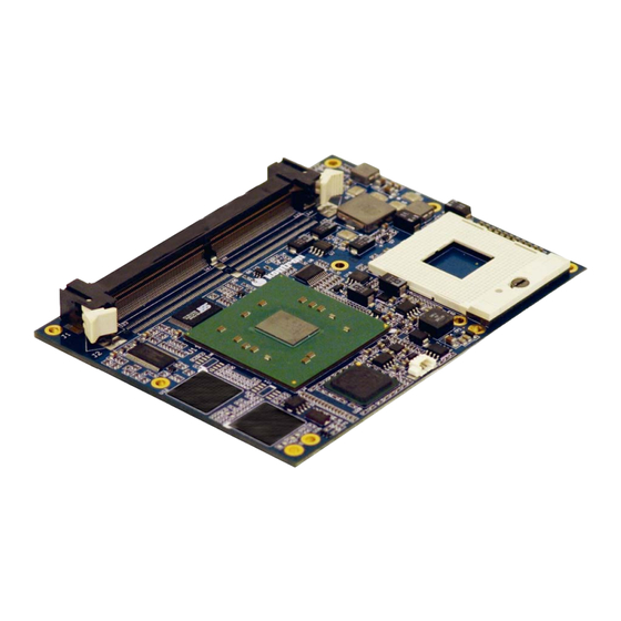
Page 22: Figure 2: Etxexpress-Wpm With Ra Memory Socket
Figure 2: ETXexpress-WPM with RA Memory Socket page 22 ETXexpress-WPM User’s Guide... -
Page 23: Block Diagram
Serial Port Enable (pulled low on BB) Core, Firmware Hub Switching Power Power 3.3V, Supplies In 12V 5V,12V E T X e -W P M B lo c k D ia g r a m ETXexpress-WPM User’s Guide page 23... - Page 24 (or PCIE [16-19]); the Intel 3100 chipset PCIE lanes for Port A (4-7) correspond to COM Express pins PEG [4-7] (or PCIE [20-23]); the Whitmore Lake PCIE lanes for Port B (0- 3) correspond to COM Express pins PCIE[0-3]. page 24 ETXexpress-WPM User’s Guide...
-
Page 25: Specifications
4. Specifications Functional Specifications The ETXexpress-WPM has the following features: Processor • Intel® Pentium® M 745 (400 MHz FSB, 1.8GHz, BGA or PGA package), OR • Pentium® M LV 738 (400 MHz FSB, 1.4GHz, BGA package), OR • Celeron M ULV 373 (400 MHz FSB, 1.0GHz, BGA), OR •... - Page 26 • NV-EEPROM for CMOS-setup retention without battery LCD and CRT Displays (Not supported) • None; use serial port from ETXexpress-WPM to a serial port on a different computer to transmit text data to a separate display. IDE (Not supported) •...
-
Page 27: Electrical Specifications
4x input • 4x output Electrical Specifications Supply Voltage • 12V DC +/- 5% Supply Voltage Ripple • Maximum 100 mV peak to peak 0 – 20 MHz Power Consumption • 60W @ 12V, 2GHz CPU ETXexpress-WPM User’s Guide page 27... -
Page 28: Mechanical Specifications
Mechanical Specifications Dimensions • 95.0 mm x 125.0 mm • Height approx. 18 mm Dimensions with Vertical Memory Sockets Figure 3: Dimensions with Vertical Memory Sockets page 28 ETXexpress-WPM User’s Guide... -
Page 29: Dimensions With Ra Memory Socket
Dimensions with RA Memory Socket Figure 4: Dimensions with RA Memory Socket Figure 5: Side View with Socketed Processor and RA Memory Figure 6: 2nd Side View with Socketed Processor and RA Memory ETXexpress-WPM User’s Guide page 29... -
Page 30: Environmental Specifications
Figure 8: 2nd Side View with BGA Processor and RA Memory Environmental Specifications Temperature • Operating: (with Kontron heat sink assembly 38005-0000-95-1 or 38005-0000- 95-2): Ambient temperature: 0° to +60° C Maximum heat sink temperature: 0° to +60° C (*) •... -
Page 31: Cpu, Chipset, Super I/O And Memory
The IMCH (Integrated Memory Control Hub) portion of the chipset supports the following: • Memory Interface • FSB (Front Side Bus) • PCI Express Interface (8 x lanes) • SMB (System Management Bus) ETXexpress-WPM User’s Guide page 31... -
Page 32: Winbond 83627Hf Super I/O
For complete information on BIOS setup options, see the BIOS Operation section in the back of this manual. Winbond 83627HF Super I/O The Winbond 83627HF Super I/O chip is installed on the ETXexpress Carrier Board, which carries the ETXexpress-WPM Module. The Winbond Super I/O chip supports the following functions: • Floppy drive •... -
Page 33: Memory
Memory The ETXexpress-WPM handles up to 4GB (future) of Double Data Rate memory (DDR2) up to 400MHz. DDR2 allows data to move on the rising and falling edges of clock cycles in a data burst. Configuration Memory does not require configuration. - Page 34 This page intentionally left blank. page 34 ETXexpress-WPM User’s Guide...
-
Page 35: Primary Connector (Rows A And B)
You can configure ACPI support from the BIOS Setup Utility. (Press the Delete button during reboot to see the BIOS Setup Utility.) Go to the Advanced Menu->ACPI Configuration Submenu. For complete information on BIOS setup options, see the BIOS Operation section in the back of this manual. ETXexpress-WPM User’s Guide page 35... -
Page 36: Ethernet
Submenu. You also can go to Advanced Menu -> Super I/O Configuration Submenu. For Parallel Port configuration, go to the Advanced Menu-> Super I/O Configuration Submenu. For complete information on BIOS setup options, see the BIOS Operation section in the back of this manual. page 36 ETXexpress-WPM User’s Guide... -
Page 37: Serial Ata
For complete information on BIOS setup options, see the BIOS Operation section in the back of this manual. USB 2.0 The ETXexpress-WPM provides support for up to 4x USB 2.0 ports for external peripherals. USB 2.0 is up to 40 times faster than the original USB standard. USB 2.0 is backward compatible with USB 1.1. - Page 38 This page intentionally left blank. page 38 ETXexpress-WPM User’s Guide...
-
Page 39: Secondary Connector (Rows C And D)
Firewire (1394b), USB 2.0, InfiniBand, and Gigabit Ethernet would have an I/O architecture suitable for high-speed transfers. The ETXexpress-WPM supports up to 12 PCI Express lanes across its two connectors. Their availability varies somewhat depending on whether the dual Gigabit Ethernet option (see below) is utilized. -
Page 40: Pci Bus
Type 3 ETXexpress COMs support an additional 2 GbE Ports. These ports have been implemented in the ETXexpress-WPM using the Intel 82573L GbE controller chip. Each 82573L controller chip uses one PCI Express lane. Optionally, if the GbE ports are not needed, then the board can be configured to free up the two PCI Express lanes that support the controllers and re-route them to the baseboard. -
Page 41: Super I/O Subsystems
Please note that the Winbond W83627HF is an optional baseboard feature; the BIOS installed on the ETXexpress-WPM supports it, but if it is not present, or if another SIO is used, then you must install a different BIOS, as appropriate, using a Flash utility. -
Page 42: Irda
Delete button during reboot to see the BIOS Setup Utility.) Go to the Advanced Menu->Super I/O Configuration Submenu. For complete information on BIOS setup options, see the BIOS Operation section in the back of this manual. page 42 ETXexpress-WPM User’s Guide... -
Page 43: Ps/2 Mouse
Delete button during reboot to see the BIOS Setup Utility.) Go to the Advanced Menu->Super I/O Configuration Submenu. For complete information on BIOS setup options, see the BIOS Operation section in the back of this manual. ETXexpress-WPM User’s Guide page 43... -
Page 44: Serial Ports (1 And 2)
Serial Ports (1 and 2) The ETXexpress-WPM Module provides support for up to one RS232 and one TTL serial interface. You can use COM2 for IrDA and ASK IR operation. Configuration The serial-communication interface uses I/O and IRQ resources. The resources are allocated by the BIOS during POST configuration and are compatible with common PC/AT settings. -
Page 45: 9: System Resources
Unavailable in Advanced Configuration and Power Interface (ACPI) mode. Used as System Control Interrupt (SCI) in ACPI mode. IRQs are available if IDE controller is either disabled in setup or if in Native IDE mode. ETXexpress-WPM User’s Guide page 45... -
Page 46: Direct Memory Access (Dma) Channels
Used for Available Comment Unavailable if AC97 Sound controller enabled If the “used-for” device is disabled in setup, the corresponding DMA channel is available for other devices. Unavailable if LPT is used in ECP mode. Cascade page 46 ETXexpress-WPM User’s Guide... -
Page 47: Memory Area
D0000h – DFFFFh ISA bus or shadow RAM E0000h – FFFFFh System BIOS No I/O Address Map The I/O-port addresses of the ETXexpress-WPM are identical to a standard PC/AT. The following I/O ports are used: I/O Address Used for Available... -
Page 48: System Management (Sm) Bus
Not to be used with any SM bus device except a battery. Clock generator Do not use under any circumstances. The standard ETXexpress-WPM power management BIOS does not support batteries. If you require further information, please contact Kontron Technical Support. page 48... -
Page 49: 10: Bios
10: BIOS Introduction The ETXexpress-WPM uses an AMIBIOS, which is located in the Flash memory. The BIOS version displays onscreen during the POST at boot. The device has an 8-bit access. The shadow RAM feature offers faster access (16 bit). You can update the BIOS using a Flash utility. -
Page 50: Configuring The System Bios
The AMIBIOS setup utility allows you to change system behavior by modifying the BIOS configuration. Setup-utility menus allow you to make changes and turn features on or off. AMIBIOS setup menus represent those found in most models of the ETXexpress-WPM. The BIOS setup utility for specific models can differ slightly. - Page 51 Go to Top of Screen F2/F3 Change Colors Load Failsafe Defaults Save and Exit Arrow key Select Item Enter Go to subscreen PGUP Previous page Go to Bottom of Screen Discard changes Load Optimal Defaults Exit ETXexpress-WPM User’s Guide page 51...
-
Page 52: Main Menu
Maximum: CPU speed is set to maximum. Minimum Speed Minimum: CPU speed is set to minimum. Automatic Automatic: CPU speed controlled by OS. Disabled Disabled: Default CPU speed. Note: In the Option column, bold shows default settings. page 52 ETXexpress-WPM User’s Guide... - Page 53 This will be effective only if device is accessed through the BIOS. IDE Detect Time Out (Sec) 0, 5, 10, 15, 20, 25, Select time out value for detecting 30, 35 ATA/ATAPI device(s). Note: In the Option column, bold shows default settings. ETXexpress-WPM User’s Guide page 53...
- Page 54 Parallel Port Mode Normal Allows BIOSto select Parallel Port mode. Bi-directional ECP & EPP Parallel Port IRQ IRQ5 Allows BIOS to select Parallel Port IRQ. IRQ7 Note: In the Option column, bold shows default settings. page 54 ETXexpress-WPM User’s Guide...
- Page 55 SATA devices. Feature Option Description 8AHCI Port0 , Port 1, Port2, Auto Select the type of device connected to the Not Installed system. Port3 Note: In the Option column, bold shows default settings. ETXexpress-WPM User’s Guide page 55...
- Page 56 Resume on PME# Disabled Disable/Enable PME to generate a wake event. Enabled Resume on RTC Alarm Disabled Disable/Enable RTC to generate a wake event. Enabled Note: In the Option column, bold shows default settings. page 56 ETXexpress-WPM User’s Guide...
- Page 57 Logging. Memory Buffer Event Disabled Enable or Disable Memory Buffer Error Logging Enabled Event Logging. PCI Error Logging Disabled Enable or Disable PCI Error Logging. Enabled Note: In the Option column, bold shows default settings. ETXexpress-WPM User’s Guide page 57...
- Page 58 Low Level. Passive Trip Point [75] Temperature of the CPU above which an ACPI OS will adjust cooling measure to High Level. Critical Trip Point [100] Temperature above which an ACPI OS will perform a shutdown. page 58 ETXexpress-WPM User’s Guide...
- Page 59 SB PCIe Port 0 Auto Disabled SB PCIe Port 1 Auto Disabled SB PCIe Port 2 Auto Disabled SB PCIe Port 3 Auto Disabled Note: In the Option column, bold shows default settings. ETXexpress-WPM User’s Guide page 59...
- Page 60 Support for ANSI/VT100 terminals. Sredir Memory Display No delay Gives the delay in seconds to display Delay Delay 1 Sec. memory information. Delay 2 Sec. Delay 4 Sec. Note: In the Option column, bold shows default settings. page 60 ETXexpress-WPM User’s Guide...
- Page 61 Ethernet Configuration Submenu Feature Options Description 10/100 Ethernet Enabled Enable/Disable the 10/100 Disable Ethernet Controller Gigabit Ethernet 1 Enabled Enable/Disable the Gigabit Disable Ethernet Controller Gigabit Ethernet 2 Enabled Enable/Disable the Gigabit Disable Ethernet Controller ETXexpress-WPM User’s Guide page 61...
-
Page 62: Pci/Pnp Menu
Reserved: Specified IRQ is reserved for use by legacy ISA devices. IRQ9 Available Available: Specified IRQ is available Reserved for use by PCI/PnP devices. Reserved: Specified IRQ is reserved for use by legacy ISA devices. page 62 ETXexpress-WPM User’s Guide... - Page 63 PCI/PnP devices. Reserved: Specified IRQ is reserved for legacy ISA devices. Reserved Memory Size Disabled Sets size of memory block to reserve for legacy ISA devices. Note: In the Option column, bold shows default settings. ETXexpress-WPM User’s Guide page 63...
-
Page 64: Boot Menu
Install or change password. Password Change User Enter New Password Install or change password. Password Boot Sector Virus Disabled Enable / Disable Boot Sector Protection Enable Virus Protection Note: In the Option column, bold shows default settings. page 64 ETXexpress-WPM User’s Guide... -
Page 65: Chipset Menu
F9 key can be used for this operation. Load Failsafe Defaults Load Failsafe Default values for all setup Cancel questions. F8 key can be used for this operation. Note: In the Option column, bold indicates default setting. ETXexpress-WPM User’s Guide page 65... -
Page 66: 11: Connectors And Pinouts
11: Connectors and Pinouts Virtually all I/O connectors for the ETXexpress-WPM are located on the ETXexpress Carrier Board (Brownsville.) For locations of connectors on the Carrier Board, please see the “Brownsville Carrier Board for ETXexpress Modules” Quick Start Guide, which is available from the Kontron Web site. -
Page 67: Figure 9: Connector Locations (Top): Etxexpress-Wpm With Vertical Memory Sockets
Figure 9: Connector Locations (top): ETXexpress-WPM with Vertical Memory Sockets Connector Description J1, J2 DDR2-DIMM Socket (400pin mini-DIMM) CPU Socket Fan Connector ETXexpress-WPM User’s Guide page 67... -
Page 68: Figure 10: Connector Locations (Top): Etxexpress-Wpm With Ra Memory Socket
Figure 10: Connector Locations (top): ETXexpress-WPM with RA Memory Socket Connector Description DDR2-DIMM Socket (400pin mini-DIMM) CPU Socket Fan Connector page 68 ETXexpress-WPM User’s Guide... -
Page 69: Connector Locations (Bottom)
Connector Locations (Bottom) The illustration below shows the location of the major components on the bottom side of the ETXexpress-WPM Module. Figure 11: Connector Locations (bottom): ETXexpress-WPM Connector Description Combined header: PLD programming and COM1 signals for debug ETXexpress Connector ITP700 Flex Debug Port ETXexpress-WPM User’s Guide... -
Page 70: Pin-Outs
(There is a fee for the specification.) Fan Connector (J4) Pin Function Tach Combined Header: PLD programming & COM1 Signals for debug (J5) Pin Function V_3V3SBY RSVD RSVD RSVD RSVD RS232_RTS1 RS232_TXD1# RS232_RXD1# RS232_CTS1 page 70 ETXexpress-WPM User’s Guide... -
Page 71: Etxexpress Connector (J6)
A45 USB0- USB1- C45 PCI_AD25 D45 PCI_AD30 A46 USB0+ USB1+ C46 PCI_AD27 D46 PCI_IRQC# A47 VCC_RTC EXCD1_PERST# C47 PCI_AD29 D47 PCI_IRQD# A48 EXCD0_PERST# EXCD1_CPPE# C48 PCI_AD31 D48 PCI_CLKRUN# A49 EXCD0_CPPE# SYS_RESET# C49 PCI_IRQA# D49 -nu- ETXexpress-WPM User’s Guide page 71... - Page 72 D96 GND A97 VCC_12V -nu- C97 BB_BIOS_WP# D97 -nu- A98 VCC_12V -nu- C98 -nu- D98 -nu- A99 VCC_12V -nu- C99 -nu- D99 -nu- A100 GND (FIXED) B100 GND (FIXED) C100 GND (FIXED) D100 GND (FIXED) page 72 ETXexpress-WPM User’s Guide...
- Page 73 Note: To protect external power lines of peripheral devices, make sure that: a) the wires have the right diameter to withstand the maximum available current b) the enclosure of the peripheral device fulfills the fire-protection requirements of IEC/EN60950. ETXexpress-WPM User’s Guide page 73...
- Page 74 This page intentionally left blank. page 74 ETXexpress-WPM User’s Guide...
-
Page 75: 12. Signal Descriptions
12. Signal Descriptions The ETXexpress-WPM signal descriptions are given in the following tables. Gigabit Ethernet Pin Type Pwr Rail / Description Tolerance GBE0_MDI[0:3]+ 3.3V max Gigabit Ethernet Controller 0: Media Dependent Interface Differential GBE0_MDI[0:3]- Analog Suspend Pairs 0,1,2,3. The MDI can operate in 1000, 100 and 10 Mbit / sec modes. - Page 76 PHY and may be as low as 0V and as high as 3.3V. The reference voltage output shall be current limited on the module. In the case in which the reference is shorted to ground, the current shall be 250 mA or less. page 76 ETXexpress-WPM User’s Guide...
- Page 77 Pin Type Pwr Rail / Description Support Tolerance EXCD[0:1]_CPPE# I 3.3V / 3.3V PCI ExpressCard: PCI Express capable card request, active CMOS low, one per card EXCD[0:1]_RST# 3.3V / 3.3V PCI ExpressCard: reset, active low, one per card CMOS ETXexpress-WPM User’s Guide page 77...
- Page 78 If the module is capable of supporting 66 MHz PCI operation, and if this input is held low by the Carrier Board, the module PCI interface shall operate at 33 MHz. page 78 ETXexpress-WPM User’s Guide...
- Page 79 3.3V Input to module from (optional) external keyboard controller that CMOS can be used to control the CPU A20 gate line. The A20GATE restricts the memory access to the bottom megabyte and is a legacy artifact of the PC-AT. Pulled low on the module. ETXexpress-WPM User’s Guide page 79...
- Page 80 Description Tolerance GPO[0:3] 3.3V / 3.3V General purpose output pins. Upon a hardware reset, these outputs CMOS should be low. GPI[0:3] 3.3V / 3.3V General purpose input pins. Pulled high internally on the module. CMOS page 80 ETXexpress-WPM User’s Guide...
- Page 81 Real-time clock circuit-power input. Nominally +3.0V. See Electrical Specifications section for details. Power Ground - DC power and signal and AC signal return path. All available GND connector pins shall be used and tied to Carrier Board GND plane. ETXexpress-WPM User’s Guide page 81...
-
Page 82: Signals Requiring Carrier Board Termination
GND with open drain drivers to indicate that the monitor’s current limit has been exceeded. Do not pull up these lines to 3.3V on the Carrier Board – this shall be done on the module. page 82 ETXexpress-WPM User’s Guide... -
Page 83: 13: Documents And Standards
IEEE 802.3-2002, IEEE Standard for Information technology, Telecom- munications and information exchange between systems—Local and metropolitan area networks—Specific requirements – Part 3: Carrier Sense Multiple Access with Collision Detection (CSMA/CD) Access Method and Physical Layer Specifications.” http://www.ieee.org ETXexpress-WPM User’s Guide page 83... - Page 84 JIDA, Technical Specification Nr. X00391.DOC, Revision 2.7, file name jida.pdf, available from your Kontron FAE. JIDA32, Kontron JIDA32 Library API Technical Manual, Revision 1.5, file name jida32.pdf, available from your Kontron FAE. JIDA32 BIOS Specification, Technical Specification Nr. X01363.DOC, file name X01363_Jida_BIOS_Spec.pdf, available from your Kontron FAE.
- Page 85 VESA Enhanced EDID Standard, Video Electronics Standards Organization, www.vesa.org VESA Enhanced Extended Display Identification Guide, Version 1.0, June 4, 2001, Copyright © 2001 Video Electronics Standards Organization, www.vesa.orgANSI/TIA/EIA-644-A-2001: Electrical Characteristics of Low Voltage Differential Signaling (LVDS) Interface Circuits, January 2001. 2Hhttp://www.ansi.org/ ETXexpress-WPM User’s Guide page 85...
- Page 86 This page intentionally left blank. page 86 ETXexpress-WPM User’s Guide...
-
Page 87: A: Terms And Definitions
Digital Video Interface – Digital format input to digital display EDID Extended Display Identification Data – This is a VESA standard for identifying display parameters to the host system by using a dedicated I2C bus. Electromagnetic Interference ETXexpress-WPM User’s Guide page 87... - Page 88 Term Definition ETXexpress™ The original Kontron name for the small form factor module standard that also is known as COM Express™. ETXexpress and COM Express™ are used interchangeably in this document. Express Card Small form factor hot-pluggable card for mobile computing. Express Card is the CardBus successor and uses USB or PCI Express x1 as the I/O interface.
- Page 89 2.5V, and 1.5V. Programmable Logic Device PICMG PCI Industrial Computer Manufacturing Group – a non-profit industry trade group that issues and maintains technical standards of interest to manufacturers of embedded and industrial computer boards and systems. ETXexpress-WPM User’s Guide page 89...
- Page 90 The Super I/O system interface is typically thru the LPC (Low Pin Count) bus. PCI-based Super I/Os also are available. Thin Film Transistor – a reference to a type of flat-panel display with an active transistor at each pixel. page 90 ETXexpress-WPM User’s Guide...
- Page 91 Universal Serial Bus – a general purpose, hot-pluggable serial I/O interconnect standard. Video Graphics Array VESA Video Electronics Standards Association – an industry trade group that issues standards relating to CRT and flat-panel displays. ETXexpress-WPM User’s Guide page 91...
- Page 92 This page intentionally left blank. page 92 ETXexpress-WPM User’s Guide...
-
Page 93: B: Troubleshooting
Avoid shorting the circuits as this can damage the computer. CAUTION The following procedures involve working with a device that is sensitive to static electricity. Use proper precautions to protect against electrostatic discharge (ESD). Only qualified personnel should attempt these procedures. ETXexpress-WPM User’s Guide page 93... -
Page 94: Unit Doesn't Power Up When Switched On
HDD parameters.) Non Plug-and-Play ISA card is not functioning properly If this card uses an IRQ, make sure that the particular IRQ is reserved to the 'ISA' bus in PCI/PnP setup in CMOS. page 94 ETXexpress-WPM User’s Guide... -
Page 95: When Booting, The Cpu Reports No Rom Basic
The system runs very slowly The system will run significantly slower if the cache memory has been disabled in the Advanced Setup in CMOS. (Cache memory is automatically disabled when you choose the Fail-Safe option in CMOS setup.) ETXexpress-WPM User’s Guide page 95... -
Page 96: Troubleshooting Procedures
Occasionally, Flash BIOS can be corrupted by hardware or software. Check the Kontron Web site for the latest version of BIOS and follow the steps for reflashing. When upgrading or adding hardware to an existing system, note board positions and cables. -
Page 97: Common Problems
When the short is removed, the power supply should automatically sense the removal of the short and restore operation. If cables become damaged, contact Kontron for repair or replacement System is not Memory is not seated... -
Page 98: Document Revision History
Edited by Changes Preliminary 0.1 29.05.06 JDL Released preliminary manual. Preliminary 0.2 20.10.06 RAH Updated preliminary manual. Preliminary 0.3 30.10.06 RAH Further updates based on given feedback. 23.02.09 CAV Various Updates 13.04.09 CAV BIOS Section Update page 98 ETXexpress-WPM User’s Guide...
Need help?
Do you have a question about the ETXexpress-WPM and is the answer not in the manual?
Questions and answers