
Related Manuals for Kontron ePanel-C3


Summary of Contents for Kontron ePanel-C3
- Page 1 Kontron Hamburg GmbH & Co.KG Marschnerstieg 7 22081 Hamburg / Germany Fon : +49 (0) 40 20 00 90-0 Fax : +49 (0) 40 20 00 90-10 www.kontron-hh.com Technical Manual ePanel-C3...
-
Page 2: Table Of Contents
Trademarks............................3 1.3. General ..............................3 1.4. Warranty ..............................3 1.5. Support, problems and failure analysis ....................4 INTRODUCTION .............................5 2.1. Kontron ePanel-Concept ........................5 2.2. ePanel-C3..............................6 FEATURES..............................7 RESOURCE LIST AND I/O MAP ........................9 CONNECTOR LOCATIONS AND PINOUTS ....................10 5.1. Connectors ............................10 5.2. Connector pinouts ..........................12 5.3. -
Page 3: User Information
Kontron will not be responsible for any defects or damages to other products not supplied by Kontron that are caused by a faulty Kontron product. -
Page 4: Support, Problems And Failure Analysis
1.5. Support, problems and failure analysis It is not in the responsibility of Kontron to supply you with informations about standard PC technology. Please find a selection of different information sources for your convenience in chapter Literature, standards, links Before contacting Kontron please check first our web page for available information (newest manuals, application notes etc.). -
Page 5: Introduction
Smallest Dimensions to meet smallest space requirements. With 252 cm the ePanel-C3 uses only a little more space compared to a current slot CPU, which needs 219 . But the most surprising fact is the module height. The ePanel-C3 measures only 21mm! How about the ISA bus? The only way to extend the capabilities of the board is to plug in PC-Cards or Mini-PCI-boards. -
Page 6: Epanel-C3
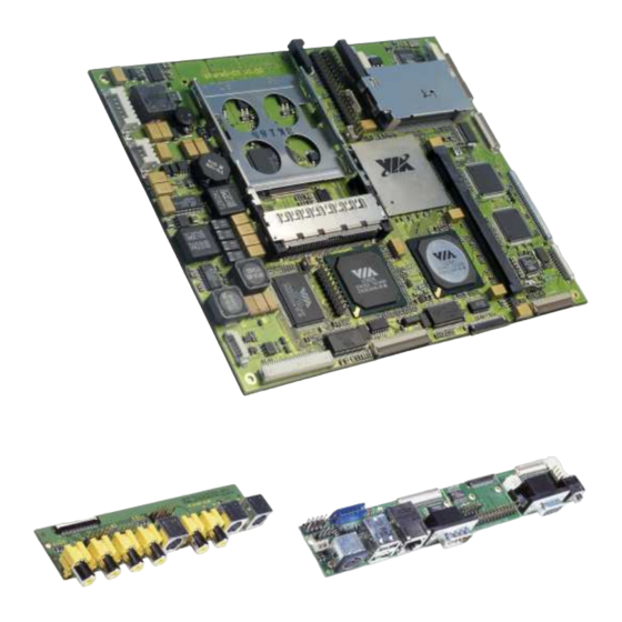
2.2. ePanel-C3 The ePanel-C3 is an extreme compact VIA Eden based PC module with consistent low power design. It is now possible to create modular systems, combining exchangeable CPU performance with systems, carrying only the connectors and additional functions needed. This reduces development costs and speeds up application design. -
Page 7: Features
3. FEATURES • 32-bit x86 processor Available with VIA EDEN ESP3000 (300 MHz), ESP7000 (733 MHz) or ESP10000 (1 GHz) for low power Applications, internal L1 Cache 128KB and 64KB L2 Cache • Chipset VIA CLE266 North Bridge and VIA VT8235 South Bridge •... - Page 8 • NV-Storage for CMOS-SETUP • Onboard Ethernet 10BASE-T/100BASE-TX LAN - VIA VT6103 10/100Mbit Base-T • Onboard VGA/LCD controller - VIA CLE266 with integrated VIA AGP Castle Rock Engine with MPEG-2 Decoder and 16, 32 or 64 MB shared memory Output: Single VGA/CRT 1 x TTL (FLEX32;...
-
Page 9: Resource List And I/O Map
D0000h – DFFFFh Plug&Play E0000h – EFFFFh System-BIOS F0000h – EC000h System BIOS ePanel-C3 The I/O-port addresses of the are functionally identical with a standard PC/AT. Following the additional I/O ports which are used on this board: I/O addr. used for... -
Page 10: Connector Locations And Pinouts
5. CONNECTOR LOCATIONS AND PINOUTS 5.1. Connectors Touch Panel Secondary IDE Digital Video Input TV In/Out Smart Battery DC Input FLEX32 JILI30 Debug Backlight Floppy Standard Port Secondary Port VGA/Sound Find more detailed information about the connectors in chapter “5.2 Connector Pinouts” Page 10 of 62 Pages... - Page 11 Mini -PCI Find more detailed information about the connectors in chapter “5.2 Connector Pinouts” Page 11 of 62 Pages...
-
Page 12: Connector Pinouts
5.2. Connector pinouts Pin-No. Smart Battery DC Input Backlight Floppy Matrix Touch Panel Debug Pin-No. Connector Connector Connector Connector Keyboard Connector Connector Connector 4/5/8Wire X2501 X2500 X1402 FDD1200 X2003 X2001 X2007 BAT+ +DCIN VCC5 BAT+ +DCIN BKLT_ADJ INDEX# VCC3 +5VDUAL BATT_SCL VCC5 KB_DO0... -
Page 13: Connector Pinouts
5.3. Connector pinouts Pin-No. Secondary IDE TV-Out/In Flatpanel Flatpanel (JILI) VGA/Sound COM2/LPT1 USB/COM1/ Pin-No. Connector Connector (FLEX32) Connector Connector Connector KEYB/PS2/ Connector Ethernet Connector X1100 X2000 X1401 X1403 X2004 X2006 X2002 IDE_RST# VCC5 VCC5 CVBS_IN1 PCLK FTX0- AUX_L KBCLK IDE_D7 FTX0+ DSR2# KBDAT... -
Page 14: Connector Pinouts
5.4. Connector pinouts Pin-No. IDE Connector TV-Out/In Flatpanel (JILI) VGA/Sound USB/COM1/ Pin-No. Connector Connector Connector KEYB/PS2/ Ethernet Connector X1100 X2000 X1403 X1402 X2002 SVY/RGB_G VCC12 VCC12 BCKBAT+ TXD+ VCC5 CVBS TXD- VCC5 VCC3 LILED VCC3 SPEEDLED VCC5 ACTLED VCC3 PWR_LED# MRESET# PWRBTN# Page 14 of 62 Pages... -
Page 15: Connector Pinouts
5.5. Connector pinouts Pin-No. Digital Video Flatpanel Fan Connector Backlight Pin-No. Input (JILI30) Compensation Connector Input X2005 X1400 X1200 X1404 +3,3V FTX0- UFAN VTIN YUV0 FTX0+ FANIN YUV1 FTX1- YUV2 FTX1+ YUV3 FTX2- YUV4 FTX2+ YUV5 YUV6 FTXC- YUV7 FTXC+ FTX3- FTX3+ STX0-... -
Page 16: Pin Descriptions
5.6. Pin descriptions 5.6.1. Connector X2004 ( VGA / Sound ) BCKBAT+ 3V backup cell input. BATT should be connected to a 3V backup cell for RTC operation and storage register non-volatility in the absence of system power. (typ. VBATT = 3V to 3.3V) VGA_HS Horizontal Sync: This output supplies the horizontal synchronization pulse to the monitor. - Page 17 5.6.2. Connector X1403 (JILI-Flatpanel-Interface) JILI_SCL, JILI_SDA These two pins are functionally suitable for a JILI interface between the graphics controller chip and the flatpanel cable. Open collector bidirectional signals ( LVTTL). FPVDD Controls panel digital power. LVTTL output. BKLT_ON Backlight power control signal. LVTTL output. FTX0..3 Differential LCD data output Signals for LVDS support (First port LVDS output).
- Page 18 5.6.4. Connector X2002 ( USB / COM1 / KEYB / PS2 / Ethernet ) DTR1# Active low data terminal ready output for the serial port. Handshake output signal notifies modem that the UART is ready to establish data communication link (TTL). RI1# Active low input for the serial port.
- Page 19 LILED The Link Integrity LED pin indicates link integrity. If the link is valid in either 10 or 100 Mbps, the LED is on; if link is invalid, the LED is off. SPEEDLED The Speed LED pin indicates the speed. The speed LED will be on at 100 Mbps and off at 10 Mbps. USB0+, USB0- Universal Serial Bus Port 0.
- Page 20 5.6.5. Connector X2006 ( COM2 / LPT1 ) All signals are TTL compatible. Active low pulse is used to strobe the printer data into the printer. AFD# Active low output causes the printer to automatically feed one line after each line is printed. PD0..PD7 Bi-directional parallel data bus is used to transfer information between CPU and peripherals.
- Page 21 5.6.6. Connector FDD1200 ( Floppy ) All signals are TTL compatible. DR0# Drive select 0. INDEX# Active low Schmitt Trigger input signal senses from the disk drive that the head is positioned over the beginning of a track, as marked by an index hole. TRK0# Active low Schmitt Trigger input signal senses from the disk drive that the head is positioned over the outermost track.
- Page 22 5.6.7. Connector X1100 ( Secondary IDE ) All signals are LVTTL compatible. IDE_D0..15 IDE ATA Data Bus. These are the Data pins connected to Secondary Channel. IDE_A0..2 IDE ATA Address Bus. These are the Address pins connected to Secondary Channel. IDE_CS0# IDE Chip Select 1 for Secondary Channel 0.
- Page 23 5.6.8. Connector X2501 ( Smart Battery System ) BAT+ Connect to positive terminal of battery. Connect to negative terminal of battery. BATT_SDA Smart battery data bus signal. Open collector bidirectional (TTL). BATT_SCL Smart battery clock signal. Open collector bidirectional (TTL). Thermal monitor input signal.
- Page 24 5.6.13. Connector X2003 ( Matrix Keyboard ) KB_DO 0..O7 Matrix keyboard outputs. Max. output voltage is 3.3V DC. KB_DI 0..I7 Matrix keyboard inputs. Max. input voltage is 3.3V DC. 5.6.14. Connector X2001 ( Touch Panel ) Touchpanel bottom driving signal. SW (Southwest) ) input for 5-wire touchpanels Touchpanel bottom sensing signal.
- Page 25 5.6.15. Connector X2007 ( Aux Interface ) DDC_SCL, DDC_SDA These two pins are functionally suitable for a DDC interface between the graphics controller chip and the CRT monitor. Open collector bidirectional signals with TTL level ( Pulled up ). BCKBAT+ 3V backup cell input.
- Page 26 5.6.17. Connector X2005 (Extended Digital Video Port ) Reserved. 5.6.18. Connector X2000 ( TV-Out/In ) CVBS_IN1 Video input signal for CVBS, channel 1. Max input voltage is 1Vpp. CVBS_IN2 Video input signal for CVBS, channel 2. Max input voltage is 1Vpp. Y_IN1 Video input signal for Y component, channel 1.
-
Page 27: Bios-Description
6. BIOS-DESCRIPTION The ePanel-C3 is equipped with an AMI Software BIOS which is located in a Flash EPROM on board. This device has 8bit wide access. Faster access is provided by the shadowing to BIOS to RAM. 6.1. The Setup Guide With the AMI BIOS Setup program, you can modify BIOS settings and control the special features of the computer. - Page 28 6.1.2. System Time/System Date Use this option to change the system time and date. Highlight System Time or System Date using the <Arrow> keys. Enter new values through the keyboard. Press the <Tab> key or the <Arrow> keys to move between fields.
- Page 29 IDE CONFIGURATION SCREEN From the IDE Configuration screen, press <Enter> to access the sub menu for the primary and secondary IDE master and slave drives. Primary and Secondary IDE Master and Slave Settings From the IDE Configuration screen, press <Enter> to access the sub menu for the primary and secondary IDE master and slave drives.
- Page 30 Configure drive mode Drive Parameters The “grayed-out” items in the left frame are the IDE disk drive parameters taken from the firmware of the IDE disk drive selected. Type This option sets the type of device that the AMIBIOS attempts to boot from after the Power-On Self-Test (POST) has completed.
- Page 31 Floppy Configuration Settings You can use this screen to specify options for the Floppy Configuration Settings. Use the up and down <Arrow> keys to select an item. Use the <Plus> and <Minus> keys to change the value of the selected option are described Floppy Drive A: and B: Move the cursor to these fields via up and down <arrow>...
- Page 32 Super I/O Configuration Screen You can use this screen to select options for the Super I/O settings. Serial Port1 Address This option specifies the base I/O port address and Interrupt Request address of serial port 1. Serial Port2 Address This option specifies the base I/O port address and Interrupt Request address of serial port 2 Onboard FIR Port This option specifies the base I/O port address of the onboard FIR port.
- Page 33 Enable Thermal monitoring Enable temperature monitoring of the CPU. Threshold temperature to turn on active cooling ( fan ). >>> Active threshold Threshold temperature to turn on passive cooling by throttling the CPU >>> Passive threshold Threshold temperature shutdown the system >>>...
- Page 34 ACPI Aware O/S Set this value to allow the system to utilize the Intel ACPI (Advanced Configuration and Power Interface) specification. ACPI General Configuration You can use this screen to select options for the ACPI Advanced Configuration Settings. Repost Video on S3 Resume Set this value to allow video repost support.
- Page 35 You can use this screen to select options for the ACPI Advanced Configuration Settings. ACPI 2.0 Set this value to allow or prevent the system to be complaint with the ACPI 2.0 specification. BIOS-> AML ACPI Table Set this value to allow the ACPI BIOS to add a pointer to an OEMB table in the Root System Description Table (RSDT) table.
- Page 36 Event logging setup View Event log This option is used view all logged events Mark all events as read This option is used to mark all current events as read in the event log. Clear Event log This option is used to clear the whole event log. Event log statistics View current event log statistics.
- Page 37 USB CONFIGURATION USB Configuration You can use this screen to select options for the USB Configuration. USB Function Set this value to allow the system to enable or disable the onboard USB ports. Legacy USB Support Legacy USB Support refers to the USB mouse and USB keyboard support. Normally if this option is not enabled, any attached USB mouse or USB keyboard will not become available until a USB compatible operating system is fully booted with all USB drivers loaded.
- Page 38 PCI/PnP Setup Select the PCI/PnP tab from the setup screen to enter the Plug and Play BIOS Setup screen. Plug and Play O/S Set this value to allow the system to modify the settings for Plug and Play operating system support. Reset Configuration Data Set this value to allow the BIOS to rest the Configuration Data in the BIOS.
- Page 39 Boot Setup Select the Boot tab from the setup screen to enter the Boot BIOS Setup screen. You can select any of the items in the left frame of the screen, such as Boot Device Priority, to go to the sub menu for that item. You can display a Boot BIOS Setup option by highlighting it using the <Arrow>...
- Page 40 Boot Settings Configuration Use this screen to select options for the Boot Settings Configuration. Use the up and down <Arrow> keys to select an item. Use the <Plus> and <Minus> keys to change the value of the selected option. The settings are described on the following pages Quick Boot Disabled...
- Page 41 Wait for ‘F1’ If Error Disabled This prevents the ezPORT to wait on an error for user intervention. This setting should be used if there is a known reason for a BIOS error to appear. An example would be a systemadministrator must remote boot the system. The computer system does not have a keyboard currently attached.
- Page 42 Removable Devices Use this screen to view the removable drives attached to the system. ATAPI CD-ROM Drives Use this screen to view the ATAPI CD-ROM drives in the system. Page 42 of 62 Pages...
- Page 43 Security Setup Two Levels of Password Protection The setup provides both a Supervisor and a User password. If you use both passwords, the Supervisor password must be set first. The system can be configured so that all users must enter a password every time the system boots or when Setup is executed, using either or either the Supervisor password or User password.
- Page 44 Clear User Password Select Clear User Password from the Security Setup menu and press <Enter>. Clear New Password [Ok] [Cancel] appears. Type the password and press <Enter>. The screen does not display the characters entered. Retype the password as prompted and press <Enter>. If the password confirmation is incorrect, an error message appears.
- Page 45 CPU Configuration You can use this screen to select options for the CPU Configuration. North Bridge Configuration You can use this screen to select options for the North Bridge Configuration. South Bridge Configuration You can use this screen to select options for the South Bridge Configuration. Display You can use this screen to select options for the Display devices.
- Page 46 You can use this screen to select options for the CPU Configuration. North Bridge Configuration You can use this screen to select options for the North Bridge Configuration. South Bridge Configuration Page 46 of 62 Pages...
- Page 47 You can use this screen to select options for the South Bridge Configuration. South Bridge is a chipset on the motherboard that controls the basic I/O functions, USB ports, audio functions, modem functions, IDE channels, and PCI slots. Display Configuration You can use this screen to select options for the display Configuration.
-
Page 48: Bios Update
Exit Menu Exit Saving Changes When you have completed the system configuration changes, select this option to leave Setup and reboot the computer so the new system configuration parameters can take effect. Select Exit Saving Changes from the Exit menu and press <Enter>. appears in the window. -
Page 49: Hardware Description
Internet Appliance markets. The VIA Eden ESP is available in several operating frequencies. The VIA Eden ESP processor is initially available on ePanel-C3 in following variety of models: • VIA Eden ESP 3000 (4.5 x 66-MHz bus) •... - Page 50 North Bridge : Market-leading x86 North Bridge technology featuring: • Integrated MPEG-2 Hardware Acceleration and Motion Compensation • Advanced high performance DDR 266 SDRAM memory controller with support for up to 1GB of mem- • Dual View support • Two video stream with on-the-fly Alpha Blending •...
- Page 51 VIA Eden VIDEO Processor Input SAA7118 VIDEO VT1621/2 CLE266 Northbridge Optional 1 SLOT DDR SDRAM Integrated AGPX8 Graphic 18Bit-TTL CRT Out 2x LVDS IDE Sec. V-Link CF Card Pri. Matrix Keypad VT1211 Serial IR Eeprom Super IO COM 1/2 VT6103 LAN VT8235 LPT1 10/100Mbit...
-
Page 52: Memory Configuration
7.1. Memory configuration The ePanel-C3 uses only DDR-RAM (SO-DIMMs). One socket is available for 3.3 Volt (power level) unbuffered Synchronous Double Data Rate (DDR), Small Outline Dual In-Line Memory Module (DDR SDRAM SO-DIMMs). Specification of the PC2100 Module is using 133 MHz clock (266 MT/s data rate) of either 64 Mb, 128 MB, 256 MB, 512 MB, 1 GB. -
Page 53: Pc-Card Interface
7.8. PC-Card Interface The PCI1410A device integrated onboard the ePanel-C3 is a high-performance PCI-to-PC Card controller that supports a single PC Card socket compliant with the PC Card Standard. The PC Card Standard retains the 16- bit PC Card specification defined in PCI Local Bus Specification and defines the new 32-bit PC Card, CardBus, as being capable of full 32-bit data transfers at 33 MHz. -
Page 54: Jumper Settings
8. JUMPER SETTINGS Panel Vcc R1411 +12V R1410 +5V R1409 +3,3V BKLT_ON J1402 1 – 2 2 – 3 R1411 R1410 R1409 BKLT_VCC J1400 1 – 2 +5V 2 – 3 +12V Page 54 of 62 Pages... - Page 55 JP1400 Left/Right Rotate image in right or left Default open JP1401 UP/Down Rotate image up or down Default open JP1402 Reserved Page 55 of 62 Pages...
-
Page 56: Mechanical Dimensions
9. MECHANICAL DIMENSIONS NOTE: all dimensions in [mm] Page 56 of 62 Pages... - Page 57 Frontside positions of mounting holes for heatspreader Page 57 of 62 Pages...
-
Page 58: Evaluation I/O-Adapters
10. EVALUATION I/O-ADAPTERS Kontron provides you with the evaluation I/O-adapters which makes all interfaces supported by ePanel-C3 easy accessible. Following interfaces are accessible on ePanel-ADAPT: Sound output ( Stereo ) Sound input ( Stereo ) Microphone input ( Mono ) - Page 59 Video Outputs ( 1 x S-VIDEO, 1 x Composite Video, 1 x RGB ) Mechanical dimension: 140,00 x 30,00 mm The schematics of the I/O-adapter ePanel-ADAPT-TV is available as PDF-file on the support page www.kontron-hh.com. Page 59 of 62 Pages...
-
Page 60: Specifications
100 mV peak to peak 0 - 20 MHz Supply current (typical, Setup-Prompt): 2325mA @ 8V (ca. 18.6 W) ePanel-C3 @ 1 GHz + 256 MB DDRAM 1550mA @ 12V DC (ca. 18.6 W) w/o Flatpanel and Backlight Inverter 780mA @ 24V DC (ca. -
Page 61: Literature, Standards, Links
12. LITERATURE, STANDARDS, LINKS It is not in the responsibility of Kontron to supply you with informations about standard PC technology. Please find below a selection of different information sources for your convenience. ISA-Bus, standard connectors 12.1. • ISA System Architecture, Addison-Wesley Publishing Company, ISBN 0-201-40996-8 •... -
Page 62: Document Revision History
13. DOCUMENT REVISION HISTORY Filename Date Edited by Alteration to previous document revision ePanel-C3_M100.DOC 01.09.04 D.Piper, Initial release L.Trotter ePanel-C3_M101.DOC 13.09.04 L.Trotter Preliminary Release Page 62 of 62 Pages...
Need help?
Do you have a question about the ePanel-C3 and is the answer not in the manual?
Questions and answers