
Related Manuals for Beckhoff AL8100 Series


Summary of Contents for Beckhoff AL8100 Series
- Page 1 Operating instructions | EN AL8100 Linear servomotors for compact drive technology 2024-07-18 | Version 1.0.0...
-
Page 3: Table Of Contents
Version numbers ..........................Scope of the documentation ......................Staff qualification..........................Safety and instruction......................... 11 1.5.1 Notes on information security....................11 Explanation of symbols ........................11 Beckhoff Services ..........................13 1.7.1 Support services........................13 1.7.2 Training offerings........................13 1.7.3 Service offerings........................13 1.7.4... - Page 4 Table of contents 5.3.1 Dimensional drawings ......................33 5.3.2 AL812x alignment........................36 AL852x magnetic plates........................37 5.4.1 Dimensional drawings ......................37 6 Scope of supply............................40 Packaging ............................40 6.1.1 Linear servomotor ........................40 6.1.2 Magnetic plate ......................... 41 7 Transport and storage ..........................42 Conditions ............................
- Page 5 Table of contents 11 Electrical installation ..........................66 11.1 Connection technology........................66 11.1.1 Cables ............................. 66 11.2 Connector assignment ........................67 11.2.1 iTec® plug ..........................67 11.2.2 M23 Speedtec® plug....................... 67 12 Commissioning ............................68 12.1 Before commissioning........................68 12.2 During commissioning........................
-
Page 6: Documentation Notes
Documentation notes 1 Documentation notes 1.1 Disclaimer Beckhoff products are subject to continuous further development. We reserve the right to revise the documentation at any time and without notice. No claims for the modification of products that have already been supplied may be made on the basis of the data, dia- grams, and descriptions in this documentation. -
Page 7: Limitation Of Liability
• Use of untrained personnel • Use of unauthorized spare parts 1.1.4 Copyright © Beckhoff Automation GmbH & Co. KG, Germany The copying, distribution and utilization of this document as well as the communication of its contents to others without express autho- rization is prohibited. -
Page 8: Version Numbers
Product features The valid product features are always those specified in the current documentation. Further information given on the product pages of the Beckhoff homepage, in emails or in other publications is not au- thoritative. 1.3 Scope of the documentation... -
Page 9: Staff Qualification
Documentation notes 1.4 Staff qualification This documentation is aimed at trained specialists working in control technology and automation who have knowledge of the applicable and required standards and directives. Specialists must have knowledge of drive technology and electrical equipment as well as knowledge of safe working on electrical sys- tems and machines. - Page 10 Documentation notes Qualified electricians Qualified electricians have comprehensive technical knowledge gained from a course of study, an apprenticeship or technical train- ing. They have an understanding of control technology and automa- tion. They are familiar with relevant standards and directives. Quali- fied electricians can: •...
-
Page 11: Safety And Instruction
The products sold by Beckhoff are only part of the overall security concept. The cus- tomer is responsible for preventing unauthorized access by third parties to its equipment, systems, machines and networks. - Page 12 Required accessories [+] This symbol shows the accessories required for the following steps. The accessories are not included in the scope of delivery and can be ordered from Beckhoff. Assembly material required This symbol shows the assembly material required for the following steps.
-
Page 13: Beckhoff Services
+49 5246 963-157 support@beckhoff.com www.beckhoff.com/en-en/support/our-support-services/ 1.7.2 Training offerings Training in Germany takes place at the Beckhoff branches or, after consultation, at the customer's premises. Beckhoff offers both face- to-face and online training courses. +49 5246 963-5000 training@beckhoff.com www.beckhoff.com/en-en/support/training-offerings/ 1.7.3 Service offerings... -
Page 14: Headquarters Germany
Hülshorstweg 20 33415 Verl, Germany +49 5246 963-0 info@beckhoff.com www.beckhoff.com/en-en/ A detailed overview of the Beckhoff locations worldwide can be found at: www.beckhoff.com/en-en/company/global-presence/ 1.7.5 Downloadfinder In the Download finder you will find configuration files, technical doc- umentation and application reports to download. -
Page 15: For Your Safety
2.1 Safety pictograms You will find safety symbols on Beckhoff products and packaging. The symbols may be glued, printed, or lasered on and may vary de- pending on the product. They serve to protect people and to prevent damage to the products. -
Page 16: General Safety Instructions
For your safety 2.2 General safety instructions This chapter provides you with instructions on safety when handling the product. This product is not capable of stand-alone operation and is therefore categorized as an incomplete machine. The product must be installed in a machine or plant by the machine manufac- turer. -
Page 17: During Operation
For your safety Shut down and secure the machine or plant Shut down the machine or plant. Secure the machine or plant against being inadvertently started up. Correctly ground electrical components or modules Avoid electric shocks due to improper grounding of electrical compo- nents or modules. -
Page 18: After Operation
For your safety 2.2.3 After operation De-energize and switch off components before working on them Check the functionality of all safety-relevant devices. Secure the working environment. Secure the machine or plant against being in- advertently started up. Observe and comply with the chapter: De- commissioning. -
Page 19: Scope Of The Documentation
Scope of the documentation 3 Scope of the documentation Apart from these operating instructions, the following documents are part of the overall documentation: AL8100 Definition Short information: Motor Accompanying document with general instructions for handling the motors. This is included with every product. -
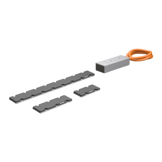
Page 20: Product Overview
Product overview 4 Product overview Number Explanation Primary part: coil part of the linear servomotor Thread for mounting on the machine slide Cable: power and temperature sensor Holes for locating pins Secondary part: Magnetic plate ─── AL8100 Version: 1.0.0... -
Page 21: Linear Servomotor
Peak force Continuous force Maximum velocity Protection class Peak current Continuous current Nominal voltage Insulation class cURus approval WEEE compliance Country of manufacture UKCA marking DataMatrix code; Beckhoff Identification Code (BIC) CE conformity EAC approval Hardware index Version: 1.0.0 AL8100 ───... -
Page 22: Type Key
Product overview 4.1.2 Type key AL8 t u v - w x y z - 0000 Explanation Product area Iron-core series 8 linear servomotors Series 1 = 48 V DC Overall width 2 = W2; 50 mm Overall length 1 = 3 2 = 6 4 = 12 6 = 18 Cooling... -
Page 23: Magnetic Plate
50 mm Made in Germany Item number Explanation Article name Order number Serial number Beckhoff Traceability Number (BTN) Length Width EAC approval CE conformity Country of manufacture Safety pictograms Barcode DataMatrix code; Beckhoff Identification Code (BIC) Version: 1.0.0 AL8100 ───... -
Page 24: Needle Pattern Marking
Product overview 4.2.2 Needle pattern marking Item number Explanation 10-digit serial number / 6-digit order number 8-digit Beckhoff BTN ─── AL8100 Version: 1.0.0... -
Page 25: Type Key
Product overview 4.2.3 Type key AL8 t u v - 0000 - 0000 Explanation Product area Iron-core series 8 linear servomotors Series 5 = magnetic plate Overall width 2 = W2; 50 mm Overall length 1 = short 2 = medium 3 = long Version: 1.0.0 AL8100... -
Page 26: Product Characteristics
Product overview 4.3 Product characteristics Dust-protected IP64 housing The coil parts are suitable for a wide range of environmental condi- tions. The coil parts and magnetic plates are fully potted and IP64 protected, making the components dustproof and suitable for tempo- rary immersion. -
Page 27: Ordering Options
Product overview 4.4 Ordering options 4.4.1 Connection cables The coil parts can be ordered either with pre-assembled connection cables and plugs or with open wire end sleeves. Plug The following plug variants are used, depending on the cable diame- ter: ®... -
Page 28: Intended Use
4.5.1 Improper use Any type of use that exceeds the permissible values from the techni- cal data is regarded as inappropriate and is thus prohibited. Beckhoff AL81xx linear servomotors are not suitable for use in the following situations: • Hazardous areas •... -
Page 29: Technical Data
Technical data 5 Technical data 5.1 Definition and technical terms This chapter provides information on various technical terms and their meaning. Consider validity framework All data valid for 40 °C ambient temperature and 60 K overtempera- ture of the winding. The data can have a tolerance of +/- 10 %. Peak force F Peak force at peak current I . -
Page 30: Data For Operation And Environment
Short-term or long-term operation outside of the specifications listed here may reduce the service life of the coil units. Beckhoff products are designed for operation under certain environ- mental conditions, which vary according to the product. The follow- ing specifications must be observed for operation and environment in order to achieve the optimum service life of the products. -
Page 31: Power Derating
Technical data 5.2.1 Power derating Derating may be necessary at high ambient temperature or when operating at a great height above sea level. Continuous forces are affected by the reduction. Ambient temperature = Temperature utilization factor = Ambient temperature in °C Calculation of the power data when exceeding the specified temper- ature limit >... -
Page 32: Al812X
Technical data 5.3 AL812x Performance data AL81xx 21-xE 21-xG 22-xE 22-xG 22-xJ 22-xN 24-xJ 24-xN 26-xN Peak force F [N] ; 3 s Peak current I Continuous force F [N] ; ΔT = 60 K Continuous current I Maximum nominal output voltage [V DC] Maximum velocity v [m/s]... -
Page 33: Dimensional Drawings
Technical data 5.3.1 Dimensional drawings • All figures in millimeters 5.3.1.1 AL8121 Version: 1.0.0 AL8100 ───... - Page 34 Technical data 5.3.1.2 AL8122 ─── AL8100 Version: 1.0.0...
- Page 35 Technical data 5.3.1.3 AL8124 5.3.1.4 AL8126 Version: 1.0.0 AL8100 ───...
-
Page 36: Al812X Alignment
Technical data 5.3.2 AL812x alignment Alignment based on AL812x as an example The figure shows the positioning of a coil unit in relation to the mag- netic track. ─── AL8100 Version: 1.0.0... -
Page 37: Al852X Magnetic Plates
Technical data 5.4 AL852x magnetic plates 5.4.1 Dimensional drawings • All figures in millimeters 5.4.1.1 AL8521 Version: 1.0.0 AL8100 ───... - Page 38 Technical data 5.4.1.2 AL8522 ─── AL8100 Version: 1.0.0...
- Page 39 Technical data 5.4.1.3 AL8523 Version: 1.0.0 AL8100 ───...
-
Page 40: Scope Of Supply
Check the shipment for the following contents: When ordering a coil unit: • AL8100 series coil unit • 2x adhesive name plates • Short information When ordering a magnetic plate: •... -
Page 41: Magnetic Plate
Scope of supply 6.1.2 Magnetic plate Symbol Explanation Devices that are sensitive to magnetic fields must be moved out of range. Warning: hand injuries. Persons with cardiac pacemakers are particularly at risk from the magnetic field. Persons with implants are particularly at risk from the magnetic field. -
Page 42: Transport And Storage
Transport and storage 7 Transport and storage NOTICE Avoid damage to the coil parts and resulting loss of war- ranty Observe the conditions and the following chapters on transport and storage. Failure to observe the conditions may result in damage to the coil parts and void the warranty. -
Page 43: Transport
Transport and storage 7.2 Transport WARNING Do not move under suspended loads Use suitable means of transport. Secure coil parts and magnetic plates against falling. Falling coil parts and magnetic plates can lead to serious or fatal accidents. NOTICE Do not touch connection points and plug contacts Ensure a protected working environment. -
Page 44: Long-Term Storage
Transport and storage 7.3 Long-term storage NOTICE Observe storage conditions Coil parts and magnetic plates can be stored for an unlimited pe- riod. Ensure that low air humidity is maintained when storing coil parts and magnetic plates. Failure to observe this may result in changes in the properties of the cables or the sealing compound. -
Page 45: Technical Description
Technical description 8 Technical description 8.1 Magnetic track length This chapter contains information on determining the length of the magnetic track. The necessary travel range is determined by the ap- plication specifications. The required magnetic path length corresponds to the travel range including the length of the coil part used. -
Page 46: Effective Calculation
Technical description 8.1.2 Effective calculation In an effective calculation, the travel path of the application is added to the length of the effective section of the coil unit and then divided by the length of the magnetic plate. Effective section The effective section contains are the coils of the coil unit. -
Page 47: Air Gap
Technical description 8.2 Air gap The air gap is created between the bottom of the coil part and the top of the magnetic plate. 8.2.1 Overall mounting height You can increase the overall mounting height and the associated air gap in case of tolerance deviations. Tolerance deviations can result from: •... -
Page 48: Dependencies
Technical description 8.2.2 Dependencies The following diagram shows the continuous force in relation to the attractive force as a function of the installation height: AL812x 100% 39 5 . 40 5 . 41 5 . 42 5 . 43 5 . 44 5 . -
Page 49: Protection Equipment
8.3 Protection equipment A temperature sensor LPTC-600 is installed in all coil parts of the AL8100 series. The LPTC-600 is integrated into the monitoring sys- tem of the servo terminals for motors with preassembled plugs. Con- figure the servo terminal according to the motor temperature warn- ing at 80 °C and the switch-off temperature at 100 °C. -
Page 50: Coupling
Coupling 9 Coupling NOTICE Ensure synchronization of coupled coil parts Ensure that the coupled coil parts move synchronously. Rigidly coupled coil parts can cause non-synchronous move- ments which can lead to tension and damage to the mechanical system and the coil part. NOTICE Only use parallel connection for coupling coil parts Coil parts should only be coupled in a parallel connection. -
Page 51: Shared Magnetic Track
Coupling 9.1.2 Shared magnetic track With this type of coupling, the coil parts are arranged one after the other on a common magnetic track. This type of coupling tends to be used for applications with long strokes, since a second magnetic track with associated costs is avoided. -
Page 52: Arrangement Of Coil Parts
Coupling 9.2 Arrangement of coil parts The coil parts must be arranged such that the distances shown in this chapter are adhered to. They thus guarantee the generation of a symmetrical rotary field and adhere to the minimum bending radius of the cables. -
Page 53: Cables Opposite
Coupling 9.2.3 Cables opposite This illustration shows an example of an arrangement of two coil parts with cables laid in opposite directions. The dimensions A - B - C are provided in the following tables. • A = minimum distance •... -
Page 54: Electrical Connection
Coupling 9.3 Electrical connection Wire the coupled coil units according to the phase offset. The wind- ings of the coil units always have the same winding distance to one another, which is dependent on the series. In the case of the AL8xxx series, the winding distance is 16 mm. -
Page 55: Offset Calculation
Coupling Example 2: AL8122 and AL8122 with cables in the same direc- tion With this alignment, observe the minimum bending radius of the mo- tor cables. 9.3.1 Offset calculation Carry out the wiring according to the arrangement of the coil units. You have to calculate the offset for the wiring. -
Page 56: Phase Lines
Coupling 9.3.2 Phase lines Motor [mm] AL8121 37.5 23.5 AL8122 39.5 23.5 AL8124 39.5 23.5 AL8126 39.5 23.5 ─── AL8100 Version: 1.0.0... -
Page 57: Power Supply
Coupling 9.3.3 Power supply With the calculated offset and using the following tables, you can carry out the wiring of the coupled coil parts. Cables in same direction Offset Cables in opposite directions Offset Cables to each other Offset 9.3.4 Temperature sensor By electrically connecting the coil parts in parallel to a servo termi- nal, only one temperature sensor can be connected. -
Page 58: Mechanical Installation
Mechanical installation 10 Mechanical installation All work should be carried out with great care and without time pres- sure. 10.1 Requirements When designing and dimensioning the machine or system, observe the basic requirements for the machine bed and the assembly of the coil part and magnetic plates. -
Page 59: Assembly
Mechanical installation 10.2 Assembly WARNING Warning of strong forces of magnetic attraction Avoid standing within the travel range of the coil part even when the machine or system is switched off. The permanent magnets of the magnetic plates and coils of the coil part attract each other. The high forces of magnetic attraction cannot be controlled by hand. -
Page 60: Coil Part
Mechanical installation 10.2.1 Coil part Loss of force due to asymmetry Place the coil unit of the AL812x series with an offset to the mag- netic plate. Failure to observe this may result in loss of force at the linear motor and loss of performance in the machine or system. - Page 61 Mechanical installation ► Place the assembled coil unit including the machine carriage [5] on the guide carriage [6] ► Insert and tighten the screws [7] Version: 1.0.0 AL8100 ───...
-
Page 62: Magnetic Plates
NOTICE Observe the alignment Align the magnetic plates identically. The Beckhoff logo must al- ways be on the same side. If this is not observed, the adjacent magnetic plates repel each other. As a result, the coil part cannot move without restriction. - Page 63 Maximum immersion in the mag- 3.2 mm netic plate ► Check the alignment of the magnetic plate. Make sure that the Beckhoff logos are on the same side. ► Place the magnetic plate [4] on the locating pins [3] Version: 1.0.0 AL8100...
- Page 64 Mechanical installation ► Insert screws [5] into the magnetic plate on the machine bed ► Tighten the screws crosswise and from inside to outside Observe tightening torque: Quality of the screws = strength class 8.8 Screw Tightening torque [Nm] ► Remove the protective cover [6] on the mounted magnetic plates onto which the machine slide is to be pushed.
-
Page 65: Verification
Mechanical installation 10.3 Verification After assembly, check the installed components for smooth running and adequate "air gap", [Page 47]. 10.3.1 Smooth operation Smooth running of the machine slide The machine slide should move smoothly along the entire magnetic track. A permanent air gap must exist between the coil part and the magnetic track. -
Page 66: Electrical Installation
11.1 Connection technology Beckhoff supplies pre-assembled power and feedback lines. For the selection of the cables required, refer to the Beckhoff documentation for the connecting cables. In the documentation you will find a com- plete overview of the available cables and information on the techni- cal data. -
Page 67: Connector Assignment
Electrical installation 11.2 Connector assignment Beckhoff offers various power connectors and feedback connectors. All plugs are IP65 rated. The following tables show the connector assignment: 11.2.1 iTec® plug Pin assignment cable diameter 1.0 mm² Contact Function Color Core identifi- cation Black... -
Page 68: Commissioning
• Check protective measures against moving and live parts Configuration Beckhoff recommends using Beckhoff servo terminals and motors and configuration with Beckhoff TwinCAT 3 Drive Manager 2 | TE5950. Carry out the instructions in the operating manual for servo termi- nals: •... -
Page 69: Prerequisites During Operation
Commissioning 12.3 Prerequisites during operation Pay attention to the following points during operation: • Pay attention to unusual noise developments • Always check drive surfaces and cables for dirt, leaks, moisture or dust • Check temperature development • Check for lubricant leakage •... -
Page 70: Maintenance And Cleaning
Maintenance and cleaning 13 Maintenance and cleaning WARNING Ensure safe condition for cleaning work Basically, electronic devices are not fail-safe. The condition is al- ways safe when the unit is switched off and not energized. For cleaning work, bring the connected motors and the machine into a safe state. -
Page 71: Decommissioning
Decommissioning 14 Decommissioning Disassembly may only be carried out by qualified and trained per- sonnel. Read the chapter Documentation notes. When disposing of electronic waste, make sure that you dispose of it in accordance with the regulations applicable in your country. Read and follow the instructions for proper disposal. -
Page 72: Disposal
In accordance with the WEEE-2012/19/EU directives, you can return used devices and accessories for professional disposal. The trans- port costs are borne by the sender. Send the used devices with the note "For disposal" to: Beckhoff Automation GmbH & Co. KG "Service" Building Stahlstrasse 31 D-33415 Verl... -
Page 73: Guidelines And Standards
Guidelines and Standards 15 Guidelines and Standards Test procedures and certifications vary by product. Beckhoff linear servomotors of the AL8100 series are certified and tested according to the following directives and standards. 15.1 Standards EN 60034-1:2010+Corr.:2010 "Rotating electrical machines – Rating and performance"... -
Page 74: Eu Conformity
15.5 CCC conformity Export to Chinese Economic Area Beckhoff linear motors of the AL8100 series are not subject to the China Compulsory Certificate; CCC. The products are exempt from this certification and can be exported to the Chinese economic area. - Page 76 More Information: www.beckhoff.com/al8100 Beckhoff Automation GmbH & Co. KG Hülshorstweg 20 33415 Verl Germany Phone: +49 5246 9630 info@beckhoff.com www.beckhoff.com...
Need help?
Do you have a question about the AL8100 Series and is the answer not in the manual?
Questions and answers