Table of Contents
Advertisement
Quick Links
Advertisement
Table of Contents

Related Manuals for HBM T10FM


Summary of Contents for HBM T10FM
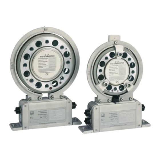
- Page 1 Mounting instructions Torque flange T10FM A0894-5.2 en...
-
Page 3: Table Of Contents
T10FM Contents Page Contents Safety instructions .......... - Page 4 T10FM Maintenance ..........
-
Page 5: Safety Instructions
T10FM Safety instructions Designated use The T10FM torque flange is used exclusively for torque and rotation speed measurement tasks, and directly associated control and regulatory tasks. Use for any additional purpose shall be deemed to be not as intended. In the interests of safety, the transducer should only be operated as described in the Operating Manual. - Page 6 Means that important information about the product or its handling is being provided. Symbol: Meaning: CE mark The CE mark enables the manufacturer to guarantee that the product complies with the requirements of the relevant EC directives (the Declaration of Conformity can be found at http://www.hbm.com/hbmdoc). A0894-5.2 en...
- Page 7 T10FM Symbol: Meaning: Statutory waste disposal mark In accordance with national and local environmental protection and material recovery and recycling regulations, old devices that can no longer be used must be disposed of separately and not with normal household garbage.
- Page 8 T10FM Accident prevention According to the prevailing accident prevention regulations, once the torque flange has been mounted, a covering agent or cladding has to be fitted as follows: The cover or cladding must not be free to rotate. The cover or cladding should avoid squeezing or shearing and provide protection against parts that might come loose.
-
Page 9: Scope Of Supply
Optional: Speed kit (slotted disc, screwdriver, screw locking device, screws) Application The T10FM torque flanges record static and dynamic torque on stationary or rotating shafts and determine the speed, specifying the direction of rotation. Test beds can be extremely compact because of their extremely short construction. -
Page 10: Structure And Mode Of Operation
T10FM Structure and mode of operation The torque flange consist of two separate parts: the rotor and the stator. The stator comprises an antenna ring and a housing. Strain gauges (SGs) are mounted on the rotor. The rotor electronics for transmitting the bridge excitation voltage and the measurement signal are located centrally in the flange. -
Page 11: Mechanical Installation
(medium strength) to exclude prestressing loss due to screw slackening. An appropriate shaft flange enables the T10FM torque flanges to be mounted directly. It is also possible to directly mount a joint shaft or relevant compensating element (see Fig.3.1) on flange B of the rotor (using an... -
Page 12: Conditions On Site
T10FM 4.1 Conditions on site T10FM torque flanges are protected to IP54 according to EN 60529. They must be protected against coarse dirt particles, dust, oil, solvents and humidity. During operation, the prevailing safety regulations for the security of personnel must be observed (see “Safety instructions"). -
Page 13: Installation Without Dismantling The Antenna Ring
T10FM 4.3.1 Installation without dismantling the antenna ring Customer mounting 2. Install stator 1. Install rotor Support supplied by customer Clamp fixture 4. Mount the clamp fixture where 3. Finish installation of shaft train required A0894-5.2 en... -
Page 14: Installation With Subsequent Stator Mounting
T10FM 4.3.2 Installation with subsequent stator mounting Customer stator mounting 1. Install rotor 2. Install shaft train 3. Remove one antenna segment 4. Install antenna segment around shaft train Support supplied by customer Clamp fixture 5. Align stator and finish installation 6. -
Page 15: Preparing For The Rotor Mounting
T10FM 4.4 Preparing for the rotor mounting IMPORTANT The rotor is very heavy (depending on measuring range: 26 kg ... 60 kg)! Use a crane or other suitable lifting equipment to lift it out of its packaging and install it. - Page 16 T10FM 1. Lift the rotor out of the packaging, rotate horizontally by 10_, so that flange B is pointing upwards (see Fig. 4.2). Flange B Fig. 4.2: Rotating the rotor 2. Place the rotor carefully onto a clean and stable table.
-
Page 17: Mounting The Rotor
T10FM Fig. 4.3: Rotor installation (horizontal) 4.5 Mounting the rotor IMPORTANT For correct operation, comply with the mounting dimensions (particularly the area free of metal, see Page 44). Additional installation notes for the speed measuring system can be found in Chapter 4.8, Page 24. - Page 18 T10FM Hexagon socket screw (Z) DIN EN ISO 4762 (10.9) Fastening screws (10.9); note maximum screw‐in depth Y! Flange A Fig. 4.4: Screwed rotor joint 1. For the connection of flange A (see Fig. 4.4), use DIN EN ISO 4762 property class 10.9 hexagon socket screws of a suitable length...
- Page 19 T10FM 4. There are relevant tapped holes on flange B for continuing the shaft run mounting. Again use screws of property class 10.9 and tighten them with the prescribed torque, as specified in Table 4.1. IMPORTANT With alternating loads, use a screw locking device to cement the connecting screws into place! Guard against contamination from varnish fragments.
-
Page 20: Installing The Stator
T10FM 4.6 Installing the stator On delivery, the stator has already been installed and is ready for operation. The antenna segments can be separated from the stator, for example, for maintenance or to facilitate stator mounting. To stop you modifying the center alignment of the segment rings opposite the base of the stator, we recommend that you separate only one antenna segment from the stator. - Page 21 T10FM 1. Loosen and remove the screw fittings (M5) on one antenna segment. Make sure that the fan‐type lock washers are not lost! 2. Use an appropriate base plate to install the stator housing in the shaft train so that there is sufficient possibility for horizontal and vertical adjustments.
-
Page 22: Installing The Clamp Fixture
T10FM 4.7 Installing the clamp fixture Depending on the operating conditions, oscillations may be induced in the antenna ring. This effect depends on the speed the antenna diameter (depends in turn on the measuring range) the design of the machine base To avoid vibrations, a clamp fixture with extension is enclosed with the torque flange enabling the antenna ring to be supported. - Page 23 T10FM Support supplied by the customer, e.g. threaded rod Clamp fixture Extension Fan‐type lock washers Antenna segments Fig. 4.7: Installing the clamp fixture Important Use, e.g. plastic as the material. Do not use metallic material as this can affect the function of the antenna (signal transmission).
-
Page 24: Fitting The Slotted Disc (Speed Measuring System)
T10FM 4.8 Fitting the slotted disc (speed measuring system) To prevent damage to the speed measuring systems' slotted disc during transportation, it is not mounted on the rotor. Before installing the rotor in the shaft run, the customer must attach it to the intermediate flange. The intermediate flange and the associated speed sensor are already mounted at the factory. -
Page 25: Aligning The Stator (Speed Measuring System)
T10FM 4.9 Aligning the stator (speed measuring system) The stator can be mounted in any position (for example, “upside down" installation is possible). For perfect measuring mode, the slotted disc of the speed measuring system must rotate at a defined position in the sensor pickup. - Page 26 T10FM NOTE To attach the stator, we recommend the use of M6 screws with plain washers (width of oblong hole, 9 mm). This size of screw guarantees the necessary travel for alignment. Radial alignment The rotor axis and the optical axis of the speed sensor must be along a line at right angles to the stator platform.
-
Page 27: Electrical Connection
Avoid transformers, motors, contactors, thyristor controls and similar stray‐field sources. IMPORTANT Transducer connection cables from HBM with attached connectors are identified in accordance with their intended purpose (Md or n). When cables are shortened, inserted into cable ducts or installed in control cabinets, this identification can get lost or become concealed. -
Page 28: Connector Pin Assignment
IMPORTANT These torque flanges are only intended for operation with a DC supply voltage. They must not be connected to older HBM amplifiers with square‐wave excitation. This could lead to the destruction of the connection board resistances or other errors in the measuring amplifiers (the torque flange, on the other hand, is protected and once the proper connections have been re‐established, is ready for operation... - Page 29 T10FM Assignment for connector 2: Speed measuring system. Conn. Assignment Wire Sub‐D color Binder Conn. Speed measurement signal (pulse string, 5 V 0) No function Binder 723 Speed measurement signal (pulse string, 5 V 90 out‐of‐phase) No function No function Speed measurement signal (pulse string, 5 V 0)
-
Page 30: Supply Voltage
Connect a separated extra‐low voltage of 18 V...30 V to pin 3 (+) and pin 2 ( ) of connectors 1 or 3. We recommend that you use HBM cable KAB 8/00-2/2/2 and the relevant Binder sockets, that at nominal (rated) voltage (24 V) can be up to 50 m long and in the nominal voltage range, 20 m long (see Accessories, page 45). -
Page 31: Calibration Signal
T10FM Calibration signal The T10FM torque flange delivers an electrical calibration signal that can be switched at the amplifier end for measurement chains with HBM components. The measurement flange generates a calibration signal of about 50 % of the nominal (rated) torque. The precise value is specified on the type plate. Adjust the amplifier output signal to the calibration signal supplied by the connected torque flange to adapt the amplifier to the measurement flange. -
Page 32: Settings
T10FM Settings NOTE You will find a table containing all the relevant switch positions on the back of the stator cover. Changes to the factory settings should be noted here using a waterproof felt‐tip pen. Einstellungen / Settings OPTION 4... -
Page 33: Setting Up The Zero Point
T10FM 12 V symmetrical asymmetrical Pos.2 Pos.1 Fig. 7.2: Switch for changing the frequency output voltage 7.2 Setting up the zero point You can access two potentiometers by removing the stator cover. You can use the zero point potentiometer to correct zero point deviations caused by the installation. -
Page 34: Functional Testing
T10FM 7.3 Functional testing 7.3.1 Power transmission If you suspect that the transmission system is not working properly, you can remove the stator cover and test for correct functioning. If the LED is on, the rotor and stator are properly aligned and there is no interference with the transmission of measurement signals. -
Page 35: Setting The Pulse Count
T10FM IMPORTANT When closing the cover of the stator housing, make sure that the internal connection cables are positioned in the grooves provided and are not trapped. 7.4 Setting the pulse count The number of pulses per revolution of the rotor in the speed module option can be adjusted by means of DIP switches S1...S4. -
Page 36: Vibration Suppression (Hysteresis)
T10FM 7.5 Vibration suppression (hysteresis) Low rotation speeds and higher relative vibrations between the rotor and the stator can cause disturbance signals that reverse the direction of rotation. Electronic suppression (hysteresis) to eliminate these disturbances is connected at the factory. This suppresses disturbances caused by radial stator vibration displacement of approx. - Page 37 T10FM Direction of rotation arrow Fig. 7.8: Direction of rotation arrow on the head of the sensor Doubling the pulses Switch S6 Fig. 7.9: Switch for doubling the pulses A0894-5.2 en...
-
Page 38: Type Of Speed Output Signal
T10FM 7.7 Type of speed output signal You can use switch S7 to change the symmetrical 5 V output signal (factory setting) to an asymmetrical signal of 0 V ... 5 V. symmetrical asymmetrical Switch S7 Pos.2 Pos.1 Fig. 7.10: Switch S7; symmetrical/asymmetrical output signal... -
Page 39: Loading Capacity
The torque flanges can be used to measure static and dynamic torques. The following rule applies to the measurement of dynamic torque: The T10FM calibration made for static measurements is also valid for dynamic torque measurements. The natural frequency f... - Page 40 T10FM 100% Oscillation width 100% Fig. 8.1: Permissible dynamic loading A0894-5.2 en...
-
Page 41: Maintenance
T10FM Maintenance The torque flanges without a speed module are maintenance‐free. 9.1 Speed module maintenance During operation and depending on the ambient conditions, the slotted disc of the rotor and the associated stator sensor optics can get dirty. This will become noticeable when the polarity of the display changes. -
Page 42: Dimensions
T10FM Dimensions 10.1 Dimensions without speed measuring system View Y View X Thread Y turned ød cutting plane ødA Thread Y L max. = measuring plane (center of the application poin Measuring Dimensions (in mm; 1 mm = 0.03937 inches) range (kNVm) d... -
Page 43: Dimensions With Speed Measuring System
T10FM 10.2 Dimensions with speed measuring system View Y View X Slotted disc Thread Y turned 0.3 thick the cutting (installed by the plane customer) Through hole Fastening screws Thread Y slotted disc L max. Supplementary disc for slotted disc... -
Page 44: Mounting Dimensions
T10FM 10.3 Mounting dimensions Mounting dimensions Measuring range Area a free of metal parts (kNVm) (mm) Rotor identification d plate *) Support with metal rod is permissible with the recommended dimensions Stator identification plate A0894-5.2 en... -
Page 45: Order Numbers, Accessories
T10FM Order numbers, accessories Code Option 4: Speed measuring system Code Option 1: Measuring range No speed measuring system 015R 15 kNm With speed measuring system 020R 20 kNm 025R 25 kNm 030R 30 kNm 040R 40 kNm 045R 45 kNm 050R 50 kNm... -
Page 46: Specifications
T10FM Specifications Type T10FM Accuracy class Torque measuring system Nominal (rated) torque M kNm 15 40 45 50 60 70 Nominal (rated) sensitivity (nominal (rated) signal range between torque = zero and nominal (rated) torque) Frequency output Voltage output Sensitivity tolerance (deviation of... - Page 47 T10FM Nominal (rated) torque M kNm Temperature effect per 10 K in the nominal (rated) temperature range on the output signal, related to the actual value of the signal spread Frequency output <"0.1 Voltage output <"0.2 on the zero signal, related to the...
- Page 48 T10FM Speed measuring system Nominal (rated) torque M kNm Measurement system Optical, by means of infrared light and metallic slotted disc Mechanical increments Positional tolerance of the increments "0.05 Slot width tolerance "0.05 Pulses per revolution Electrically adjustable ; 360; 180; 90; 60; 30; 15 Output signal symmetrical;...
- Page 49 T10FM General Information Nominal (rated) torque M kNm Emission (as per EN 61326-1, Table 4) RFI field strength Class B Interference immunity (EN 61326-1, Table A.1) Electromagnetic field (AM) Magnetic field Electrostatic discharge (ESD) Contact discharge Air discharge Rapid transients (burst)
- Page 50 T10FM Nominal (rated) torque M kNm Nominal (rated) 6000 4000 3000 speed Load limits Limit torque kNm Breaking torque kNm >50 >90 >160 Longitudinal limit force Lateral limit force Bending limit moment Nm 6000 12000 24000 Vibration bandwidth per DIN 50 100 (peak/...
- Page 51 T10FM Mechanical values 50 kNVm ... 80 kNVm Nominal (rated) torque M kNm Torsional stiffness c kNm/ 60000 Torsion angle at M Deg. 0.05 0.06 0.07 0.08 Maximum deflection at longitudinal force limit < 0.12 Additional max. radial run‐out deviation at lateral limit force <...
-
Page 52: Supplementary Technical Information
T10FM Supplementary technical information 13.1 Output signals 13.1.1 Output MD torque (connector 1) Symmetrical output signals (factory setting) symmetrical Pos.2 Connector 1 10 Vpp Differential inputs Asymmetrical output signal 12 V asymmetrical Pos.1 Connector 1 A0894-5.2 en... -
Page 53: Output N Speed (Connector 2)
T10FM 13.1.2 Output N Speed (connector 2) Symmetrical output signals (factory setting) Connector 2 symmetrical Pos.2 Switch S7 10 V Differential 10 V inputs Asymmetrical output signal asymmetrical Connector 2 Switch S7 Pos.1 A0894-5.2 en... -
Page 54: Output Speed, Double Frequency, Stat. Direction Of Rotation Signal
T10FM 13.1.3 Output speed, double frequency, stat. direction of rotation signal Direction of Direction of rotation rotation in against direction of direction of the arrow the arrow Connector 2 10 V 10 V A0894-5.2 en... -
Page 55: Axial And Radial Run-Out Tolerances
T10FM 13.2 Axial and radial run‐out tolerances 0.04 AB 0.04 AB Internal centering Hardness 46 ... 54 HRC Flange A Flange B Surface quality of the run‐out and concentric surfaces (A, B and AB) 13.3 Additional mechanical data Measuring range kNm... - Page 56 They are not to be understood as express warranty and do not constitute any liability whatsoever. Hottinger Baldwin Messtechnik GmbH Im Tiefen See 45 S 64293 Darmstadt S Germany Tel. +49 6151 803-0 S Fax: +49 6151 803-9100 Email: info@hbm.com www.hbm.com...
Need help?
Do you have a question about the T10FM and is the answer not in the manual?
Questions and answers