
Related Manuals for Thermo Scientific Orion 8030cX


Summary of Contents for Thermo Scientific Orion 8030cX
- Page 1 Orion 8030cX Silica Analyzer Instruction Manual Version C, Feb 2022 Before using the instrument, please read this Instruction Manual carefully!
-
Page 2: Table Of Contents
Contents Chapter 1 ........................1 Safety Measures ...................... 1 Chapter 2 ........................3 Brief Introduction of Application Fields ..............3 Specifications ......................3 Instrument Size ......................5 Fundamental Principles .................... 7 Chapter 3 ........................8 Unpacking Inspection ....................8 Requirements for Instrument Installation ..............8 Flow Cell ........................ -
Page 3: Chapter 1
Basic Information This manual provides the operation, maintenance, troubleshooting and other contents of Thermo Scientific Table 1.1: Safety Precautions Orion 8030cX Silica Analyzer. Please read this manual completely before installing and operating this equipment. This symbol, when noted on Electric Shock... - Page 4 5. After installation, ensure that all vent holes of used bottles are unblocked. 6. Ensure that you have obeyed applicable specifications for accident Warning prevention. Substances shall disposed of in accordance with applicable local laws and regulations. This symbol, when noted on the product, identifies the Grounding Warning...
-
Page 5: Chapter 2
Thermo Fisher Scientific Inc. Specifications Table 2.1: Specifications of Orion 8030cX Silica Analyzer 0-5000 µg/L Range of measurement Auto-switching between two sub-ranges (0-1000 µg/L and 1000-5000 µg/L) - Page 6 Housing protection class IP65 450 mm × 791 mm × 320 mm (17.7in × 31.1in × 12.6in) Instrument size (W × H × D) Instrument installation 41kg (90 lbs) Transportation weight 26.8kg ( 59.1 lbs ) Instrument weight Electronic Requirements for power 100–240VAC, 100W, 50/60Hz parameters supply...
-
Page 7: Instrument Size
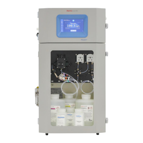
Instrument Size Figure 2.1: Size of 8030cX Silica Analyzer (Unit: mm) 8030cX Silica Analyzer Product Overview Chapter 2 | 5... - Page 8 Flow cell Electronic Cabinet Standards, Reagents, Clean Solution, Validation USB port solution bottles Fluidic Touch screen panel Signal line hole Figure 2.2: Main Interactive Interface of 8030cX Silica Analyzer 6 | Chapter 2 Product Overview 8030cX Silica Analyzer...
-
Page 9: Fundamental Principles
(PLC or DCS) through 0/4-20 mA output signals or RS485. The user can set the Orion 8030cX Silica Analyzer is based on the detection measurement time, measurement frequency, calibration, principle of the Heteropoly-molybdenum blue colorimetric cleaning and validation frequency according to the site- method. -
Page 10: Chapter 3
Installation Unpacking Inspection Requirements for Instrument Installation Orion 8030cX Silica Analyzer has been carefully tested and packaged before leaving the factory. Basic Requirements for Instrument Installation Open the inner and outer packing and check the product Instructions for instrument handling: and accessories according to the Packing Checklist. - Page 11 topple if it is not properly fastened. In the cold climate, it is recommended that the silica analyzer be installed in a non-freezing indoor environment. Select the installation location as close as possible to the water sample source, which can reduce the sample delay as much as possible.
- Page 12 • Note: During installation, especially when for your wastewater facility to handle or meet your installing external cables, do not discard the discharge regulation. rubber seal covers on the side of the instrument. External cables need to pass through these rubber seal covers to enable the IP65 protection.
- Page 13 Mounting Methods of the Instrument Before Installation, select a suitable wall for installing expansion screws, the wall surface has enough load capacity (at least 4 times weight of the instrument is required). If the instrument is damaged because it is not mounted firmly, Thermo Fisher will not assume any responsibility.
-
Page 14: Flow Cell
Option 2: Used the Expansion Bolts to Fix the the other is 6 mm OD or ¼ inch OD (7). (Figure 3.4) Instrument Expansion Spring 1 8030cX Silica Analyzer 4 Washer(4pcs) M6*80 Expansion Expansion Nut (4pcs) Screw (4pcs) Expansion Plain Installation Wall Washer (4pcs) Figure 3.3: Expansion Bolts to Fix the Instrument... - Page 15 The entire flow cell is mounted on the outside cabinet wall of the 8030cX Silica Analyzer with two M4 x 40 mm screws, as shown in Figure 3.4. Figure 3.5: Flow Cell Installation Position Note: Item Specification Name Quantity • The inlet port in Flow cell is connected to the Flow cell body common port in the sequencer (if used) and the...
-
Page 16: Optional Sample Inlet Filter
5. Insert the end of the overflow drain tube to the 2. Loosen the nut on the large straight joint, then correct drain location, secure the tubing if needed insert the larger overflow tubing (16 mm OD), to prevent slip off. which sends sample overflow to drain. -
Page 17: Electronic Connection
After installation, the water sample filtered by the prefilter goes to the flow cell as shown in the graph below from left to right. Connecting source water to Y-strainer to adaptor, 6mm (or Figure 3.6: Main Interfaces of Main Control Board ¼") OD soft tubing, and flow cell. - Page 18 • Insert the wire into the corresponding wiring terminal and tighten the screw. • The signal wire passes through the threading conduit on the left, and the power cord passes through the threading conduit on the right. • All connections must be conformed to local safety standards.
- Page 19 Connection of Power Cord • The instrument is equipped with power wiring terminals in the electronic box (see Figure 3.9 and Table 3.1). • It is strongly suggested that the user shall install an external power switch or a circuit breaker (with GFCI protection) for the instrument to facilitate the operator to control.
- Page 20 pin 1 and pin 2 of J1 provide a 24V DC power supply. Table 3.2: J4 and J5 Wiring Terminals Please refer to Figure 3.13 for specific digital power Con- Termin- access. Please refer to Table 3.4 for digital signal input Name Description nector...
- Page 21 Knotting of External Wiring All external wiring shall be knotted near the rubber sealing cover in the cabinet, otherwise the cables will be pulled, which would cause damage to the wiring terminals on the Figure 3.15: RS485 Communication Signal Wiring circuit board.
-
Page 22: Chapter 4
Chapter 4 System Startup • Do not power on the instrument before completing the Ensure compliance with applicable local accident preparation of reagents, water samples, standard prevention laws and regulations. solutions, validation solution, and cleaning solution. • Properly dispose of all chemicals and obey applicable local laws and regulations. - Page 23 Reagent 1 Standard solution 1 bottle bottle Reagent 2 Standard solution 2 bottle bottle Reagent 3 Clean waste bottle/tank bottle Validation solution Chemical waste bottle/ bottle tank Deep clean solution Sampling tube bottle Figure 4.1 Reagents, Standard Samples, and Cleaning Solutions Installation Table 4.1: Electronic rotary valve (ERV) Port and its Port Connection Installation Direction of Electronic...
- Page 24 • 4. Insert the small reagent/solution tube attached to The length of main tubing R1, R2 and R3 should the analyzer into the guide tube, the end of the be controlled within a certain range, and it is small reagent/solution tube must exceed the end suggested not to exceed 1.0 meter.
-
Page 25: Instrument Startup
difficulties in discharge of wastes, which will affect Installation of Clean Waste Tank, Chemical the performance of the instrument. Waste Tank, or Drain Connections • The waste tank must be clearly marked and Please refer to Figure 4.1 regarding waste tubing. managed in accordance with local laws and The instrument has two liquid waste tubing for discharging regulations. - Page 26 The reagents, standard, and cleaning solution will self- prime during analysis under default settings. 24 | Chapter 4 System Startup 8030cX Silica Analyzer...
-
Page 27: Chapter 5
Chapter 5 System Running Menu Interface Tree The operation interface of Orion 8030cX Silica Analyzer is simple and easy to understand. The menu structure is as follows: Automatic Silica Analyzer Manual Setup Settings Mai nt enance Operat ion Initialization/ Connecti... -
Page 28: Return
The return key of the navigation bar is used to return from the current page to the previous one. The main interface navigation bar is used to return to the main interface from Figure 5.3: Main Interface of Orion 8030cX Silica any of sub-pages. Analyzer in Case of Alerts... - Page 29 Prime Volume is set according to the sample tubing length. Measurement Setup This function is used to rinse the sample tubing with the The Measurement Setup is used to configure analysis freshwater sample to ensure measurement accuracy. The parameters such as Mode (Manual/ Interval /Continuous), prime volume can be calculated with the following Range, Method, Auto Range, Reaction Time, Reaction Equation:...
- Page 30 The fresh sample is primed into the sample tubing with the volume of Prime Prime Volume Volume configured to rinse sample tubing. The Default is set to 1.2mL. 28 | Chapter 5 System Running 8030cX Silica Analyzer...
- Page 31 Mode, Calibration Points, Standard Concentration(s), Action Calibration Setup When Fails and Calibration Tolerance (Slope and Intercept), Calibration Setup is used to configure calibration shown in the Table 5.2. parameters including Calibration Range, Calibration Table 5.2: Definition of Calibration Parameters Calibration Parameters Sub-options Definition of Parameter The Calibration Range of 0 µg/L~ 1000 µg/L is for low range;...
- Page 32 Table 5.3: Definition of Validation Parameters Validation Sub-options Definition of Parameter Parameters Manual The instrument is validated once when validation is started. The instrument is validated automatically with an interval (such as 24 hours) Mode Interval when Validation Mode of Interval is selected. The Interval default is set to 168 hours (1 week).
- Page 33 operating modes include Alarm and Event. More details Relay Setup includes the On-Off setting and operating shown in table 5.4. mode setting. When Relay Setup is “ On ” the available Table 5.4.1: Definition of Relays Setup Relays Setup Parameters Sub-options Definition of Parameter Default setting is Off.
-
Page 34: Log
instrument. Digital Inputs: digital signals can be wired into the analyzer as inputs, which are used to turn the functions ON/OFF with preset delay. Functions include Measurement, Deep Clean, Calibration, Validation and Abort or None. When they are set to the corresponding function, the corresponding function is started when there is an input. -
Page 35: Settings
Measurement Log Application version. Access control is used in login interface, and is used for users with different permissions Measurement log is used to view and export to log in. measurement results, including the measurement time, date, and measurement details, etc. Click the detailed Connectivity information each... - Page 36 Manual Operation Orion 8030cX Silica Analyzer provides users with the following Manual Operation menus: Measurement, Calibration, Validation, Deep Clean, Clean operation, Drain Cell, Prime, and Air Flush.
- Page 37 Manual Operation Deep Drain Measurement Calibration Validation Clean Prime Clean Cell Flush being used match the concentration settings for Standard Measurement 1 Conc.(Default is 20 µg/L) and Standard 2 Conc. (Default Click "Start" to run measurements according to the is 200 µg/L). If calibration points is set to single, Standard 1 configured parameters.
- Page 38 If clean needs to be stopped, click the "Stop" button, but can be performed automatically using the settings in this operation is not recommended. Special cleaning Setup-Validation Setup menu. In the “ Action When Fails ” “ Calibrate ” . setting, select After...
- Page 39 Recommend switching to horizontal text and better Temperature sensor calibration is used to calibrate the reaction temperature. If there is a deviation in the reaction resolution text. (Leave this to be done in formatting process) temperature, calibration of the temperature sensor can be conducted by a service technician.
- Page 40 Peristaltic Pump 1: It includes pump speed setting and System Management pump rotation setting; the speed unit is rps (rotations per second). Click "Execute" to execute according to the set System management includes Restoring Factory Settings, parameters. Software Upgrade, Remain Reagent Volume and Tubing Life.
-
Page 41: Chapter 6 | 39
Chapter 6 Regular Maintenance The enclosure of Orion 8030cX Silica Analyzer has a Regular Maintenance security lock, which can only be unlocked by a key. After it Table 6.1: Regular Maintenance is unlocked, you can replace reagents, and carry out Professional related regular maintenance work. -
Page 42: Liquid Leakage Maintenance
fluidic system. After deep cleaning, an instrument Note: calibration is needed to correct the instrument reading bias. 1. After replacing the sample tubes, the prime Liquid Leakage Maintenance volume of the water sample needs to be adjusted according to the length of the sample tubes. The instrument has the function of liquid leakage alarm to 2. -
Page 43: Long-Term Idle
Long-term Idle Step 3: Insert all tubing (reagent 1, reagent 2, reagent 3, standard sample, water sample and cleaning solution) into If the instrument is in idle status for a long time (running DI water container. only once a day or even less), in order to prevent the crystallization of residues or sediment of other particulates Step 4: Perform the manual prime procedure twice or more in the instrument tubing and especially in the electronic... -
Page 44: Chapter 7
Chapter 7 Common Errors and Troubleshooting Measures Warning ! Alerts and alarms information will be displayed in the main interface ’ s history records - alert and alarm information. Only trained qualified service personnel can maintain the equipment! Reagents in the instrument are corrosive! Table 7.1: Alerts Information and Troubleshooting Methods Troubleshooting Alerts Information... - Page 45 Troubleshooting Alerts Information Methods 1. Enter Hardware Calibration menu to perform calibration of Analog Output, Optics, and Liquid Sensor. EEPROM failed, default 2. If the alert persists after calibration of all hardware, it may be a circuit board loaded hardware failure or a software problem, please contact service personnel for maintenance or replacement.
- Page 46 Table 7.2: Alarms Information and Troubleshooting Methods Troubleshooting Alarms Information Methods 1. Stop measurement and enter the Maintenance-Diagnostics-Heater menu to observe the temperature of the reaction/measurement cell. The temperature change of the Heater loses control reaction/measurement cell should be within ± 1 ° C. 2.
- Page 47 Troubleshooting Alarms Information Methods 1. Shutdown the instrument, remove the LED0 and PD0, and observe whether there are obstructions, dirt, or debris in the light path. If obstructions are observed, use cotton swabs dipped in alcohol to clean the LED & PD. 2.
- Page 48 Troubleshooting Alarms Information Methods 1. Check the liquid level in the cleaning solution bottle. 2. Ensure that the cleaning solution tubing is fully inserted and touches the bottom of the cleaning solution bottle. 3. Prime the cleaning solution and look to see if back flow occurs at the place where the Lack of clean cleaning solution tubing is connected to port 1 of the electronic rotary valve (ERV);...
- Page 49 Troubleshooting Alarms Information Methods 1. Check the liquid level in reagent 3. 2. Ensure that the tubing for reagent 3 is fully inserted and touches the bottom of the reagent bottle. 3. Prime reagent 3 solution and look to see if back flow occurs at the place where the Lack of reagent 3 reagent 3 solution tubing is connected to port 5 of the electronic rotary valve (ERV);...
- Page 50 Troubleshooting Alarms Information Methods 1 Check the liquid level in the validation solution. 2 Ensure that the tubing for the validation solution fully inserted and touches the bottom of the validation solution bottle. 3 Prime the validation solution and look to see if back flow occurs at the place where the Lack of validation validation solution tubing is connected to port 10 of the electronic rotary valve (ERV);...
- Page 51 Troubleshooting Alarms Information Methods 1. If calibration fails, enter Setup-Calibration Setup menu to check whether the Range, Tolerance, the Standard 1 Conc. and Standard 2 Conc. are setup properly. 2. Check that the correct standard sample 1 and sample 2 bottles are connected to the appropriate tubing.
-
Page 52: Chapter 8
Chapter 8 Customer Service Part List (Accessory) Compliance Precautions This equipment could generate and radiate radio Silica Analyzer frequency energy. If not installed and used according to Model the Instruction Manual, it may cause interference to radio Part Number Description Name communication. - Page 53 due to any of the above reasons, the order delivery date or Dangerous Goods fulfillment completion time shall be reasonably extended for a period to cope with the impact of the delay. Some materials are corrosive/oxidizing reagents specified by DOT and IATA and may require special marks and Warranty handling.
- Page 54 Except for the terms of this warranty, any inconsistent statement and warranty made by any person (including authorized distributors, dealers, representatives and employees of the manufacturer) shall not be binding on the manufacturer, unless the written consent or signature of an official from the manufacturer has been gained. 52 | Chapter 8 Customer Service 8030cX Silica Analyzer...
- Page 55 Manufacturer: Thermo Fisher Scientific (Suzhou) Instruments Co., Ltd. Thermo Fisher Scientific Address: No 555, Jinfeng Road, Suzhou, Jiangsu, China thermoscientific.com/water © 2015 Thermo Fisher Scientific Inc. All rights reserved. Modbus is a registered trademark of Schneider Electric. All other trademarks are the property of Thermo Fisher Scientific Inc.
Need help?
Do you have a question about the Orion 8030cX and is the answer not in the manual?
Questions and answers
NEED INFORMATION ON THE PERISTALTIC PUMP FOR THIS 80360CX ANALYZER
The Thermo Scientific Orion 8030cX analyzer includes two peristaltic pumps:
- Peristaltic Pump 1: Allows setting of pump speed and rotation. Speed is measured in rotations per second (rps). Click "Execute" to run based on the set parameters.
- Peristaltic Pump 2: Also allows setting of pump speed and rotation, with speed in rps. Click "Execute" to run based on the set parameters.
This answer is automatically generated