Table of Contents
Advertisement
Quick Links
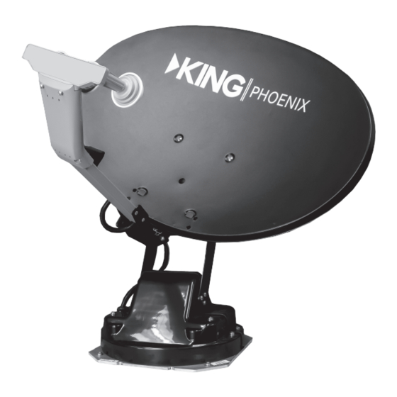
KPD1000 (DISH) • KPT1000 (DIRECTV)
This Owner's Manual contains detailed installation and operating instructions.
see the Quick Reference Guide to start using your KING Phoenix right away.
INSTALLATION MATERIALS SUPPLIED BY INSTALLER . . . . . . . . . . . . . . . . . . . . 2
ANTENNA UNIT ASSEMBLY . . . . . . . . . . . . . . . . . . . . . . . . . . . . . . . . . . . . . . . . . 2-6
UNPACK AND VERIFY COMPONENTS . . . . . . . . . . . . . . . . . . . . . . . . . . . . . . . . 2
RAISE ARM FOR DISH INSTALLATION . . . . . . . . . . . . . . . . . . . . . . . . . . . . . . . . 3
ATTACH DISH AND ARM TO BASE MOUNT . . . . . . . . . . . . . . . . . . . . . . . . . . . . . 4
DISH: LNB INSTALLATION . . . . . . . . . . . . . . . . . . . . . . . . . . . . . . . . . . . . . . . . 5-6
DIRECTV: LNB INSTALLATION . . . . . . . . . . . . . . . . . . . . . . . . . . . . . . . . . . . . . 5-6
CONNECT LED LIGHT (OPTIONAL) . . . . . . . . . . . . . . . . . . . . . . . . . . . . . . . . . . . 6
INSTALLATION . . . . . . . . . . . . . . . . . . . . . . . . . . . . . . . . . . . . . . . . . . . . . . . . . . . 7-15
DETERMINE ROOF LOCATION . . . . . . . . . . . . . . . . . . . . . . . . . . . . . . . . . . . . . . 8
MOUNT THE UNIT . . . . . . . . . . . . . . . . . . . . . . . . . . . . . . . . . . . . . . . . . . . . . . . . . 9
MOUNT THE STOW PLATE . . . . . . . . . . . . . . . . . . . . . . . . . . . . . . . . . . . . . . . . . . 9
ROUTE WIRING . . . . . . . . . . . . . . . . . . . . . . . . . . . . . . . . . . . . . . . . . . . . . . . 10-11
MAKE INTERIOR CONNECTIONS . . . . . . . . . . . . . . . . . . . . . . . . . . . . . . . . 12-15
OPERATION . . . . . . . . . . . . . . . . . . . . . . . . . . . . . . . . . . . . . . . . . . . . . . . . . . . . 16-18
MOVING THE DISH MANUALLY . . . . . . . . . . . . . . . . . . . . . . . . . . . . . . . . . . . . . . . 19
KING LIMITED WARRANTY . . . . . . . . . . . . . . . . . . . . . . . . . . . . . . . . . . . . . . . . . . . 20
FCC GUIDELINES . . . . . . . . . . . . . . . . . . . . . . . . . . . . . . . . . . . . . . . . . . . . . . . . . . . 21
If the KING Phoenix is already installed,
CONTENTS
Owner's Manual
Advertisement
Table of Contents

Related Manuals for KING PHOENIX KPD1000


Summary of Contents for KING PHOENIX KPD1000
-
Page 1: Table Of Contents
This Owner’s Manual contains detailed installation and operating instructions. If the KING Phoenix is already installed, see the Quick Reference Guide to start using your KING Phoenix right away. CONTENTS INSTALLATION MATERIALS SUPPLIED BY INSTALLER . . . . . . . . . . . . . . . . . . . . 2 ANTENNA UNIT ASSEMBLY . -
Page 2: Installation Materials Supplied By Installer
• Appropriate tools and fasteners to install all components and wiring ANTENNA UNIT ASSEMBLY UNPACK AND VERIFY COMPONENTS 1 . The KING Phoenix was shipped in two boxes . Open the boxes and verify all parts are present . BOX 1 • Base mount assembly •... -
Page 3: Raise Arm For Dish Installation
You can do the assembly steps on pages 3-6 on the ground or on the roof . You may find it easier to take the components up to the roof before assembly. RAISE DISH ARM TO INSTALL DISH ASSEMBLY 1 . Place the base mount on a stable and level work surface . 2 . -
Page 4: Attach Dish And Arm To Base Mount
ATTACH DISH AND ARM TO BASE MOUNT 1 . Feed coax (inside the split loom) thru the hole in the dish, from back to front . 2 . Attach the dish to the mounting brackets on the base mount using the top two holes and supplied washers and screws (1/4”-20 x 3/4”... -
Page 5: Dish: Lnb Installation
DISH: DIRECTV: LNB INSTALLATION LNB INSTALLATION 1 . Fasten (2) stow brackets to arm brackets 1 . Remove and save (2) inner screws from with (2) screws on each side . LNB bracket . 2 . Loosen, but do not remove, (2) outer screws on LNB bracket . -
Page 6: Connect Led Light (Optional)
BOTH DISH & DIRECTV: Fill coax connector with dielectric grease to prevent corrosion. Coax connection should be snug only. Do not over-tighten. 1 . Route coax along TOP of arm to LNB . 2 . Fill coax connector with dielectric grease . Connect to LEFT LNB port . KC1415 KC1415 Left Side... -
Page 7: Installation
INSTALLATION DETERMINE ROOF LOCATION . . . . . . . . . . . . . . . . . . . . . . 8 MOUNT THE UNIT . -
Page 8: Determine Roof Location
DETERMINE ROOF LOCATION All of the following points are important. 1 . Determine the mounting location based on the following: The installation area must be clean to ensure good sealing to the roof . Identify interior location for controller and ensure the 30’ cable will reach between the controller and the antenna unit . -
Page 9: Mount The Unit
MOUNT THE UNIT Take all necessary safety precautions when lifting the unit up to the roof. 1 . Loosen foot nuts . Rotate feet into mounting position (they should look like illustration at right) . Re-tighten foot nuts . 2 . If the fasteners you have chosen require pilot holes, place the unit in its location and use the foot holes to mark the KC1403 KC1403... -
Page 10: Route Wiring
ROUTE WIRING (Steps 1-8 use illustration on next page.) 1 . Run control cable and coax from antenna unit to junction box location . Step 2: Fill coax connector with dielectric grease to prevent corrosion. Do not over-tighten coax connector. 2 . - Page 11 All holes and fastener heads must be fully sealed with roof-compatible sealant. Front of Vehicle Front of Vehicle Fill coax connector Fill coax connector with dielectric grease with dielectric grease Steps 1-3 Steps 1-3 Junction Box Junction Box Step 4 Step 4 Service loop Service loop...
-
Page 12: Make Interior Connections
MAKE INTERIOR CONNECTIONS The connector may have been installed at the factory. If so, skip step one. You may cut the cable to a shorter length before terminating wires. If the connector is already installed, you can remove it, cut the cable to length and re-install it. TO TERMINATE CABLE IN CONNECTOR: Strip off 2”... - Page 13 DISH DPH LNB For Wally receivers: The DISH DPH LNB will only work with a single Wally . 110 VAC 110 VAC Coax must run Coax must run directly to Controller directly to Controller To LNB To LNB To REC To REC 12 VDC 12 VDC...
- Page 14 DISH HOPPER-3 The DISH DPH LNB will work with all of the DISH Hopper receivers, DISH Wally receivers and ViP211 receivers . 110 VAC 110 VAC Connect to the DPH Connect to the DPH LNB port 1 LNB port 1 To REC To REC To LNB...
- Page 15 Receiver 1 Receiver 1 110 VAC 110 VAC Receiver 2 Receiver 2 21 volt power inserter used . Receiver 3 Receiver 3 Do not use a 29 volt power inserter with the KING Phoenix . Receiver 4 Receiver 4 Page 15...
-
Page 16: Operation
OPERATION Turns on when there is power to controller and coax cable is CONTROLLER SCREEN connected to controller . Displays current information . POWER POWER FLASH FLASH Satellite Antenna Controller Satellite Antenna Controller SEARCH SEARCH STOW STOW SELECT SELECT KC1404 KC1404 FLASH DRIVE PORT Used to upload software updates . - Page 17 1 . Press POWER . POWER POWER The controller will display your system configuration. SELECT SELECT KC1406 KC1406 E2 Dish WA E2 Dish WA 210486 210486 search search stow stow menu menu KC1408 KC1408 Typical DISH screen E2 DTV SWM 201013 E2 DTV SWM 201013 search search...
- Page 18 • Select menu #5 and enter your coordinates . • Exit the menu and press SEARCH to find the satellite. • Contact KING customer service to have the GPS error resolved (952-345-8147) . 6 . TEST GPS 7 . TEST DISH: moves dish in all axes for one complete cycle .
-
Page 19: Moving The Dish Manually
MOVING THE DISH MANUALLY Unplug the control cable from the controller before proceeding. After unplugging the control cable from the controller, you can move the dish manually by touching the following sets of wires from the control cable directly to a 12 volt DC source . To reverse directions, reverse the wires to the 12 volt DC source . -
Page 20: King Limited Warranty
This warranty does not cover installation and external wiring, or remanufactured units . This warranty does not cover damage caused by the use of an accessory other than a KING accessory designed for the product . This warranty is not transferable from the original owner . -
Page 21: Fcc Guidelines
FCC GUIDELINES This equipment has been tested and found to comply with the limits for a Class B digital device, pursuant to part 15 of the FCC Rules . These limits are designed to provide reasonable protection against harmful interference in a residential installation . This equipment generates, uses and can radiate radio frequency energy and, if not installed and used in accordance with the instructions, may cause harmful interference to radio communications . - Page 22 Page 22...
- Page 23 Page 23...
- Page 24 Simply better, by design. ™ 11200 Hampshire Avenue South, Bloomington, MN 55438 PH 952.922.6889 || FAX 952.922.8424 || kingconnect.com © KING 2023 24126 Rev A All trademarks are the sole property of their respective owners .
Need help?
Do you have a question about the PHOENIX KPD1000 and is the answer not in the manual?
Questions and answers