
Related Manuals for Kontron AdvancedTCA AT8001


Summary of Contents for Kontron AdvancedTCA AT8001
- Page 1 AT8001 User’s Guide AdvancedTCA Document Revision 1.0 Ref. : M5002_TECH_1/ July 2005...
-
Page 2: Customer Service
Kontron, nor the rights of others. Kontron is a registered trademark of Kontron. All trademarks, registered trademarks, and trade names used in this user’s guide are the property of their respective owners. -
Page 3: Table Of Contents
Contents Customer Service....................i Contents ......................ii Safety Instructions................... vii Before You Begin ....................viii When Working Inside a Computer ................ix Preventing Electrostatic Discharge................x Preface......................xi How to Use This Guide ....................xii Customer Comments ....................xiii Advisory Conventions ....................xiii Unpacking ...................... - Page 4 Ethernet Interfaces..................2-21 Crosspoint Switches ...................2-22 Video Interface ..................2-23 2.10 AMC Mezzanines(optional) .................2-24 2.11 PMC Mezzanine(optional)................2-25 2.12 Redundant BIOS Flash ................2-25 2.13 Redundant IPMC Flash & FWUM..............2-25 2.14 FPGA ......................2-26 2.15 Telecom Clock Option .................2-26 2.16 Hardware Management Overview ..............2-27 2.17 Debugging Features ...................2-36 Installing the board..................
- Page 5 Memory & I/O Maps................. A-1 MEMORY MAPPING..................A-1 I/O MAPPING ....................A-2 PCI IDSEL and Device numbers .................A-3 Kontron Extension Registers..............B-1 FPGA/CPLD REGISTERS DEFINITION ..............B-1 OVERVIEW ....................B-1 0080H: POSTCODES..................B-2 0081H: EXTENDED POSTCODES ................. B-2 0A00H: FPGA VERSION ................... B-2 0A01H: DEBUG LED..................
- Page 6 C.12 ATCA I/O (J23) ATCA 3.1................C-8 C.13 RTM Connector (J30) ...................C-9 C.14 POWER (P10) ................... C-10 C.15 JN1 – PMC (JN1) ..................C-11 C.16 JN2 – PMC (JN2) ..................C-12 C.17 JN3 – PMC (JN3) ..................C-13 BIOS Setup Error Codes ................D-1 Bootblock Initialization Code Checkpoints............
-
Page 7: Contents
Safety Instructions Contents Before You Begin ............viii When Working Inside a Computer ........ix Preventing Electrostatic Discharge........x AT8001 User’s Guide... -
Page 8: Before You Begin
♦ Use extreme caution when installing or removing components. Refer to the installation instructions in this user’s guide for precautions and procedures. If you have any questions, please contact Kontron Technical Support. WARNING High voltages are present inside the chassis when the unit’s power cord is plugged into an electrical outlet. -
Page 9: When Working Inside A Computer
When Working Inside a Computer Before taking covers off a computer, perform the following steps: Turn off the computer and any peripherals. Disconnect the computer and peripherals from power sources or subsystems to prevent electric shock or systemboard damage. This does not apply to when hot-swapping parts. Follow the guidelines provided in “Preventing Electrostatic Discharge“... -
Page 10: Preventing Electrostatic Discharge
Static electricity can harm system boards. Perform service at an ESD workstation and follow proper ESD procedure to reduce the risk of damage to components. Kontron strongly encourages you to follow proper ESD procedure, which can include wrist straps and smocks, when servicing equipment. -
Page 11: Preface
Preface Contents How to Use This Guide ..........xii Customer Comments ...........xiii Advisory Conventions ..........xiii Unpacking ..............xiv Powering Up the System ..........xiv Adapter Cables ............xv Storing Boards ............xv Regulatory Compliance Statements ........ xv Limited Warranty............xvi AT8001 User’s Guide... -
Page 12: How To Use This Guide
For the circuits, descriptions and tables indicated, Kontron assumes no responsibility as far as patents or other rights of third parties are concerned. The following is a summary of chapter contents: ♦ Chapter 1, Product Description ♦... -
Page 13: Customer Comments
Disclaimer: We have tried to identify all situations that may pose a warning or a caution condition in this user’s guide. However, Kontron does not claim to have covered all situations that might require the use of a Caution or a Warning. -
Page 14: Unpacking
Follow these recommendations while unpacking: ♦ Remove all items from the box. If any items listed on the purchase order are missing, notify Kontron customer service immediately. ♦ Inspect the product for damage. If there is damage, notify Kontron customer service immediately. ♦... -
Page 15: Adapter Cables
Adapter Cables Because adapter cables come from various manufacturers, pinouts can differ. The direct crimp design offered by Kontron allows the simplest cable assembly. All cables are available from Kontron Sales Department. Storing Boards Electronic boards are sensitive devices. Do not handle or store device near strong electrostatic, electromagnetic, magnetic or radioactive fields. -
Page 16: Limited Warranty
TWO YEAR LIMITED HARDWARE WARRANTY as described in the following. However, no other warranties that may be granted or implied by anyone on behalf of Kontron are valid unless the consumer has the express written consent of Kontron. Kontron warrants their own products, excluding software, to be free from manufacturing and material defects for a period of 24 consecutive months from the date of purchase. - Page 17 The extent of Kontron liability to the customer shall not exceed the original purchase price of the item for which the claim exists.
-
Page 18: Product Description
1. Product Description Contents Product Overview..........1-1 What’s Included ..........1-2 Board Specifications ........1-2 Compliance ............ 1-6 Hot-Plug Capability......... 1-6 Interfacing with the Environment ..... 1-7 AT8001 User’s Guide... -
Page 19: Product Overview
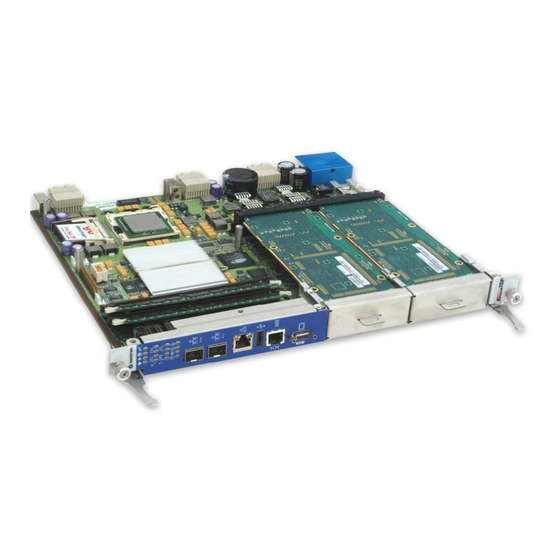
1.1 Product Overview The Kontron AT8001 ATCA PICMG 3.0/3.1 processor board is simply the most unique AdvancedTCA platform on the market. When first launched, it was the only AdvancedTCA blade to feature a low ® ® voltage, high performance Intel Xeon processor which scales up to 2.8 GHz, plus support two... -
Page 20: What's Included
1.2 What’s Included This board is shipped with the following items: 1. One Quick Reference Sheet. 2. One CD-ROM containing drivers. 3. One AT8001 board 4. Cables that have been ordered If any item is missing or damaged, contact the supplier. 1.3 Board Specifications FEATURES DESCRIPTION... - Page 21 Board Specifications (continued) Description Front Plate Rear I/O Total Video Serial PS/2 Mouse PS/2 Keyboard Ethernet Management Ethernet Base 2 (backplane) Ethernet Fabric 2* (backplane) Reset Button Fibre Channel (Optional) Description Onboard Rear I/O Mezzanine Total Hard Disk (SATA) Hard Disk (PATA) 1(PMC option) Compact Flash * Various combinations through cross point switches...
- Page 22 Board Specifications (continued) • AMI BIOS • Save CMOS in Flash option • Boot from gigabit Ethernet (Base and Fabric) • Boot from USB 2.0 (floppy, CD-Rom, hard disk) • Auto configuration, extended setup and VGA disable by jumper • Diskless, keyboard less, and video less operation extensions •...
- Page 23 Board Specifications (continued) Operating Storage and Transit Temperature* 0-55°C/32-131°F -40 to +70°C/-40 to 158°F Air Flow* Consult table below Humidity* 15% to 90% @55°C/131°F 5% to 95% @ 40°C/104°F non-condensing non-condensing Environmental Altitude* 4,000 m / 13,123 ft 15,000 m / 49,212 ft Shock* 30G, half-sine 11ms, each axis Bellcore GR-63-CORE...
-
Page 24: Compliance
1.4 Compliance This product conforms to the following specifications: • PICMG3.0R1.0 (Advanced TCA core specification) • PICMG3.1R1.0 (Ethernet/Fiber Channel over Advanced TCA) • AMC.0 R1.0 (Advanced mezzaninne card base specification) • AMC.1 R1.0 (Advance mezzaninne card PCI-Express) • IEEE STD 1386.1-2001 (PMC) •... -
Page 25: Interfacing With The Environment
Some I/O can be accessed through the use of a RTM. RTM use a proprietary pinout in J30 (Zone 3 connector) to bring out some I/O of the SBC. Only use Kontron’s RTM with the AT8001. Currently compatible RTM is the RT8000. - Page 26 Gigabit Ethernet on port 0 and 1 are connected to T5002 cross point switches. This allow to route these signals to the front SFP modules, onboard LAN, to the backplane or between the two AMC. Moreover, it is possible to use different signaling than gigabit ethernet 1000Base-BX since cross point switches are not aware of data encoding.
-
Page 27: Onboard Features
2. Onboard Features Contents Block Diagram..........2-10 System Core ..........2-12 6300ESB ICH..........2-15 W83627HF Super I/O ........2-19 i6700PXH Bridge .......... 2-19 LSIFC929X Fibre Channel (optional) ....2-20 Ethernet Interfaces........2-21 Crosspoint Switches ........2-22 Video Interface ..........2-23 2.10 AMC Mezzanines(optional) ...... -
Page 28: Block Diagram
2.1 Block Diagram 2-10 AT8001 User’s Guide... - Page 29 Some notes regarding the block diagram. • Front/Rear connection for the video is selected with a jumper • Front/Rear connection for 100Base-T LAN is selected in the BIOS setup • Manufacturing option: PATA hard-disk and PMC Mezzanine or AMC-B1 and AMC-B2 •...
-
Page 30: System Core
2.2 System Core 2.2.1 Processors The Intel® Xeon™ processor with 800 MHz system bus is designed for high-performance. Based on the Intel® NetBurst™ microarchitecture and the Hyper-Threading Technology, it is binary compatible with previous Intel Architecture (IA-32) processors. The Intel Xeon processor with 800 MHz system bus delivers compute power at unparalleled value and flexibility for powerful workstations, internet infrastructure, and departmental server applications. - Page 31 Please call Kontron to get the available CPU speed and configuration. See Intel’s Web site for additional details about Intel® Xeon™ architecture and instruction set. 2.2.2 E7520 MCH Supports Intel® Xeon™ Processors with 800 MHz system bus 800 MHz system bus(2X address, 4X data)
- Page 32 Support for automatic read retry on uncorrectable errors Support for memory mirroring Hardware periodic memory scrubbing, including demand scrub support Support for Intel® x4 Single Device Data Correction (x4 SDDC) Support for standard SEC-DED (72, 64) ECC on each channel when x4 SDDC technology is disabled Note: Many errors can be monitored by setting the DMI event BIOS menu such as ECC errors, parity...
-
Page 33: 6300Esb Ich
2.3 6300ESB ICH 2.3.1 Enhanced IDE Interfaces EIDE interface is part of 6300ESB south bridge. The interface conforms to the ATA specification and support ATA100 for 100MB/s burst transfer. The board features two interfaces and it supports only one 2,5” hard disk in Master configuration. Signal Signal OPT_A... - Page 34 The IDE interfaces supports PIO mode 4 transfers up to 16.6MB/sec and Bus Master IDE transfer up to 100MB/sec (Ultra-DMA/100). 2.3.2 CompactFlash Interfaces (J21) The board features a CompactFlash connector. Any Type 1 CompactFlash can be used. It is connected to the Primary IDE logical interfaces and is set in master mode.
- Page 35 Bios Settings: - Main - Specify disk type - Advanced IDE Configuration 2.3.4 USB 2.0 Interfaces USB strengths include: Capability to daisy chain as many as 127 devices per interface Fast bi-directional Isochronous/asynchronous interface 480 MBPS transfer rate Standardization of peripheral interfaces into a single format Retro compatible with USB 1.1 devices USB supports Plug and Play and hot-swapping operations (OS level).
- Page 36 Optionally a RJ-45 10 pins connector may be populated which allow to use RI and DCD. Contact Kontron’s technical support if you are interested with this option. The pinout is a custum one, not the same as RS-232D EIA-561. Use the Kontron provided RJ45 to DB9 adapter.
-
Page 37: W83627Hf Super I/O
Although it is possible to save the CMOS setup in NVRAM (or CMOS RAM), the default configuration saves the setup in flash. So, when the AT8001 in unpowered for too long, only the time will be lost. 2.4 W83627HF Super I/O 2.4.1 PS/2 Keyboard / PS/2 Mouse Interfaces This board supports PS/2 keyboard and mouse through a RTM only. -
Page 38: Lsifc929X Fibre Channel (Optional)
2.6 LSIFC929X Fibre Channel (optional) The two fibre channel interfaces are based on the dual port LSIFC929X controller. Those can be use for storage and networking. Interfaces support for 2Gb/s and 1Gb/s signalling. See Kontron’s Web site: http://www.kontron.com for the latest drivers. -
Page 39: Ethernet Interfaces
The AT8001 has a 100Base-T LAN based on the 82551ER that can be accessed on the front plate or the RTM (if available). Use the BIOS setup to specify where the LAN will be used. Note that this LAN has no boot from LAN support. See Kontron’s Web site: http://www.kontron.com for the latest drivers. -
Page 40: Crosspoint Switches
Signal Paths: The Ethernet Management RJ45 connector is on the faceplate. BIOS Settings: Advanced On-Board Devices Configuration On-board Dual Ethernet 1 2.7.3 i82546GB Fabric/Front Interface A second i82546GB is used in various configurations. The 2 ethernet ports are routed to the cross point switches allowing many configurations. -
Page 41: Video Interface
If using two AMC with 6.5Gb/s signalling on AMC port 0, it is possible to connected those together since the VSC3108 are protocol-agnostic. Common configurations have been included in the BIOS setup. For unsupported configurations, consult Kontron Canada technical support. Bios Settings: Advanced ATCA Channel Routing (PICMG). -
Page 42: Amc Mezzanines(Optional)
Signal Paths: Video signals are available through J6 (Front panel connector) or from Rear I/O connector If you use the front video connector you will need to use the appropriate adapter cable. Related Jumpers: JP4 enables or disables the onboard video. JP5 is used to set the video position in front or rear. -
Page 43: Pmc Mezzanine(Optional)
As per AMC.1 R1.0, the carrier board (At8001) is required to provide PCI-E 100MHz reference clock to the AMC on CLK3. However, modules are not required to use it. Kontron recommend using AMC- Express modules that use the reference clock on CLK3. If the module makes its own reference clock, then the spread spectrum of the AT8001 clock synthesizer needs to be disabled in the BIOS setup, otherwise the behavior of the PCI-Express link will be erratic at best. -
Page 44: Fpga
The FWUM itself is a microcontroller with internal flash to store IPMC firmware image. This microcontroller is also an external watchdog for the IPMC. Functions of this microntroller is kept to a minimum. The FWUM firmware is field updatable. Note: The IPMC and the FWUM have an internal hardware watchdog. -
Page 45: Hardware Management Overview
This circuit is available on AT8001 with AMC support only.The PLD is field upgradable. Customization on this device for additionnal feature is possible. Contact Kontron’s technical support for this service. If upgrade are necessary for this device, an appropriate procedure will be provided with the code update. - Page 46 The IPMC provides six I2C bus connections. Two are used as the redundant IPMB bus connections to the backplane, one is used for IPMB-L bus with AMC modules, two others I2C are used to LAN connections for IPMI over LAN support and the last one is for local EEPROM storage. If an IPMB bus fault or IPMC failure occurs, IPMB isolators are used to switch and isolate the backplane/system IPMB bus from the faulted SBC board.
- Page 47 2.16.2 Hardware Sensors Sensor Name Voltage/Signals Monitored Scanning Enabled under Power State Health LED (Green to Red) Vcc 1.5v FRU0 +1.5 V Power On Exceeds critical threshold +2.5 V Power On Exceeds critical threshold Vcc 2.5v FRU0 +1.8 V Power On Exceeds critical threshold Vcc 1.8v FRU0 VTT DDR (+1.25 V)
- Page 48 CPU Critical PCI SERR Power On No change Interrupt PCI PERR Power On No change System Firmware Power On No change Progress Memory Error ECC Multiple Bit error Power On No change ECC Single Bit error Power On No change IPMI Watchdog IPMC Watchdog Timer timeout Power On/Off...
- Page 49 IPMC Firmware Upgrade Procedure It is important to use compatible BIOS, IPMC, FWUM and FPGA versions. Since all these software and hardware solution are exchanging information, they must be in synch. Please always follow Kontron documentation for all your upgrade.
- Page 50 Menu. The BIOS Setup does also provide the IPMC firmware version, via the IPMI Menu. FWUM Firmware upgrade is done using IPMIFWU utility. This is a Linux utility developed by Kontron that use the serial port to exchange with the FirmWare Upgrade Manager (FWUM) in order to upgrade to FWUM or the IPMC firmware.
- Page 51 2.16.9 OEM IPMI Commands This section documents the OEM style IPMI commands implemented and supported on the AT8001. Command Name NetFunction Command Reset BIOS Flash Type Get Fibre Channel Port Selection Set Fibre Channel Port Selection Get HW Fibre Channel Port Selection Set Control State Get Control State 2.16.9.1...
- Page 52 2.16.9.4 Controls Identifier Table This table lists the control identifiers that can be used with Set/Get Control State IPMI commands to query or set information on certain controls in the firmware. Control Description Control Number FWH Hub (for BIOS bank information)0 FWH 0 Write Protect FWH 1 Write Protect FWH 0 Top Block Lock...
- Page 53 to move to the M6 state. The Hot Swap LED will indicate this state with a short blink. Once permission is received from the SHMC or higher-level software, the SBC will move to the M6 state. The SHMC or higher level software can reject the request to move to the M6 state. If this occurs, the Hot Swap LED returns to a solid off condition, indicating that the SBC has returned to M4 state.
-
Page 54: Debugging Features
2.17 Debugging Features 2.17.1 POST Code Blinker / IDE Activity The postcode blinker circuit uses a blinking sequence to display the current POST (Power On Self Test) code value on faceplate. This functionality is shared with the hard drive activity LED. This sequence restarts every time the POST codes value changes. - Page 55 2.17.2 Serial POST Codes Kontron's serial POST Code display module (T2603) can be used with this board. The module is plugged on J13 or on the RTM RT8000 if available. It can display the BIOS POST codes (i.e. content of I/O locations 80-81h) or the IPMC POST codes depending on the presence of jumper JP7(1-2).
- Page 56 2.17.4 Lamp Test The lamp test does the sequence shown below in the order 1-2-3-4-1-2-3- etc. Step 4 is not displayed when the regional bit is set for Europe (no red allowed). The lamp test can be initiated by software (IPMC) or just by pressing the reset pushbutton long enough. LED arangement and face plate finish may vary depending on board configuration.
-
Page 57: Installing The Board
3. Installing the board Contents Setting Jumpers ..........3-1 Processor ............3-3 Memory ............3-3 Onboard Interconnectivity ....... 3-5 Board Hot Swap and Installation....... 3-7 AT8001 User’s Guide... -
Page 58: Setting Jumpers
3.1 Setting Jumpers 3.1.1 Jumper Description Description Clear CMOS To clear the CMOS, power down the board, put the jumper in for a second and then remove it. Console Redirection To enable the Console Redirection Mode, put the jumper in. Onboard Video Use this jumper to disable the onboard video feature. - Page 59 3.1.2 Setting Jumper & locations AT8001 User’s Guide...
-
Page 60: Processor
This product ships with the CPU installed and a thermal solution installed. Because the thermal solution is custom and the thermal interface is critical for passive cooling, Kontron does not guarantee thermal performance if the heat sink is removed and then reinstalled by the end user. - Page 61 3.3.1 Installing Memory On an anti-static plane, place the board so that you are facing the memory sockets Insert the memory module into any available socket, aligning the notches on the module with the socket’s key inserts. Push down the memory module until the retaining clips clip on each side.
-
Page 62: Onboard Interconnectivity
J10,J12 2.5” Hard Disk 50 pins connector for use with IDE platform (Optional) POST Code Connector Four pin connector for use with Kontron T2601 postcode module. Standard type B+ AMC connector (Optional) AMC B1 AMC B2 Standard type B+ AMC connector(Optional) - Page 63 Use an appropriate module depending on the data that will be SFP Channel A routed to the SFP from the cross point switch. Kontron provides 2Gb module that will work for Fibre channel and gigabit Ethernet SFP Channel B Same as above.
-
Page 64: Board Hot Swap And Installation
3.5 Board Hot Swap and Installation Because of the high-density pinout of the hard-metric connector, some precautions must be taken when connecting or disconnecting a board to/from a backplane: 1. Rail guides must be installed on the enclosure to slide the board to the backplane. 2. - Page 65 3.5.2 Removing the Board If you would like to remove a card from your chassis please follow carefully these steps: 1. Unscrew the top and the bottom screw of the front panel. 2. Unlock the lower handle latch, depending on the software step, this may initiate a clean shutdown off the operating system.
- Page 66 3.5.5 Installing an hard disk To install an hard disk: 1. Carefully connect the disk to the IDE connector. 2. Screw the four screws at the bottom of the board to fix it to the board. 3. Boot the AT8001 and make sure the drive is detected by the BIOS setup. WARNING - This feature is only available when you don’t a have a AMC - You cannot have an hard disk and a AMC at the same time...
-
Page 67: Building An Atca System
4. Building an ATCA System Contents Building an ATCA System ......... 4-1 AT8001 User’s Guide... -
Page 68: Building An Atca System
For more information about the RT8000 transition module, please consult our web site at: www.kontron.com WARNING Always use Kontron’s RTM with your Kontron’s front board or permanent damage could occur. AT8001 User’s Guide... - Page 69 Mechanical keying in ATCA system exists for the main backplane and for RTM. Currently only one key is defined for ATCA front board: A1/K1 key value is 11. RTM key is defined by front board manufacturer. Currently, Kontron use the A2/K2 value of 11 for it’s front CPU board and matching RTM.
-
Page 70: Software Setup
5. Software Setup Contents AMI BIOS Setup Program........5-1 Boot Utilities ..........5-24 Console Redirection (VT100 Mode)....5-25 Installing Drivers ......... 5-28 MontaVista ..........5-29 AT8001 User’s Guide... -
Page 71: Ami Bios Setup Program
When you get the following messages, hit <DELETE> key (or F4 on Remote Keyboard) to enter SETUP. AMIBIOS(C)2003 American Megatrends, Inc. KONTRON AT8001 BIOS Version 0.18 CPU : Intel(R) Xeon(TM) CPU 2.80GHz Speed : 2.80 GHz Press DEL to run Setup (F4 on Remote Keyboard) Press F11 for BBS POPUP (F3 on Remote Keyboard) (C) American Megatrends, Inc. - Page 72 The main menu of the AMI BIOS CMOS Setup Utility appears on the screen. KONTRON AT8001 BIOS Version 0.18 Main Advanced PCIPnP Boot Security Chipset Exit System Overview Use [ENTER], [TAB] --------------------------------------------------- or [SHIFT-TAB] to AMIBIOS select a field. Version :08.00.11...
- Page 73 5.1.2 Menu Bar The Menu Bar at the top of the window lists these selections: Menu Selection Description Main Use this menu for basic system configuration. Advanced Use this menu to set the Advanced Features available on your system. PCIPnP Use this menu to configure PCI and PnP features.
- Page 74 5.1.2.2 Field Help Window The help window on the right side of each menu displays the help text for the selected field. It updates as you move the cursor to each field. 5.1.2.3 General Help Windows Pressing <F1>on any menu brings up the General Help window that describes the legend keys and their alternates: General Help ←→...
- Page 75 5.1.2.4 Main Menu Selection The scroll bar on the right of any windows indicates that there is more than one page of information in the windows. You can make the following selections on the Main Menu itself. Use submenus for other selections.
- Page 76 5.1.2.5.1 CPU Configuration Feature Options Description Manufacturer Brand String Frequency Configure FSB Speed advanced CPU Cache L1 Displays only. settings Cache L2 Cache L3 Ratio Status Ration Actual Value Varies. Values Ratio CMOS available are based on Will display if CPU ratio is locked or unlocked and the Setting minimum/maximum minimum/maximum ratios available.
- Page 77 5.1.2.5.2 IDE Configuration Feature Options Description Select IDE Mode. P-ATA Only: Disabled 4 P-ATA & 2 S-ATA P-ATA Only Configuration S-ATA Only S-ATA Only: P-ATA & S-ATA 2 S-ATA P-ATA & S-ATA: 2 P-ATA & 2 S-ATA S-ATA Running Set S-ATA Running Enhanced Mode. Enhanced Mode Primary P-ATA Channel...
- Page 78 5.1.2.5.2.1 Primary IDE Master Feature Options Description Device Vendor Size LBA Mode Primary IDE This is a list of modes and features supported by the drive, not Block Mode Master how it is setup. PIO Mode Async DMA Ultra DMA S.M.A.R.T.
- Page 79 5.1.2.5.2.2 Primary IDE Slave Feature Options Description Device Vendor Size LBA Mode Primary IDE This is a list of modes and features supported by the drive, not Block Mode Slave how it is setup. PIO Mode Async DMA Ultra DMA S.M.A.R.T.
- Page 80 5.1.2.5.2.3 Secondary IDE Master Feature Options Description Device Vendor Size LBA Mode Secondary IDE This is a list of modes and features supported by the drive, not Block Mode Master how it is setup. PIO Mode Async DMA Ultra DMA S.M.A.R.T.
- Page 81 5.1.2.5.2.4 Secondary IDE Slave Feature Options Description Device Vendor Size LBA Mode Secondary IDE This is a list of modes and features supported by the drive, not Block Mode Slave how it is setup. PIO Mode Async DMA Ultra DMA S.M.A.R.T.
- Page 82 5.1.2.5.2.5 Third IDE Master Feature Options Description Device Vendor Size LBA Mode This is a list of modes and features supported by the drive, not Third IDE Master Block Mode how it is setup. PIO Mode Async DMA Ultra DMA S.M.A.R.T.
- Page 83 5.1.2.5.2.6 Fourth IDE Master Feature Options Description Device Vendor Size LBA Mode Fourth IDE This is a list of modes and features supported by the drive, not Block Mode Master how it is setup. PIO Mode Async DMA Ultra DMA S.M.A.R.T.
- Page 84 5.1.2.5.3 SuperIO Configuration Feature Options Description Disabled 3F8/IRQ4 ICH SIO Serial Allows BIOS to select ICH Serial I/O Unit Serial Port 1 Base 2F8/IRQ3 Port1 Address Addresses 3E8/IRQ4 2E8/IRQ3 Disabled 3F8/IRQ4 ICH SIO Serial Allows BIOS to select ICH Serial I/O Unit Serial Port 2 Base 2F8/IRQ3 Port2 Address Addresses...
- Page 85 5.1.2.5.4.2 Chipset ACPI Configuration Feature Options Description APIC ACPI SCI Disabled Enable/Disable APIC ACPI SCI IRQ. Enabled 5.1.2.5.5 Event Log Configuration Feature Options Description View Event Log View all unread events Mark all events Mark all unread events as read. as read Clear Event Log Discard all events in the Event Log.
- Page 86 5.1.2.5.7 ATCA Channel Routing (PICMG) Feature Options Description Actual Fabric LAN A Port Display Only Display hardware actual state. State Select the front panel or backplane (ATCA) Channel connection. Disabled Fabric LAN A Warning! To switch the ports to backplane, you need E-key Front Panel A Port Setting granting from ShMC.
- Page 87 5.1.2.5.8 On-Board Devices Configuration Feature Options Description On-board Fiber This is a title. Configure On-board Fibre Channel Controller Channel Disabled Option ROM Initialize device expansion ROM. Enabled On-Board Dual This is a title. Configure On-board Dual-Ethernet 1 Controller Ethernet 1 Option ROM Disabled Initialize device expansion ROM.
- Page 88 5.1.2.5.10 Remote Access Configuration Feature Options Description Console Display the hardware state of the Remote access jumper. The Redirection Display only. jumper can overwrite the CMOS setting to enable the console Jumper redirection. Disabled Remote Access Select Remote Access Type Enabled Select Serial Port for console redirection Serial Port...
- Page 89 5.1.2.5.11 IPMI Configuration Feature Options Description Indicate the status of IPMI SMM KCS interface, this is not a self- Status of IPMC Display only test results. IPMI Device and Firmware This is a Sub-Menu View IPMI Device and Firmware Information Information FRU Board This is a Sub-Menu...
- Page 90 5.1.2.5.12 USB Configuration Feature Options Description Disabled USB Function 2 USB Ports Enables USB Host controllers. All USB Ports Disabled Legacy USB Enables Support for legacy USB. Auto option disables legacy Enabled Support support if no USB device are connected Auto USB 2.0 Enabled...
- Page 91 5.1.2.7 Boot menu Feature Options Description Boot Setting This is a sub-menu Configure Settings during System Boot. Configuration Boot Device This is a sub-menu Specifies the Boot Device Priority sequence. Priority Specifies the Boot Device Priority sequence from available Hard Disk Drives This is a sub-menu Hard Drives.
- Page 92 5.1.2.7.3 Hard Disk Drives Feature Options Description Drive Varies Specifies the boot sequence from the available devices. Drive Varies Number of entries will vary based on system configuration. Note: The easiest way to select the desired priority is to select the 1 Drive, Hit Enter and choose a device from the options presented.
- Page 93 5.1.2.10 Exit Feature Options Description Save Changes and Exit system dsetup after saving the changes. Exit F10 key can be used for this operation. Discard Changes Exit system setup without saving any changes. and Exit ESC key can be used for this operation. Discard Changes done so far to nay of the setup questions.
-
Page 94: Boot Utilities
5.2 Boot Utilities AMI Boot Utilities are: Boot Menu POP-UP Boot Menu POP-UP is a boot screen that displays a selection of boot devices from which you can boot your operating system. 5.2.1 Pressing <Del> (or <F4> from a Console Redirection terminal) Pressing <... -
Page 95: Console Redirection (Vt100 Mode)
5.3 Console Redirection (VT100 Mode) The VT100 operating mode allows remote setup of the board. This configuration requires a remote terminal that must be connected to the board through a serial communication link. 5.3.1 Requirements The terminal should emulate a VT100 or an ANSI terminal. Terminal emulation programs such as ©... - Page 96 Console Redirection provided by AMI based BIOS can reset the target system using the sequence “Ctrl Shift –“. 5.3.3 Running Without a Terminal The board can boot up without a screen or terminal attached. If the speed is set to Auto and no terminal is connected, the speed is set to 115,200 bauds.
- Page 97 The following “escape sequences” are defined in the “Conventions for Keys Not in VT100 Terminal Definition and ASCII Character Set” section of “Standardizing Out-of-Band Management Console Output and Terminal Emulation (VT-UTF8 and VT100+)”,available for download at microsoft.com. F1 Key <ESC>1 F7 Key <ESC>7 Alt Modifier<ESC>^A...
- Page 98 5.4.4 Other Drivers For other operating system drivers and installation instructions or for more information, visit our Web site at www.kontron.com or our FTP site at ftp.kontron.ca/support/ or you may also contact Kontron’s Technical Support department. 5-28 AT8001 User’s Guide...
- Page 99 Manual Extract the LSP archive to a new directory: gzip –dc {filename} | tar –xvf - Install the LSP: mvl-rpm –ihv PATH_TO_LSP/cross-x86_pentium4-lsp-kotron_t5002-2.4.20_mvlcge31-041203.noarch.mvl Install the Kontron Support Toolkit package: mvl-rpm --target=x86_pentium4-linux –ihv PATH_TO_LSP/kst-0.1-041203.x86_pentium4.mvl 5.5.3 Configuration Create a project using the LSP: Open the Target Configuration Tool and click on the New Project button.
- Page 100 “kontron_toolkit” available in the package list. Note: The Kontron support toolkit package is subdivided in three categories. The base category (needed for the complete shutdown script), The IPMI category (needed for IPMI firmware update and IPMI accessibility) and BIOS (needed for updating the bios flash device).
- Page 101 Appendix Contents A - Memory & I/O Maps ..........A-1 B - Kontron Extension Registers ........B-1 C – Connector Pinouts ..........C-1 D – BIOS Setup Error Codes..........D-1 E – Software Update............. E-1 F – Getting Help ............F-1 AT8001 User’s Guide...
-
Page 102: A - Memory & I/O Maps
Memory & I/O Maps MEMORY MAPPING Address Function 00000-9B7FF 0-622 KB DRAM 9B800-9FFFF 622KB – 640 KB XBDA; USB Legacy / BIOS Stack A0000-BFFFF Video DRAM C0000-CBFFF Video BIOS Optional ROM (Free) CC000-DBFFF LAN BIOS around 30KB if activated, address may vary External Fiber Channel BIOS 18KB-64KB , address may vary E0000-FFFFF System BIOS... - Page 103 3F0-3F7 Floppy Disk 3F8-3FF (COM1) 2F8-2FF (COM2) Serial Port 1 (COM1 by default) 2F8-2FF (COM2) 3F8-3FF (COM1) Serial Port 2 (COM2 by default) 400-9FF Chipset Reserved A00-A1F Kontron Registers (on-board) A20-A2F Kontron Registers (RTM) B00-0FFF Chipset Reserved AT8001 User’s Guide...
- Page 104 PCI IDSEL and Device numbers Funct. V. ID D. ID Description PCI Description SEL# E7520 – Memory Controller Bridge, host-bridge, multi- 8086h 3590h function E7520 – Memory Error Bridge, host-bridge, multi- 8086h 3591h Reporting function System peripheral, non- 8086h 3594h E7520 –...
- Page 105 i6700PXH – PCI-Express to 8086h 0329h PCI Bridge (P2P-A) 8086h 0326h i6700PXH – I/OxAPIC-A i6700PXH – PCI-Express to 8086h 032Ah PCI Bridge (P2P-B) 8086h 0327h i6700PXH – I/OxAPIC-B AD17 8086h 1079h I82546GB AD17 8086h 1079h I82546GB AD18 8086h 1079h I82546GB AD18 8086h 1079h...
-
Page 106: B - Kontron Extension Registers
Kontron Extension Registers FPGA/CPLD REGISTERS DEFINITION Unused bits are reserved. To insure compatibility with other product and upgrades to this product, do not modify unused bits. Bits marked NU are not used on this board. Writing to such bit does nothing and reading is undefined, either 0 or 1 may be returned. - Page 107 0080H: POSTCODES Address Action READ Postcode 0x080 WRITE Postcode Reset Postcode Postcodes are captured in this register as they are written. 0081H: EXTENDED POSTCODES Address Action READ Postcode 0x081 WRITE Postcode Reset Postcodes are captured in this register as they are written. Be carefull that postcodes are not Postcode always 16-bit and the high byte in register 81h could be unrelated to the content of register 80h.
- Page 108 About the debug LED: The idea is that the LED will light amber/green when in reset (this is hardware). As soon as the FPGA is programmed, the LED lights amber and is enabled for post-code display (see bellow). If the BIOS fail, it is possible to read the post-code. If the BIOS succeed, it will disable the post-code and enable HD activity on the green LED.
- Page 109 0A04H: DEVELOPMENT FEATURES Address Action READ MinorVersion SSC1 SSC0 0xA04 WRITE SSC1 SSC0 Reset MinorVersion MinorVersion Minor version that doesn't impact the IPMC. For in-house minor version tracking. SSC0 Special Serial Connection bit 0 SSC1 Special Serial Connection bit 1 PCB Version.
- Page 110 0A08H: TELCLOCK0 (TELECOM CLOCK OPTION) Address Action HWMODE HO_LOS REFALIGN E3DS3 E3DS3OC3 READ HWMODE HO_LOS REFALIGN E3DS3 E3DS3OC3 0xA08 WRITE Reset HWMODE Enable automatic switching by hardware. HO_LOS Switch criteria in HW mode. When set, use PLL holdover detection as the switch criteria. When cleared, use loss of clock (internal to PLD) as the switch criteria.
- Page 111 REFSEL Show the reference that is currently selected. 0: Primary reference 1: Secondary reference RSV1/ RSV0 Reserved. B.11 0A0AH: TELCLOCK2 (TELECOM CLOCK OPTION) Address Action PRI_LOS SEC_LOS HOLDOVER UNLOCK DRVCLKA1 DRVCLKA0 READ DRVCLKA1 DRVCLKA0 0xA0A WRITE Reset PRI_LOS Loss of primary reference clock detected. This bit is high when the primary clock at the input of the PLL (i.e.
- Page 112 B.12 0A0BH: TELCLOCK3 (TELECOM CLOCK OPTION) Address Action DRVCLK3B DRVCLK3A TXREF1_SEL[2..0] TXREF0_SEL[2..0] READ DRVCLK3B DRVCLK3A TXREF1_SEL[2..0] TXREF0_SEL[2..0] 0xA0B WRITE Reset DRVCLK3B Enable MLVDS buffer to drive CLK3B to the backplane This bit is forced to 0 until the IPMC authorizes it. DRVCLK3A Enable MLVDS buffer to drive CLK3A to the backplane This bit is forced to 0 until the IPMC authorizes it.
- Page 113 B.13 0A0CH: TELCLOCK4 (TELECOM CLOCK OPTION) Address Action READ IRQTST RESET TEST 0xA0C WRITE IRQTST RESET TEST Reset IRQTST Interrupt test. The state of this bit is ored with the real interrupt. This bit is for software testing. Ignore in normal operation. A "1" assert the interrupt request. TEST Ignore IPMC &...
- Page 114 B.15 0A0EH: TELCLOCK6 (TELECOM CLOCK OPTION) Address Action UNLOCK10 UNLOCK01 HLDOVR10 HLDOVR01 SEC10 SEC01 PRI10 PRI01 READ 0xA0E WRITE Reset PRI01 Bit PRI_LOS in register TelClock2 switched from 0 to 1. PRI10 Bit PRI_LOS in register TelClock2 switched from 1 to 0. SEC01 Bit SEC_LOS in register TelClock2 switched from 0 to 1.
-
Page 115: C - Connector Pinouts
Connector Pinouts CONNECTORS AND HEADERS SUMMARY Connector Description Fiber Channel 0 / RJ45 Connector Fiber Channel 1 / RJ45 Connector Ethernet Management USB 0 Serial Port (RJ-45) 2.5” Hard Disk connector POST Code Connector CompactFlash ATCA Base & Fabric Interface ATCA RTM Connector ATCA Power PMC Connector... - Page 116 FIBER CHANNEL (J1 & J2) Signal Signal VEET_1 VEER_3 TX_FAULT TX_DIS MODDEF2 VEER_4 MODDEF1 VCCR MODEFF0 VCCT R_SEL VEET_2 VEER1 VEER2 VEET_3 cGND_1 cGND_2 cGND_3 cGND_4 cGND_5 cGND_6 cGND_7 cGND_8 cGND_9 cGND_10 cGND_11 ETHERNET MANAGEMENT (J3) Signal Yellow Note N.C. These two LEDs N.C.
- Page 117 SERIAL PORT 1 - RS-232 (J5) Signal Signal VIDEO (SVGA) (J6) Signal Signal N.C. GREEN BLUE N.C. N.C. SDATA HSYNC VSYNC SCLCK AT8001 User’s Guide...
- Page 118 2.5” IDE HARD DISK (J11) Signal Signal OPT_A OPT_B OPT_C OPT_D N.C. N.C. RESET# DD10 DD11 DD12 DD13 DD14 DD15 DMARQ DIOW# DIOR# IORDY CSEL# DMASK# INTRQ PDIAG# CS0# CS1# DASP# # Active Low Signal POST CODE (J13) Signal VCC3 DATA CLOCK AT8001 User’s Guide...
- Page 119 AMC B1 & AMC B2 (J18 & J19) Signal Signal Signal Signal B129 TxD15-(N.C.) RxD4+ TxD8- B130 TxD15+(N.C.) PS1# RxD4- TxD8+ B131 MP_3V3 B132 RxD15-(N.C.) TxD4+ RxD8- B133 RxD15+(N.C.) TxD4- RxD8+ B134 B135 TxD16-(N.C.) RxD5+ TxD9- B136 TxD16+(N.C.) RxD5- TxD9+ B137 B138 RxD16-(N.C.)
- Page 120 C.10 COMPACTFLASH™ (J21) Signal Signal CS0# VCC3 N.C. N.C. N.C. DD11 DD12 DD13 DD14 DD15 CS1# N.C. DIOR# DIOW# WE#(3.3V) INTRq VCC3 CSEL#(GND) N.C. RESET# IORDY DMARQ DMACK# DASP# PDIAG# DD10 # Active Low Signal AT8001 User’s Guide...
- Page 121 C.11 TELCO CLOCK (J20) ROW A ROW B ROW C ROW D ROW E ROW F CLK1A+ CLK1A CLK1B+ CLK1B CLK2A+ CLK2A Tx4(UP)+(N.C.) Tx4(UP) -(N.C.) Rx4(UP)+(N.C.) Rx4(UP) - (N.C.) CLK3A+ CLK3A Tx2(UP)+(N.C.) Tx2(UP) - (N.C.) Rx2(UP)+(N.C.) Rx2(UP) - (N.C.) Tx3(UP)+(N.C.) Tx3(UP) - (N.C.) Tx0(UP)+(N.C.) Tx0(UP) - (N.C.)
- Page 122 C.12 ATCA I/O (J23) ATCA 3.1 ROW A ROW B ROW C ROW D ROW E ROW F Tx2[2]+(N.C.) Tx2[2]-(N.C.) Rx2[2]+(N.U.) Rx2[2]-(N.U.) Tx3[2]- Tx3[2]- Tx0[2]+ Tx0[2]- Rx0[2]+ Rx0[2]- Tx1[2]+ Tx1[2]- Tx2[1]+(N.C.) Tx2[1]-(N.C.) Rx2[1]+(N.U.) Rx2[1]-(N.U.) Tx3[1]+ Tx3[1]- Tx0[1]+ Tx0[1]- Rx0[1]+ Rx0[1]- Tx1[1]+ Tx1[1]- BI_DA1+...
- Page 123 C.13 RTM Connector (J30) ROW A ROW B ROW C ROW D ROW E ROW F USB1_VCC(N.C.) USB0_VCC PS2_CLK PS2_DAT LAN_DA- LAN_DA+ BRD_RESET# TEST_SPKR# KBD_CLK KBD_DAT LAN_DB- LAN_DB+ 3.3V_SUS SMB_SCL SMB_SDA LAN_DC- (N.C.) LAN_DC+ (N.C.) JTAG_CFG(N.C.) TEST_ON# POST_CLK POST_DAT LAN_DD- (N.C.) LAN_DC- (N.C.) JTAG_TDO TEST_JIG#...
- Page 124 C.14 POWER (P10) Signal Signal N.P. N.P. N.P. N.P. HA7/P IPMBA_SCL SDA_A SCL_B SDA_B N.C. N.C. N.C. N.C. N.C. N.C. N.C. N.C. SHELF_GND LOGIC_GND ENABLE_B VRTN_A VRTN_B EARLY_A EARLY_B ENABLE_A -48V_A -48V_B # Active Low Signal C-10 AT8001 User’s Guide...
- Page 125 C.15 JN1 – PMC (JN1) Signal Signal TCK(N.C.) -12V INTA# INTB# INTC# BUSMODE1# INTD# PCI-RSV 3V3_AUX (N.C.) GNT# REQ# AD31 AD28 AD27 AD25 C/BE#3 AD22 AD21 AD19 AD17 FRAME# IRDY# DEVSEL# PCIXCAP LOCK# PCI-RSV PCI-RSV AD15 AD12 AD11 C/CBE0# REQ64# # Active Low Signal C-11 AT8001 User’s Guide...
- Page 126 C.16 JN2 – PMC (JN2) Signal Signal +12V TRST#(GND) TMS(N.U.) TDO(N.U.) TDI(N.U.) PCI-RSV PCI-RSV PCI-RSV BUSMODE2# RST# BUSMODE3# BUSMODE4# PME#(N.U.) AD30 AD29 AD26 AD24 IDSEL AD23 AD20 AD18 AD16 C/BE2# PMC-RSV TRDY# STOP# PERR# SERR# C/BE1# AD14 AD13 M66EN AD10 PMC-RSV PMC-RSV PMC-RSV...
- Page 127 C.17 JN3 – PMC (JN3) Signal Signal PMC-RSV C/BE7# C/BE6# C/BE5# C/BE4# PAR64 AD63 AD62 AD61 AD60 AD59 AD58 AD57 AD56 AD55 AD54 AD53 AD52 AD51 AD50 AD49 AD48 AD47 AD46 AD45 AD44 AD43 AD42 AD41 AD40 AD39 AD38 AD37 AD36 AD35 AD34...
-
Page 128: D - Bios Setup Error Codes
BIOS Setup Error Codes Bootblock Initialization Code Checkpoints The Bootblock initialization code sets up the chipset, memory and other components before system memory is available. The following table describes the type of checkpoints that may occur during the bootblock initialization portion of the BIOS: Checkpoint Description Before D1... - Page 129 POST Code Checkpoints The POST code checkpoints are the largest set of checkpoints during the BIOS pre-boot process. The following table describes the type of checkpoints that may occur during the POST portion of the BIOS: Checkpoint Description Disable NMI, Parity, video for EGA, and DMA controllers. Initialize BIOS, POST, Runtime data area.
- Page 130 Initializes DMAC-1 & DMAC-2. Initialize RTC date/time. Test for total memory installed in the system. Also, Check for DEL or ESC keys to limit memory test. Display total memory in the system. Mid POST initialization of chipset registers. Detect different devices (Parallel ports, serial ports, and coprocessor in CPU, … etc.) successfully installed in the system and update the BDA, EBDA…etc.
- Page 131 DIM Code Checkpoints The Device Initialization Manager (DIM) gets control at various times during BIOS POST to initialize different system busses. The following table describes the main checkpoints where the DIM module is accessed: Checkpoint Description Initialize different buses and perform the following functions: Reset, Detect, and Disable (function 0);...
- Page 132 3 = EISA devices. 4 = ISA PnP devices. 5 = PCI devices. ACPI Runtime Checkpoints ACPI checkpoints are displayed when an ACPI capable operating system either enters or leaves a sleep state. The following table describes the type of checkpoints that may occur during ACPI sleep or wake events: Checkpoint Description...
- Page 133 Processor error Keyboard controller BAT test error. General exception error. Display memory error. ROM checksum error CMOS shutdown register read/write error Cache memory bad D.6.1 Troubleshooting BIOS Beep Codes Number of Beeps Troubleshooting Action 1, 2 or 3 Reseat the memory, or replace with known good modules. 4-7, 9-11 Fatal error indicating a serious problem with the system.
-
Page 134: E - Software Update
Getting Help At Kontron, we take great pride in our customers’ successes. We believe in providing full support at all stages of your product development. If at any time you encounter difficulties with your application or with any of our products, or if you... - Page 135 • E-mail 1. Send us an e-mail at: RMA@ca.kontron.com. In the e-mail, you must include your name, your company name, your address, your city, your postal/zip code, your phone number, and your e-mail. You must also include the serial number of the defective product and a description of the problem.
- Page 136 _________________________ P.O. # Serial Number Failure or Problem Description (if not under warranty) Kontron Canada, Inc., 616 Curé Boivin, Boisbriand, Québec, Canada, J7G 2A7 Fax this form to Kontron’s Technical Support department in Canada at (450) 437-0304 AT8001 User’s Guide...
Need help?
Do you have a question about the AdvancedTCA AT8001 and is the answer not in the manual?
Questions and answers