Table of Contents
Advertisement
Quick Links
Advertisement
Table of Contents

Related Manuals for Kontron AdvancedTCA AT8901M


Summary of Contents for Kontron AdvancedTCA AT8901M
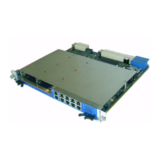
- Page 1 AT8901M USER GUIDE AdvancedTCA 3.5 Revision Index February 2009 Date of Issue...
-
Page 2: Imprint
Disclaimer Copyright © 2009 Kontron AG. All rights reserved. All data is for information purposes only and not guaranteed for legal purposes. Information has been carefully checked and is believed to be accurate; however, no responsibility is assumed for inaccuracies. Kontron and the Kontron logo and all other trademarks or registered trademarks are the property of their respective own- ers and are recognized. -
Page 3: Table Of Contents
AT8901M Preface Table of Content Revision History ......................ii Imprint ........................ii Disclaimer ........................ii Proprietary Note ......................ix Trademarks .......................ix Environmental Protection Statement .................ix Explanation of Symbols .....................x For Your Safety ......................x High Voltage Safety Instructions ................xi Special Handling and Unpacking Instructions ............xi General Instructions on Usage ................ - Page 4 AT8901M Preface Chapter Hardware Description .................. 3 - 2 3.1 CPU and Memory ..................3 - 3 3.2 Base Switch .................... 3 - 6 3.3 AMC Bays ....................3 - 9 3.4 IPMI ....................... 3 - 11 3.5 Synchronization Clock ................3 - 12 3.6 RTM Interface ..................
- Page 5 AT8901M Preface 4.2.4 QoS Package MIB ................4 - 7 4.3 Bootloader ....................4 - 7 4.3.1 Power On Self Test ................. 4 - 8 4.4 IPMI Firmware ..................4 - 10 4.4.1 Sensor Data Record (SDR) ............4 - 11 4.4.2 Field Replaceable Unit (FRU) Information ........
- Page 6 AT8901M Preface List of Tables Fabric Interface Options................1- 5 AT8904M Main Specifications..............1- 6 AM4310 Main Specifications...............1- 11 AT8904M Software Specification ............... 1- 13 PCI Slots ...................... 3- 3 Fast Ethernet Management (RJ45) Pin Assignment........3- 4 Fast Ethernet Management (RJ45) LEDs Signification ....... 3- 4 Serial Port (RJ45) Pin Assignment ..............
- Page 7 AT8901M Preface POST routines and error codes ..............4- 8 POST Boot Steps..................4- 9 AT8904M sensors ..................4- 11 Additional AT8904M sensors (Mezzanine) ..........4- 13 LED state ....................4- 15 OOS LED state ..................4- 15 Health LED state..................4- 16 FLASH Partition Scheme (64MB) ..............
- Page 8 AT8901M Preface List of Figures Functional Block Diagram Base Board ............3 - 2 Block Diagram AMC GbE Cross-connect via update channels ....3 - 8 AT8904M Front Panel ................3 - 19 Backplane Switch LEDs Signification ............3 - 20 AM4310 Block Diagram ................
-
Page 9: Proprietary Note
Kontron AG reserves the right to change, modify, or improve this document or the product de- scribed herein, as seen fit by Kontron AG without further notice. -
Page 10: Explanation Of Symbols
However, the life expectancy of your product can be drastically reduced by im- proper treatment during unpacking and installation. Therefore, in the interest of your own safety and of the correct operation of your new Kontron product, you are requested to conform with the following guidelines. -
Page 11: High Voltage Safety Instructions
AT8901M Preface High Voltage Safety Instructions Warning! All operations on this device must be carried out by sufficiently skilled person- nel only. Caution, Electric Shock! High voltages are present inside the chassis when the unit’s power cord is plugged into an electrical outlet. Turn off system power, turn off the power supply, and then disconnect the power cord from its source before removing the chassis cover. -
Page 12: General Instructions On Usage
Preface General Instructions on Usage In order to maintain Kontron’s product warranty, this product must not be altered or modified in any way. Changes or modifications to the device, which are not explicitly approved by Kontron AG and described in this manual or received from Kontron’s Technical Support as a special handling instruction, will void your warranty. -
Page 13: Two Year Warranty
As a result, the products are sold “as is,” and the responsibility to ensure their suit- ability for any given task remains that of the purchaser. In no event will Kontron be liable for direct, indirect or consequential damages resulting from the use of our hardware or software products, or documentation, even if Kontron were advised of the possibility of such claims prior to the purchase of the product or during any period since the date of its purchase. -
Page 14: Introduction
AT8901M Introduction Chapter Introduction Page 1 - 1 AT8901M User Guide... -
Page 15: Product Overview
AdvancedTCA specification or visit the PICMG web site. Product Overview The Kontron AT8901M is a PICMG 3.0 compliant Hub Board for AdvancedTCA shelves, de- signed according to the RoHS directive. Suitable for 14 and 16 slot systems, it also provides 2 mid-size AMC slots for customization. -
Page 16: General Compliances
AT8901M Introduction Base Interface (PICMG 3.0) • Non-blocking layer 2/3 switching/routing • 4x10/100/1000BASE-T uplinks on front panel • 2xGbE connection to AMC slot B1 • 1xGbE connection to AMC slot B2 Management and Protocols • Management via SNMP, TELNET, CLI •... -
Page 17: Optional Accessories
(without powering-down the system). Please refer to the PICMG 3.0 R2.0 specification for additional details. 1.1.5 Board Options The Kontron ATCA Hub family is available with different Fabric Mezzanine options. Mid-size and Full-size AMCs are supported. Table 1-1: Fabric Interface Options... -
Page 18: Technical Specification
AT8901M Introduction Technical Specification Table 1-3: AT8901M Main Specifications AT8901M SPECIFICATIONS • PowerPC IBM PPC 405 IBM PowerPC 405 32-bit RISC processor core operating up to 400MHz with ® 16KB I- and D-caches GPr 400MHz • PC-133 synchronus DRAM (SDRAM) interface •... - Page 19 AT8901M Introduction Table 1-3: AT8901M Main Specifications (Continued) AT8901M SPECIFICATIONS • Broadcom 56500/56300 24 10/100/1000 Mbps Ethernet ports GbE Switch • Fifth generation of StrataSwitch and StrataXGS product line • Line-rate switching for all packet sizes and conditions • On-chip data packet memory and table memory •...
- Page 20 AT8901M Introduction Table 1-3: AT8901M Main Specifications (Continued) AT8901M SPECIFICATIONS • Mechanical 8U form factor mechanically compliant to PICMG 3.0 • Single Slot (6HP) • 2 standard mid-size/single width AMC Slots • 280 mm x 322 mm (11.024“ x 12.677“) •...
- Page 21 AT8901M Introduction Table 1-3: AT8901M Main Specifications (Continued) AT8901M SPECIFICATIONS Safety Designed to meet or exceed the following: • UL 60950, 3rd edition • EN 60950 • LVD 73/23/EEC • Denan Law Designed to meet or exceed the following: • FCC 47 CFR Part 15, Subpart B •...
-
Page 22: Software Support
AT8901M Introduction Software Support The following table contains information related to software supported by the AT8901M. Table 1-4: Software Specification AT8901M SPECIFICATIONS • General Reliable field upgrades for all software components • Dual boot images with roll-back capability • Management via SNMP and Command Line Interface •... - Page 23 AT8901M Introduction Table 1-4: Software Specification (Continued) AT8901M SPECIFICATIONS • CoS (Class of Service ) • DifffServ (Differentiated Services) • ACL (Access Control List) • Applications NTP client for retrieving accurate time and date information • DHCP server • Onboard event management •...
- Page 24 AT8901M Introduction Table 1-4: Software Specification (Continued) AT8901M SPECIFICATIONS Bootloader u-boot Version 1.1.2 • POST • multi image support • loadable bootimage via network (bootp/tftp) • reliable field upgradable • H/W protected • KCS interface to IPMC • serial console support •...
-
Page 25: Installation
AT8901M Installation Chapter Installation Page 2 - 1 AT8901M User Guide... -
Page 26: Safety Requirements
Safety Requirements The following safety precautions must be observed when installing or operating the AT8901M. Kontron assumes no responsibility for any damage resulting from failure to comply with these requirements. Warning! Due care should be exercised when handling the board due to the fact that the heat sink can get very hot. -
Page 27: At8901M Initial Installation Procedures
AT8901M Installation AT8901M Initial Installation Procedures The following procedures are applicable only for the initial installation of the AT8901M in a sys- tem. Procedures for standard removal and hot swap operations are found in their respective chapters. To perform an initial installation of the AT8901M in a system proceed as follows: 1. -
Page 28: Standard Removal Procedures
AT8901M Installation Standard Removal Procedures To remove the board proceed as follows: Ensure that the safety requirements indicated in section 2.1. are observed. Warning! Care must be taken when applying the procedures below to ensure that neither the AT8901M nor system boards are physically damaged by the application of these procedures. - Page 29 AT8901M Installation In order to use the Fast Ethernet management port for CLI telnet access, an IP address must be assigned. This implies that at least the first CLI access has to be done by Serial Console in order to configure the serviceport IP settings. The corresponding procedure is described in the following.
- Page 30 AT8901M Installation 7. Save configuration by copying it to the flash, confirm by typing “y“. (Base Fabric) #copy system:running-config nvram:startup-config This operation may take a few minutes. Management interfaces will not be available during this time. Are you sure you want to save? (y/n) y Configuration Saved! (Base Fabric) # To access the CLI via Fast Ethernet management port, open a telnet connection to the config-...
-
Page 31: Hardware Description
AT8901M Hardware Description Chapter Hardware Description Page 3 - 1 AT8901M User Guide... - Page 32 AT8901M Hardware Description Hardware Description The AT8901M is a PICMG 3.0 compliant Hub Board for AdvancedTCA shelves. It provides a base interface suitable for dual-star and full-mesh configurations in 14 and 16 slot systems. It also provides two mid-size AMC slots for customization. Figure 3-1: Functional Block Diagram Base Board AMC B1 SATA/FC AMC B2 SATA/FC...
-
Page 33: Cpu And Memory
AT8901M Hardware Description The main building blocks of the board are: • CPU and Memory • Base Switch • AMC Bays • IPMI • Synchronization clock • RTM Interface • Power Supply CPU and Memory The CPU is an IBM PowerPC 405 GPr 400MHz 32-bit RISC processor with 16KB D-cache. PCI Interface The PCI interface is a 32bit/66MHz system to control the on-board Broadcom BCM56500 base interface switch and the optional fabric mezzanine module. -
Page 34: Fast Ethernet Management (Rj45) Pin Assignment
AT8901M Hardware Description The standard RJ45 connector has the following pin assignment: Table 3-2: Fast Ethernet Management (RJ45) Pin Assignment Signal Green N.C. N.C. Yellow N.C. N.C. Table 3-3: Fast Ethernet Management (RJ45) LEDs Signification Speed LED (yellow) 10BASE-T 100BASE-TX Status LED (green) Link Down Link Up and no activity... -
Page 35: Serial Port (Rj45) Pin Assignment
AT8901M Hardware Description RS232 Management Interface One RS232 interface (UART0) of the PowerPC 405 GPr is connected to the front panel RJ45 connector, the other one (UART1) is used as programming interface for IPMI. Table 3-4: Serial Port (RJ45) Pin Assignment Signal External connection is established with a straight through Ethernet cable and a RJ45 (female) to SubD (female) adapter if required. -
Page 36: Base Switch
AT8901M Hardware Description Base Switch The base switch is a Broadcom BCM56500 (full featured version) or BCM56300 (lite featured version) 24 port GbE multilayer switch that can operate in 10/100/1000 Mbps. It integrates ad- vanced Layer 3 switching features for IPv4 and IPv6 routing. The BCM56500 also includes en- hanced QoS support and jumbo packet line rate switching. -
Page 37: Base Uplink (J39/J38) Pin Assignment
AT8901M Hardware Description Base Interface Uplink The Hub Board supports four base interface uplinks to the front panel. The switch is connected to the RJ45 connectors with integrated status LEDs on the front panel via a 10/100/1000BASE- T quad PHY and two 10/100/1000BASE-T dual magnetics. GbE channels 0/1 to 0/4 of the switch map to uplink channels 1 to 4. - Page 38 AT8901M Hardware Description ShMC Cross-connection The Hub Board provides two dedicated 10/100BASE-T connections to the shelf managers ac- cording to PICMG 3.0 rev. 2 (redundancy shelf manager cross-connection). Port 0/20 is con- nected to SMCA, 0/24 to SMCB. AMC GbE Support Channels Each AMC bay has one GbE connection to the base interface switch (AMC channel 0).
-
Page 39: Amc Bays
AT8901M Hardware Description AMC Bays Two AMC bays for standard or custom AMCs mid-size and single width are implemented with B+ connectors, which are compliant to the AMC.0 R1.0 specification. Following AMC Geographic Addresses are implemented: Table 3-9: AMC Bay Address AMC Bay ID GA [2..0] IPMB-L Address... -
Page 40: Amc B2 Channel Assignment
AT8901M Hardware Description Table 3-10: AMC B1 Channel Assignment (Continued) Channel Region Connection TCLKD Clock To backplane CLK1A or CLK1B FCLKA Clock Fabric mezzanine reference clock Table 3-11: AMC B2 Channel Assignment Channel Region Connection Local Base Switch 0/23 SATA/FC AMC B1, channel 2 SATA/FC RTM, STOR1... -
Page 41: Ipmi
AT8901M Hardware Description Interconnects to RTM AMC Bay B1 has eight generic interconnects to the RTM Zone 3 (channels 13 to 20), B2 has four interconnects (channels 17 to 20). The second SATA/FC port of each AMC Bay (channel 3) is also connected to the RTM. For further details, please refer to section 3.6., RTM Interface. -
Page 42: Synchronization Clock
AT8901M Hardware Description The Firmware Update Manager (FUM) is a microcontroller with embedded 16 Kbyte data flash ROM and 1 Kbyte RAM. The FUM is responsible for field upgrades, rollbacks and watchdog functions of the IPM con- troller. Four SPI compatible memory devices are connected to the FUM which build up two IPMI firmware banks with 512 Kbyte each. -
Page 43: Rtm Interface
AT8901M Hardware Description RTM Interface The use of an RTM is optional. I/O signals from the Base Board are routed to Zone 3 where a connector mates with the RTM. The RTM connection is compliant to the PICMG 3.0 standard. For the connection between the Hub Board and the RTM two daughter card connectors with 40 differential pairs are used. -
Page 44: Power Supply
AT8901M Hardware Description Table 3-13: J31 Pin Assignment PIN ROW A ROW B ROW C ROW D ROW E ROW F ROW G ROW H N.C. N.C. N.C. N.C. N.C. N.C. N.C. N.C. N.C. N.C. N.C. N.C. N.C. N.C. N.C. N.C. -
Page 45: Power Distribution
AT8901M Hardware Description Table 3-14: Power Connector (P10) Signal Signal N.C. N.C. N.C. N.C. SCL_A SDA_A SCL_B SDA_B MT1_TIP(N.C.) MT2_TIP(N.C.) RING_A(N.C.) RING_B(N.C.) MT1_RING(N. MT2_RING(N. RRTN_A(N.C.) RRTN_B(N.C.) SHELF_GND LOGIC_GND ENABLE_B VRTN_A VRTN_B EARLY_A EARLY_B ENABLE_A -48V_A -48V_B 3.7.2 Power Distribution The 48 Volts are supplied by the backplane via two independent rails, primary (A) and second- ary (B). -
Page 46: Power Supply Amcs
AT8901M Hardware Description 3.7.3 Power Supply AMCs Each AMC has its own power supply. The 12V payload power is generated by a hot swap con- troller and for the 3V3 management power a current limit switch is used. The maximum power dissipation for an AMC is 60W. -
Page 47: Reset
AT8901M Hardware Description Reset The reset chain is based on seven elements. The first element in the chain is the voltage supply monitor, followed by the CPLD, FUM, IPMC, Payload voltage, PPC and Base Interface and fi- nally the Fabric Interface. The reset switch will perform a reset on the CPU when pressed for less than 1 second and a complete board reset (including IPMI) when pressed for more than 2 seconds. -
Page 48: Display Elements
AT8901M Hardware Description 3.10 Display Elements Figure 3-3: AT8901M Front Panel Mid- size ATCA LED1 (red/amber) displays "Out of Service" (PPC/FWUM) ATCA LED2 (green/amber) displays "Healthy" (PPC/IPMC) ATCA LED3 (amber/green) User defined Mid- size ATCA BLUE (blue) displays "Ready for Hot Swap" (IPMC) RS-232 Interface: No LEDs CPU FE Port: LED (green) displays Link (on) and Activity (blink) RS232... -
Page 49: Atca Leds Signification
AT8901M Hardware Description Table 3-17: ATCA LEDs Signification Signification ATCA LED3 (HB) (amber/green) User definable ATCA LED2 (HY) (green/amber) On=Healthy (PPC/IPMC), Blink=Sensor out of range ATCA LED1 (OOS) (red/amber) On=Out of Service (PPC/FUM) Blink=Firmware Update in Progress or Power denied ATCA BLUE LED (H/S) On=Ready for Hot Swap (IPMC) Blink=Hot Swap in Progress... -
Page 50: Switch Led Assignment
AT8901M Hardware Description The LED number on the front plate indicates the logical ATCA slot (not the channel number) of the connection. LED 1 for the base interface is the combined status/activity LED for both ShMC links. If any of the two ShMC links is up, the LED is lit. If any of the links is active, the LED blinks. Each RJ45 displays the status of the link with the two integrated LEDs. -
Page 51: Software Description
AT8901M Software Description Chapter Software Description Page 4 - 1 AT8901M User Guide... -
Page 52: Supported Rfcs
AT8901M Software Description Software Description Software on the AT8901M includes the following parts: • Bootloader • OS (rootFS, kernel) • Application SW • IPMI FW The Software accomplishes operation of the switching hardware and is therefore also refer- enced as firmware. It is preinstalled on the system and can only be updated by a dedicated update procedure. - Page 53 AT8901M Software Description • RFC 2576 - Coexistence between SNMP v1,v2 & v3 • RFC 2578 - SMI v2 • RFC 2579 - Textual Conventions for SMI v2 • RFC 2580 - Conformance statements for SMI v2 • RFC 2818 - HTTP over TLS •...
-
Page 54: Switching
AT8901M Software Description 4.1.2 Switching • IEEE 802.3ac - VLAN Tagging • IEEE 802.3ad - Link Aggregation with Static LAG and LACP support • IEEE 802.1S - Multiple Spanning Tree • IEEE 802.1W - Rapid Spanning Tree • IEEE 802.1D - Spanning Tree •... -
Page 55: Routing
AT8901M Software Description • RFC 1534 - Interoperation between BOOTP and DHCP • RFC 2030 - Simple Network Time Protocol (SNTP) Version 4 for IPv4, IPv6 and OSI • RFC 2131 - DHCP Client • RFC 2131 - DHCP Server •... -
Page 56: Qos
AT8901M Software Description • RFC 1723 - RIP v2 • RFC 1765 - OSPF Database Overflow • RFC 1812 - Requirements for IP Version 4 Routers • RFC 2328 - OSPF v2 w/ Equal Cost Multipath support • RFC 3046 - DHCP/BootP Relay •... -
Page 57: Switching Package Mibs
AT8901M Software Description 4.2.2 Switching Package MIBs • RFC 1213 - MIB-II • RFC 1493 - Bridge MIB • RFC 1643 - Ethernet-like -MIB • RFC 2233 - The Interfaces Group MIB using SMI v2 • RFC 2618 - RADIUS Authentication Client MIB •... -
Page 58: Power On Self Test
AT8901M Software Description 4.3.1 Power On Self Test 4.3.1.1 Test Routines Upon power on or system reset, the bootloader performs a set of Power On Self Tests (POST) to check the integrity of specific components. Components where a POST is available are: •... -
Page 59: Post Boot Steps
AT8901M Software Description A list of defined postcodes is shown in the table below. Table 4-2: POST Boot Steps POST Step Code Value Boot Step PC_INIT 0x00 Initial PC, EBC has been set up PC_BINIT 0x01 Board early init (interrupt settings) PC_CLOCKS 0x02 Get system clocks... -
Page 60: Ipmi Firmware
AT8901M Software Description IPMI Firmware The PPC communicates with the Intelligent Platform Management Controller (IPMC) using the Keyboard Controller Style (KCS) interface. The bootloader is able to communicate with the IP- MC, e.g. for POST error logging purposes and fault resilient purposes. The memory subsystem of the IPMC consists of an integrated flash memory to hold the IPMC operation code and integrated RAM for data. -
Page 61: Sensor Data Record (Sdr)
AT8901M Software Description 4.4.1 Sensor Data Record (SDR) Every sensor on the Base Board is associated with a Sensor Data Record (SDR). Sensor Data Records contain information about the sensor’s identification such as sensor type, sensor name, sensor unit. SDR also contain the configuration of a specific sensor such as thresh- old/hystheresis and event generation capabilities that specifies sensor behaviour. - Page 62 AT8901M Software Description Table 4-3: AT8901M sensors (continued) Scanning Enabled Under IPMI Sensor Name Unit Health LED/Sensor Power State Icc 3.3vSus FRU0 Amps On/Off Exceeds critical threshold Vcc 3.3vSus FRU0 Volts On/Off Exceeds critical threshold Icc 3.3v FRU0 Amps Exceeds critical threshold Vcc 3.3v FRU0 Volts Exceeds critical threshold...
- Page 63 AT8901M Software Description Table 4-3: AT8901M sensors (continued) Scanning Enabled Under IPMI Sensor Name Unit Health LED/Sensor Power State Ver change discrete On/Off No change Table 4-4: Additional AT8901M sensors (Mezzanine) Scanning Enabled Under IPMI Sensor Name Unit Health LED/Sensor Power State Temp Mezz.
-
Page 64: Field Replaceable Unit (Fru) Information
AT8901M Software Description 4.4.1.6 Health Error The Health Error is asserted if one of the sensors in Table 4-3: (AT8901M sensors) and Table 4-4: (Additional AT8901M sensors (Mezzanine)) matches the Health LED/Sensor condition. 4.4.2 Field Replaceable Unit (FRU) Information 4.4.2.1 Base Board FRU Information This FRU information contains the IPMI defined Board and Product Information areas that hold the part number and serial number of the board and the Multirecord Information Area that con-... -
Page 65: Leds
AT8901M Software Description 4.4.5 LEDs For LED positions on the front plate refer to Chapter 3, section 3.1.11., Display Elements. 4.4.5.1 Hot Swap LED (Blue LED) The AT8901M Hub Board supports a blue Hot Swap LED mounted on the front panel. This LED indicates when it is safe to remove the Hub from the chassis. -
Page 66: Health Led State
AT8901M Software Description 4.4.5.3 Health LED (ATCA LED2) Green LED Table 4-7: Health LED state LED state Description None of the health sensors is asserted Blinking At least one health sensor is asserted 4.4.5.4 Customer Definable LED (ATCA LED 3) This is an amber LED which can be used by a customer application. -
Page 67: Flash Partition Scheme (64Mb)
AT8901M Software Description Firmware Administration A running AT8901M system requires – after the bootloader has passed control to the kernel – the kernel itself, the root file system (initrd), the FASTPATH switching application and a config- uration file for base and fabric switch. These software components, together with the IPMC im- age, make up the AT8901M firmware. - Page 68 Each combination of these compo- nents can be used as a startup configuration, though they must be compatible to each other. Please always follow Kontron documentation for all your upgrades. Software versions provided with an official release are known to work together.
- Page 69 AT8901M Software Description A new startup configuration has been added to the list combining the software image A and configuration file 1. The startup configuration created before can be deleted by entering exactly the same com- mand string preceeded by ‘no’: (Base Fabric) (Config)#no startupslot 3 config 1 initrd A The ‘show’...
- Page 70 AT8901M Software Description 4. Activate the selected startup configuration for One Time Boot. 5. Restart the board. 6. Activate the new startup configuration permanently A software release for the AT8901M consists of one software package initrd, which includes kernel and application software). The package is a tar archive containing an image of the soft- ware and a MD5 checksum file for consistency check.
- Page 71 AT8901M Software Description This command enables the startup configuration 3 only for the next system restart. In the case that the board hangs due to a corrupted software image, this will be detected and the board is automatically rebooted with the previous known good startup configuration. This way, a failsafe upgrade of the AT8901M software is possible.
- Page 72 AT8901M Getting Help Appendix Getting Help Page A - 1 AT8901M User Guide...
- Page 73 Tel.: +49 (0) 8341 803 333 Fax: (450) 437-8053 Fax: +49 (0) 8341 803 339 If you have any questions about Kontron, our products, or services, visit our Web site at: www.kontron.com You also can contact us by E-mail at: North America: support@ca.kontron.com...
- Page 74 3. Fax it to us at: North America (450) 437-0304, EMEA +49 (0) 8341 803 339 • E-mail 1. Send us an e-mail at: RMA@ca.kontron.com in North America or at: orderprocess- ing@kontron-modular.com in EMEA. In the e-mail, you must include your name, your company name, your address, your city, your postal/zip code, your phone number, and your e-mail.
- Page 75 • Clearly write or mark the RMA number on the outside of the package you are returning. • Ship prepaid. We take care of insuring incoming units. North America EMEA Kontron Canada, Inc. Kontron Modular Computers GmbH 616 Curé Boivin Sudetenstrasse 7 Boisbriand, Québec 87600 Kaufbeuren...
- Page 76 Number: Fax Number: ________________________ E-Mail: _______________________ P.O. # Serial Number Failure or Problem Description (if not under warranty) Fax this form to Kontron’s Technical Support department in North America at (450) 437-0304 or in EMEA at +49 (0)8341 803 339...
Need help?
Do you have a question about the AdvancedTCA AT8901M and is the answer not in the manual?
Questions and answers