
Related Manuals for Kontron AT8901


Summary of Contents for Kontron AT8901
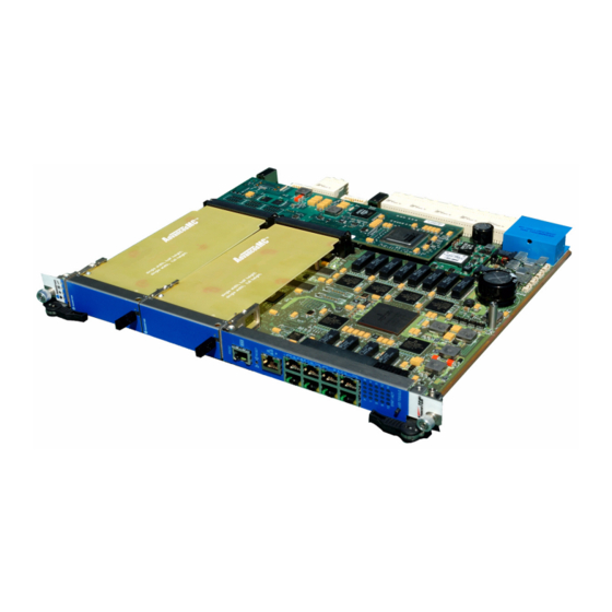
- Page 1 AT8901 USER GUIDE AdvancedTCA M5301_TECH_2 Manual ID 1.0 Revision Index 1 June, 2006 Date of Issue...
-
Page 2: Revision History
Disclaimer Copyright © 2006 Kontron AG. All rights reserved. All data is for information purposes only and not guaranteed for legal purposes. Information has been carefully checked and is believed to be accurate; however, no responsibility is assumed for inaccuracies. Kontron and the Kontron logo and all other trademarks or registered trademarks are the property of their respective own- ers and are recognized. -
Page 3: Table Of Contents
1.3 Software Support ................... 1 - 11 Chapter Installation ....................2 - 2 2.1 Safety Requirements ................2 - 2 2.2 AT8901 Initial Installation Procedures ............. 2 - 3 2.3 Standard Removal Procedures ............... 2 - 4 2.4 AMC Installation ..................2 - 4 Page iii... - Page 4 Management ................... 4 - 2 4.1.2 Switching ..................4 - 4 4.1.3 Routing ................... 4 - 5 4.1.4 QoS ....................4 - 6 4.2 Supported MIBs ..................4 - 6 4.2.1 Enterprise MIB ................4 - 6 Page iv AT8901 User Guide...
- Page 5 4.5 Firmware Administration ............... 4 - 17 4.5.1 Startup Configurations ..............4 - 18 4.5.2 Updating Firmware ............... 4 - 19 4.5.3 Updating IPMI ................4 - 22 Appendix A. Getting Help ....................A - 2 Page v AT8901 User Guide...
- Page 6 List of Tables Fabric Interface Options ................1 - 6 Base Interface Options ................1 - 6 AT8901 Main Specifications ............... 1 - 7 AT8901 Software Specification ..............1 - 11 PCI Slots ....................3 - 3 Fast Ethernet Management (RJ45) Pin Assignment ........3 - 4 Fast Ethernet Management (RJ45) LEDs Signification ......
- Page 7 Functional Block Diagram Base Board ............3 - 2 Block Diagram AMC GbE Cross-connect via update channels ....3 - 8 Front Panel of AT8901 ................3 - 18 Symbols Chart ..................3 - 19 Backplane Switch LEDs Signification ............3 - 20...
-
Page 8: Proprietary Note
Kontron AG reserves the right to change, modify, or improve this document or the product de- scribed herein, as seen fit by Kontron AG without further notice. -
Page 9: Explanation Of Symbols
However, the life expectancy of your product can be drastically reduced by improper treatment during unpacking and installation. Therefore, in the interest of your own safety and of the correct operation of your new Kontron product, you are requested to conform with the following guidelines. -
Page 10: High Voltage Safety Instructions
ROM devices, jumper settings etc. If the product contains batteries for RTC or memory back-up, ensure that the board is not placed on conductive surfaces, including anti-static plas- tics or sponges. They can cause short circuits and damage the batteries or conductive circuits on the board. Page xi AT8901 User Guide... -
Page 11: General Instructions On Usage
Preface General Instructions on Usage In order to maintain Kontron’s product warranty, this product must not be altered or modified in any way. Changes or modifications to the device, which are not explicitly approved by Kontron AG and described in this manual or received from Kontron’s Technical Support as a special handling instruction, will void your warranty. -
Page 12: Two Year Warranty
As a result, the products are sold “as is,” and the responsibility to ensure their suit- ability for any given task remains that of the purchaser. In no event will Kontron be liable for direct, indirect or consequential damages resulting from the use of our hardware or software products, or documentation, even if Kontron were advised of the possibility of such claims prior to the purchase of the product or during any period since the date of its purchase. -
Page 13: Introduction
AT8901 Introduction Chapter Introduction Page 1 - 1 AT8901 User Guide... -
Page 14: Product Overview
LVL7 software suite. Management The AT8901 is managed either in-band or out of band via 10/100 Ethernet or RS232 manage- ment ports. The comprehensive set of supported protocols rounds out the feature set of Kon- trons' second generation AdvancedTCA Hub Board. -
Page 15: At8901 Features
• Out of band via Ethernet or RS232 • IPMI version 1.5 • Ethernet/Bridging protocols include • Link aggregation (802.3ad) • VLANs (802.1Q) • Spanning tree (802.1D, 802.1w) • QoS (802.1p) • Flow control (802.3x) • GVRP, GMRP Page 1 - 3 AT8901 User Guide... -
Page 16: General Compliances
• RIPv2 • VRRP • DiffServ • ARP 1.1.2 General compliances The AT8901 conforms to the following specifications: • PICMG 3.0 AdvancedTCA Base Specification, Revision 2.0 • AMC.0 AMC Base Specification • AMC.2 AMC Gigabit Ethernet / 10 Gigabit XAUI Ethernet •... -
Page 17: Board Layout
AT8901 Introduction 1.1.3 Board Layout The following figure shows a top view of the AT8901 board. Figure 1-1: AT8901 Board MTG1 MTG2 MTG3 MTG4 ANC1 R1400 R1377 R1368 R1414 R1350 R1415 R1413 U138 U129 U128 U125 U141 U123 U126 U112... -
Page 18: Optional Accessories
(without powering-down the system). Please refer to the PICMG 3.0 R1.0 specification for additional details. 1.1.6 Board Options The Kontron ATCA Hub family is available with different Fabric Mezzanine options: Table 1-1: Fabric Interface Options Product... -
Page 19: Technical Specification
AT8901 Introduction Technical Specification Table 1-3: AT8901 Main Specifications AT8901 SPECIFICATIONS • PowerPC IBM PPC 405 IBM PowerPC 405 32-bit RISC processor core operating up to 400MHz with ® 16KB I- and D-caches GPr 400MHz • PC-133 synchronus DRAM (SDRAM) interface •... - Page 20 AT8901 Introduction Table 1-3: AT8901 Main Specifications (Continued) AT8901 SPECIFICATIONS • Broadcom 5650x/5630x 24 10/100/1000 Mbps Ethernet ports GbE Switch • Fifth generation of StrataSwitch and StrataXGS product line • Line-rate switching for all packet sizes and conditions • On-chip data packet memory and table memory •...
- Page 21 AT8901 Introduction Table 1-3: AT8901 Main Specifications (Continued) AT8901 SPECIFICATIONS • Mechanical 8U form factor mechanically compliant to PICMG 3.0 • Single Slot (6HP) • 2 standard full height/single width AMC Slots • 280 mm x 322 mm (11.024“ x 12.677“) •...
- Page 22 AT8901 Introduction Table 1-3: AT8901 Main Specifications (Continued) AT8901 SPECIFICATIONS Safety Designed to meet or exceed the following: • UL 60950, 3rd edition • EN 60950 • LVD 73/23/EEC • Denan Law Designed to meet or exceed the following: •...
-
Page 23: Software Support
AT8901 Introduction Software Support The following table contains information related to software supported by the AT8901. Table 1-4: AT8901 Software Specification SPECIFICATIONS • General Reliable field upgrades for all software components • Dual boot images with roll-back capability • Management via SNMP and Command Line Interface •... -
Page 24: At8901 Software Specification
AT8901 Introduction Table 1-4: AT8901 Software Specification (Continued) SPECIFICATIONS • Applications NTP client for retrieving accurate time and date information • DHCP server • Onboard event management • Test and trace facilities • POST (power on self tests) diagnostics •... - Page 25 AT8901 Introduction Table 1-4: AT8901 Software Specification (Continued) SPECIFICATIONS Bootloader u-boot Version 1.1.2 • POST • multi image support • loadable bootimage via network (bootp/tftp) • reliable field upgradable • H/W protected • KCS interface to IPMC • serial console support •...
-
Page 26: Installation
AT8901 Installation Chapter Installation Page 2 - 1 AT8901 User Guide... -
Page 27: Safety Requirements
Installation Installation The AT8901 has been designed for easy installation. However, the following standard precau- tions, installation procedures, and general information must be observed to ensure proper in- stallation and to preclude damage to the board, other system components, or injury to personnel. -
Page 28: At8901 Initial Installation Procedures
AT8901 Installation AT8901 Initial Installation Procedures The following procedures are applicable only for the initial installation of the AT8901 in a sys- tem. Procedures for standard removal and hot swap operations are found in their respective chapters. To perform an initial installation of the AT8901 in a system proceed as follows: 1. -
Page 29: Standard Removal Procedures
OFF at the end of the hot swap sequence. Software Installation The AT8901 comes as a pre-installed system with all necessary OS, Filesystem, drivers and applications factory-installed with default configurations. Updating the Software with new Operating System or applications or new versions is provided by a dedicated update mechanism, which is described in Chapter 4. - Page 30 IP settings. The corresponding procedure is described in the following. User input is printed in bold letters. 1. Connect to serial port on AT8901 front plate using the adapter described in Chapter 3, sec- tion 3.1.
- Page 31 (Base Fabric) # To access the CLI via Fast Ethernet management port, open a telnet connection to the config- ured IP address, port 23. For additional information on the system configuration, refer to documentation “AT8901/2/3 CLI Reference Manual“. Page 2 - 6...
-
Page 32: Hardware Description
AT8901 Hardware Description Chapter Hardware Description Page 3 - 1 AT8901 User Guide... -
Page 33: Functional Block Diagram Base Board
AT8901 Hardware Description Hardware Description The AT8901 is a PICMG 3.0 compliant Hub Board for AdvancedTCA shelves. It provides a base interface suitable for 14 and 16 slot systems. It also provides two AMC slots for custom- ization. Figure 3-1: Functional Block Diagram Base Board... -
Page 34: Cpu And Memory
AT8901 Hardware Description The main building blocks of the AT8901 are: • CPU and Memory • Base Switch • AMC Bays • IPMI • Synchronization clock • RTM Interface • Power Supply CPU and Memory The CPU is an IBM PowerPC 405 GPr 400MHz 32-bit RISC processor with 16KB D-cache. -
Page 35: Fast Ethernet Management (Rj45) Pin Assignment
The Flashes are connected to the 32 bit peripheral data bus. The PowerPC 405 GPr accesses the Flashes with CS0#. The sector containing the bootloader code is write protected. The pro- tection can be disabled by setting jumper FWPD. Page 3 - 4 AT8901 User Guide... -
Page 36: Serial Port (Rj45) Pin Assignment
DB9 Pin DB9 Female Number Number Request To Send Data Terminal Ready Transmit Ground Ground Receive Data Set Ready Front View Front View Clear To Send Ring Indicator (Not used) Carrier Detect (Not used) Page 3 - 5 AT8901 User Guide... -
Page 37: Base Switch
Uplink 4 0/10 0/11 0/12 0/13 0/14 0/15 0/16 0/17 0/18 0/19 0/20 SMCA 0/21 Local AMC B1, channel 0 0/22 Remote AMC B1, channel 1 0/23 Local AMC B2, channel 0 0/24 SMCB Page 3 - 6 AT8901 User Guide... -
Page 38: Base Uplink (J27) Pin Assignment
T quad PHY and two 10/100/1000BASE-T dual magnetics. GbE channels 0/1 to 0/4 of the switch map to uplink channels 1 to 4. The upper four RJ45 connectors on the front panel are not used for the AT8901. Table 3-7:... -
Page 39: Block Diagram Amc Gbe Cross-Connect Via Update Channels
AMC B1 and the backplane are buffered by a cross-point switch that is controlled by the IPMC. Figure 3-2: Block Diagram AMC GbE Cross-connect via update channels The block diagram shows one solution for the AMC GbE support channels with a PrAMC as System Controller. Page 3 - 8 AT8901 User Guide... -
Page 40: Amc Bays
RTM, STOR0 Fabric Fabric Fabric Fabric Fabric Fabric Fabric Fabric Extended RTM, AMC_B1_P13 Extended RTM, AMC_B1_P14 Extended RTM, AMC_B1_P15 Extended RTM, AMC_B1_P16 Extended RTM, AMC_B1_P17 Extended RTM, AMC_B1_P18 Extended RTM, AMC_B1_P19 Extended RTM, AMC_B1_P20 Page 3 - 9 AT8901 User Guide... -
Page 41: Amc B2 Channel Assignment
Local Base Switch 0/23 SATA/FC AMC B1, channel 2 SATA/FC RTM, STOR1 Fabric Fabric Fabric Fabric Fabric Fabric Fabric Fabric Extended Extended Extended Extended Extended RTM, AMC_B2_P17 Extended RTM, AMC_B2_P18 Extended RTM, AMC_B2_P19 Extended RTM, AMC_B2_P20 Page 3 - 10 AT8901 User Guide... -
Page 42: Ipmi
The main building blocks of the IPMI architecture of the AT8901 are: • IPMC Intelligent Platform Management Controller •... -
Page 43: Synchronization Clock
The three differential clock signals are buffered by three differential line drivers that are controlled by the IPMC and CPLD respectively. For further details please refer AMC specification AMC0.RC1.1. Page 3 - 12 AT8901 User Guide... -
Page 44: Rtm Interface
N.C. N.C. N.C. JTAG_TMS JTAG_ N.C. N.C. N.C. SMB_ N.C. N.C. TRST# ALERT# N.C. N.C. N.C. N.C. N.C. N.C. N.C. N.C. N.C. N.C. N.C. N.C. N.C. N.C. N.C. N.C. # Active Low Signal Page 3 - 13 AT8901 User Guide... -
Page 45: Power Supply
• Additional AMC payload power consumption: 75W 3.7.1 Power Connector The power connector supplies the board with two 48V redundant rails, digital ground and chas- sis ground. It also provides the redundant IPMB Shelf Manager connection. Page 3 - 14 AT8901 User Guide... -
Page 46: Power Distribution
The converter allows a maximum of 14A output current. Two different management voltages (3.3V and 5V) and five payload voltages (3.3V, 2.5V, 1.8V, 1.25V and 1.2V) are generated by point of load converters. These are either switches or linear regulators. Page 3 - 15 AT8901 User Guide... -
Page 47: Power Supply Amcs
In case of a 0V transient the board is able to keep the board alive for 8ms. The necessary en- ergy is buffered in a capacitor. The load time for the capacitor is 100s. Page 3 - 16 AT8901 User Guide... -
Page 48: Optional Chassis To Logic Ground Connection
3.7.6 Optional Chassis to Logic Ground Connection According to NEBS requirement R9-14 of GR-1089-CORE issue 3, the AT8901 provides a con- nection between chassis and logic ground. It is made up of a screw that connects the PCB to the bottom sheet. -
Page 49: Display Elements
AT8901 Hardware Description 3.10 Display Elements Figure 3-3: Front Panel of AT8901 ATCA LEDs Serial Port Reset Switch Ethernet Management Fabric Uplink (Not Used) Base Uplink Backplane Link LEDs LED Toggle (Not Used) Page 3 - 18 AT8901 User Guide... -
Page 50: Atca Leds Signification
On=Healthy (PPC/IPMC), Blink=Sensor out of range ATCA LED1 (OOS) (red) On=Out of Service (PPC/FUM) Blink=Firmware Update in Progress or Power denied ATCA BLUE LED (H/S) On=Ready for Hot Swap (IPMC) Blink=Hot Swap in Progress Page 3 - 19 AT8901 User Guide... -
Page 51: Backplane Link Leds Signification
Each RJ45 displays the status of the link with the two integrated LEDs. The reset switch will perform a reset on the CPU when pressed for less than 1 second and a complete board reset (including IPMI) when pressed for more than 2 seconds. Page 3 - 20 AT8901 User Guide... -
Page 52: Switch Led Assignment
ShMC (s) Ch 2 (other Hub) Ch 3 Ch 4 Ch 5 Ch 6 Ch 7 Ch 8 Ch 9 Ch 10 Ch 11 Ch 12 Ch 13 Ch 14 Ch 15 Ch 16 Page 3 - 21 AT8901 User Guide... -
Page 53: Software Description
AT8901 Software Description Chapter Software Description Page 4 - 1 AT8901 User Guide... -
Page 54: Supported Rfcs
AT8901 Software Description Software Description Software on the AT8901 includes the following parts: • Bootloader • OS (rootFS, kernel) • Application SW • IPMI FW The Software accomplishes operation of the switching hardware and is therefore also refer- enced as firmware. It is preinstalled on the system and can only be updated by a dedicated update procedure. - Page 55 • Draft-ietf-secsh-architecture-14 - SSH Protocol Architecture • Draft-ietf-secsh-publickeyfile-03 - SECSH Public Key File Format • Draft-ietf-secsh-dh-group-exchange-04 - Diffie-Hellman Group exchange for the SSH Transport Layer Protocol • Configurable Management VLAN ID • Industry Standard CLI Page 4 - 3 AT8901 User Guide...
-
Page 56: Switching
• RFC 783 - TFTP • RFC 791 - IP • RFC 792 - ICMP • RFC 793 - TCP • RFC 951 - BOOTP • RFC 1321 - Message Digest Algorithm (MD5) Page 4 - 4 AT8901 User Guide... -
Page 57: Routing
• RFC 1027 - Using ARP to implement transparent subnet gateways • RFC 1058 - RIP v1 • RFC 1256 - ICMP Router Discovery Messages • RFC 1321 - Message Digest Algorithm (MD5) • RFC 1519 - CIDR Page 4 - 5 AT8901 User Guide... -
Page 58: Qos
• RFC 3260 - New Terminology and Clarifications for DiffServ Supported MIBs The Software supports the following MIBs. 4.2.1 Enterprise MIB • Support for all managed objects not contained in standards based MIBs. Page 4 - 6 AT8901 User Guide... -
Page 59: Switching Package Mibs
• RFC 3289 - DIFFSERV-MIB & DIFFSERV-DCSP-TC MIBs Bootloader On the AT8901 Hub Board, the bootloader ‘u-boot‘ (universal bootloader) is used. The boot- loader initializes the main components of the board like CPU, SDRAM, serial lines etc. for op- eration. After this, kernel and application are started from flash. -
Page 60: Power On Self Test
In this case, a management instance can read the last postcode written via the IPMC and thus determine where the fatal error has occurred. Page 4 - 8 AT8901 User Guide... -
Page 61: Post Boot Steps
PC_PCI 0x1D PCI configuration done PC_DEVICES 0x1E Device init done PC_JUMPTABLE 0x1F Jumptable init done PC_CONSOLE 0x20 Console init done PC_MAIN 0x2F Enter main loop PC_START_OS 0x3F Pass control to OS, leave bootloader Page 4 - 9 AT8901 User Guide... -
Page 62: Ipmi Firmware
The FUM keeps two IPMC Firmware code images in two external SEEPROM memories. If a failure occurs during firmware upgrade, the FUM will auto- matically rollback to the last known working IPMC firmware image. Page 4 - 10 AT8901 User Guide... -
Page 63: Sensor Data Record (Sdr)
C On/Off Exceeds critical threshold Icc 12v FRU0 Amps Exceeds critical threshold Vcc 12v FRU0 Volts Exceeds critical threshold Icc 12v FRU1 Amps Exceeds critical threshold Icc 12v FRU2 Amps Exceeds critical threshold Page 4 - 11 AT8901 User Guide... -
Page 64: At8901 Sensors
AT8901 Software Description Table 4-3: AT8901 sensors (continued) Scanning Enabled Under IPMI Sensor Name Unit Health LED/Sensor Power State Icc 3.3vSus FRU0 Amps On/Off Exceeds critical threshold Vcc 3.3vSus FRU0 Volts On/Off Exceeds critical threshold Icc 3.3v FRU0 Amps Exceeds critical threshold Vcc 3.3v FRU0... - Page 65 IPMB bus. In the event of any link state change, the events are written to the AT8901 SEL. The IPMC monitors the bus for any link failure and isolates itself from the bus if it detects that it is causing errors on the bus. Events are sent to signal the failure of a bus or, conversely, the recovery of a bus.
-
Page 66: Field Replaceable Unit (Fru) Information
Communicates with the Firmware Upgrade Manager (FUM) in order to inform the IPMC watchdog that the current IPMC firmware is suitable for execution. Upon successful verification of the operational code checksum, the firmware will jump to the operational code. Page 4 - 14 AT8901 User Guide... -
Page 67: Leds
Out-Of-Service (OOS) LED (ATCA LED1) The AT8901 supports a red Out of Service LED mounted on the front panel. The position of this LED is near the top handle besides the blue Hot Swap led. The on-board FWUM or the IPMC can drive this LED to indicate the service state of the IPMC. -
Page 68: Hot Swap Process
4.4.6 Hot Swap Process The AT8901 Hub Board has the ability to be hot-swapped in and out of a chassis. The onboard IPMC manages the power-up and power-down transitions. In addition to captive retaining screws, the Hub Board has two ejector mechanisms to provide a positive cam action;... -
Page 69: Firmware Administration
Software Description Firmware Administration A running AT8901 system requires – after the bootloader has passed control to the kernel – the kernel itself, the root file system (initrd), the FASTPATH switching application and a config- uration file for base and fabric switch. These software components, together with the IPMC im- age, make up the AT8901 firmware. -
Page 70: Startup Configurations
CLI hierarchy, which is entered by executing the ‘enable’ command. Please refer to the “AT8901/2/3 CLI Reference Manual“ for more information regarding the CLI commands and the way to use them. -
Page 71: Updating Firmware
B kernel and root file system. The active system is either system A or system B, the factory default serves as a backup in case an upgrade of either system A or B fails. See the flash partition scheme shown above for more detail. Page 4 - 19 AT8901 User Guide... - Page 72 5. Restart the board. 6. Activate the new startup configuration permanently A software release for the AT8901 consists of three software packages for kernel, initrd and application software. The packages are tar archives containing an image of the software and a MD5 checksum file for consistency check.
- Page 73 This way, a failsafe upgrade of the AT8901 software is possible. To restart the board with the new startup configuration, the CLI command ‘reload’ is used:...
-
Page 74: Updating Ipmi
(Base Fabric) #download ipmifw tftp://192.168.50.5/ipmi.pkg Flashing a new IPMI firmware will disable the IPMI Controller for some minutes. Are you sure to update the IPMI firmware? (y/n)y (Base Fabric) # Page 4 - 22 AT8901 User Guide... -
Page 75: Appendix
AT8901 Getting Help Appendix Getting Help Page A - 1 AT8901 User Guide... -
Page 76: A. Getting Help
Tel.: +49 (0) 8341 803 333 Fax: (450) 437-8053 Fax: +49 (0) 8341 803 339 If you have any questions about Kontron, our products, or services, visit our Web site at: www.kontron.com You also can contact us by E-mail at: North America: support@ca.kontron.com... - Page 77 3. Fax it to us at: North America (450) 437-0304, EMEA +49 (0) 8341 803 339 • E-mail 1. Send us an e-mail at: RMA@ca.kontron.com in North America or at: orderprocess- ing@kontron-modular.com in EMEA. In the e-mail, you must include your name, your company name, your address, your city, your postal/zip code, your phone number, and your e-mail.
- Page 78 • Clearly write or mark the RMA number on the outside of the package you are returning. • Ship prepaid. We take care of insuring incoming units. North America EMEA Kontron Canada, Inc. Kontron Modular Computers GmbH 616 Curé Boivin Sudetenstrasse 7 Boisbriand, Québec 87600 Kaufbeuren...
- Page 79 Number: Fax Number: ________________________ E-Mail: _______________________ P.O. # Serial Number Failure or Problem Description (if not under warranty) Fax this form to Kontron’s Technical Support department in North America at (450) 437-0304 or in EMEA at +49 (0)8341 803 339...
Need help?
Do you have a question about the AT8901 and is the answer not in the manual?
Questions and answers