Table of Contents
Advertisement
Quick Links
Advertisement
Table of Contents

Related Manuals for Kontron COMe Eval Carrier T7


Summary of Contents for Kontron COMe Eval Carrier T7
- Page 1 USER GUIDE COMe Eval Carrier T7 (A2T7) Rev 1.1 Doc.-ID: 1068-1349...
- Page 2 COMe Eval Carrier T7 (A2T7) User Guide Rev 1.1 This page has been intentionally left blank www.kontron.com // 2...
-
Page 3: Disclaimer
In cases of doubt, please contact Kontron. This user guide is protected by copyright. All rights are reserved by Kontron. No part of this document may be reproduced, transmitted, transcribed, stored in a retrieval system, or translated into any language or computer language, in any form or by any means (electronic, mechanical, photocopying, recording, or otherwise), without the express written permission of Kontron. -
Page 4: Intended Use
SEVERE PHYSICAL OR ENVIRONMENTAL DAMAGE (COLLECTIVELY, "HIGH RISK APPLICATIONS"). You understand and agree that your use of Kontron devices as a component in High Risk Applications is entirely at your risk. To minimize the risks associated with your products and applications, you should provide adequate design and operating safeguards. -
Page 5: Revision History
If you have any difficulties using this user guide, discover an error, or just want to provide some feedback, contact Kontron support. Detail any errors you find. We will correct the errors or problems as soon as possible and post the revised user guide on our website. -
Page 6: Symbols
COMe Eval Carrier T7 (A2T7) User Guide Rev 1.1 Symbols The following symbols may be used in this manual DANGER indicates a hazardous situation which, if not avoided, will result in death or serious injury. WARNING indicates a hazardous situation which, if not avoided, could result in death or serious injury. -
Page 7: For Your Safety
Therefore, in the interest of your own safety and of the correct operation of your new Kontron product, you are requested to conform with the following guidelines. -
Page 8: Lithium Battery Precautions
General Instructions on Usage In order to maintain Kontron’s product warranty, this product must not be altered or modified in any way. Changes or modifications to the product, that are not explicitly approved by Kontron and described in this user guide or received from Kontron Support as a special handling instruction, will void your warranty. -
Page 9: Weee Compliance
COMe Eval Carrier T7 (A2T7) User Guide Rev 1.1 WEEE Compliance The Waste Electrical and Electronic Equipment (WEEE) Directive aims to: Reduce waste arising from electrical and electronic equipment (EEE) Make producers of EEE responsible for the environmental impact of their products, especially when the product become waste ... -
Page 10: Table Of Contents
COMe Eval Carrier T7 (A2T7) User Guide Rev 1.1 Table of Contents Disclaimer ..........................................3 Intended Use ........................................4 Revision History ........................................5 Symbols ..........................................6 For Your Safety ........................................7 High Voltage Safety Instructions .................................. 7 Lithium Battery Precautions ..................................8 General Instructions on Usage.................................. -
Page 11: List Of Tables
COMe Eval Carrier T7 (A2T7) User Guide Rev 1.1 5.20. ATX Power connector (J53) ................................38 5.21. RTC Socket (J21) ...................................... 38 5.22. DIP Switch (SW7) ....................................39 5.23. Button Switches ....................................40 5.24. Jumper ........................................41 5.24.1. Jumper (J43, J46) ....................................41 5.24.2. -
Page 12: List Of Figures
Table 35: Adapter Cards ....................................53 List of Figures Figure 1: COMe Eval Carrier T7 (A2T7) with four PCIe slots ........................ 14 Figure 2: Block Diagram COMe Eval Carrier T7 (A2T7) ......................... 19 Figure 3: Top View of COMe Eval Carrier T7 (A2T7) ..........................20 Figure 4: Front Panel ....................................... - Page 13 COMe Eval Carrier T7 (A2T7) User Guide Rev 1.1 Figure 44: Block Diagram CS4223 with 4x SFP+ interfaces ......................58 Figure 45: Block Diagram CS4227 with 2x SFP+ interfaces ....................... 59 www.kontron.com // 13...
-
Page 14: 1/ Introduction
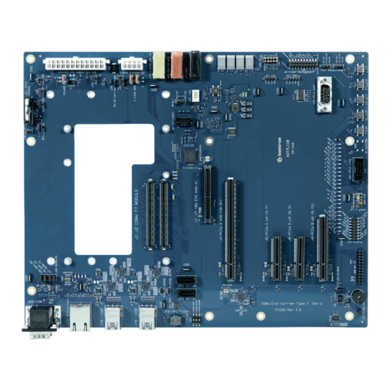
External BIOS flash socket and header for emulator connection Prepared to support BMC card + NCSI support on separate expansion Prepared to support Intelligent Platform Management Bus (IPMB) on separate expansion Figure 1: COMe Eval Carrier T7 (A2T7) with four PCIe slots www.kontron.com // 14... -
Page 15: Product Naming Clarification
1.3. Understanding COM Express® Functionality All Kontron COM Express® extended, basic and compact modules contain two 220pin connectors; each of it has two rows called Row A & B on primary connector and Row C & D on secondary connector. The COM Express® Computer- On-Module (COM) features the following maximum amount of interfaces according to the PCI Industrial Computer Manufacturers Group (PICMG) module Pin-out type. -
Page 16: Com Express® Documentation
COMe Eval Carrier T7 (A2T7) User Guide Rev 1.1 1.4. COM Express® Documentation The COM Express® Specification defines the COM Express® module form factor, pin-out, and signals. This document is available at the PICMG® website by filling out the order form. -
Page 17: 2/ System Specifications
COMe Eval Carrier T7 (A2T7) User Guide Rev 1.1 2/ System specifications 2.1. Component Main Data The table below summarizes the features of the motherboard. Table 2: Component Main Data COMe Eval Carrier T7 (A2T7) Form factor Testing Hardware with 244.0 mm x 305.0 mm... -
Page 18: Environmental Conditions
COMe Eval Carrier T7 (A2T7) User Guide Rev 1.1 2.2. Environmental Conditions Table 3: Environmental Conditions Operating -0°C to +60°C Some connectors and supercap has operating temperature only 0°C to +70°C, relative humidity (non-condensing) 10 % to 93 % at 40°C (acc. to IEC 60068-2-78) Storage -30°C to +85°C... -
Page 19: Block Diagram
COMe Eval Carrier T7 (A2T7) User Guide Rev 1.1 2.3. Block diagram Figure 2: Block Diagram COMe Eval Carrier T7 (A2T7) www.kontron.com // 19... -
Page 20: 3/ Mainboard Views
COMe Eval Carrier T7 (A2T7) User Guide Rev 1.1 3/ Mainboard Views 3.1. Top View Figure 3: Top View of COMe Eval Carrier T7 (A2T7) 6x Button Switches (SW1-SW6) 16. LPC/eSPI (J61) CPLD JTAG (2x5 pins, J56) 17. ATX power connector 4 pins (J53) Front Panel Connector (J11) 18. -
Page 21: Front Panel
COMe Eval Carrier T7 (A2T7) User Guide Rev 1.1 3.2. Front panel Figure 4: Front Panel 31. 2x UART ports (COM0-Top, COM1-Bot) 32. Ethernet (J14) 33. 4x USB (J18) www.kontron.com // 21... -
Page 22: 4/ Mechanical Specification
COMe Eval Carrier T7 (A2T7) User Guide Rev 1.1 4/ Mechanical Specification 4.1. Dimensions The dimensions of the carrier board (see Figure 5) are 244.0 mm x 305.0 mm. Figure 5: Board Dimensions www.kontron.com // 22... -
Page 23: 5/ Interfaces And Connectors
COMe Eval Carrier T7 (A2T7) User Guide Rev 1.1 5/ Interfaces and Connectors 5.1. 1 GB Ethernet Connector (J14) Figure 6: 1 GB Ethernet C onnector Table 4: 1 GB Ethernet C onnector Signal Name CT_MDI1 GBE0_MDI1- GBE0_MDI1+ GBE0_MDI2+ GBE0_MDI2-... -
Page 24: Usb 3.1 Double Connector (J68)
COMe Eval Carrier T7 (A2T7) User Guide Rev 1.1 5.2. USB 3.1 Double Connector (J68) Figure 7: USB 3.1 Double Connector Table 6: USB 3.1 Double Connector Signal Name - J17 Signal Name - J18 V_5V0_M_USB1_CONN V_5V0_M_USB3_CONN USB20_D1_CONN- USB20_D3_CONN- USB20_D1_CONN+... -
Page 25: Com Ports (J68)
COMe Eval Carrier T7 (A2T7) User Guide Rev 1.1 5.3. COM Ports (J68) Figure 8: Double COM Ports Bottom Table 7: Double COM Ports Signal Name SER0_RX_RS M0 SER0_TX_RS232_COM0 SER1_RX_RS232_COM0 SER1_TX_RS232_COM0 www.kontron.com // 25... -
Page 26: Cpld Uart (J79)
COMe Eval Carrier T7 (A2T7) User Guide Rev 1.1 5.4. CPLD UART (J79) Figure 9: CPLD UART Table 8: CPLD UART Connector Signal Name SN65_UART_RXD SN65_UART_TXD SN65_UART_DTR SN65_UART_DSR SN65_UART_RTS SN65_UART_CTS www.kontron.com // 26... -
Page 27: Ethernet Add-In Card Connector (J7)
COMe Eval Carrier T7 (A2T7) User Guide Rev 1.1 5.5. 10 GB Ethernet Add-in Card Connector (J7) The carrier board contains 10 GB Ethernet connector that supports copper and optical 10 GB interface via extended cards. Figure 10: 10 GB Ethernet Add-in Card Connector... - Page 28 COMe Eval Carrier T7 (A2T7) User Guide Rev 1.1 Signal Name Signal Name 10G_KR_RX2+ 10G_KR_RX2- 10G_SFP_SCL2 10G_KR_TX2- 10G_PHY_RST_23 10G_KR_TX2+ V_5V0_S5 V_5V0_S5 10G_PHY_RST_01 10G_PHY_CAP_23 10G_INT1 10G_INT3 10G_SDP1 10G_SDP3 10G_PHY_MDC_SCL1 10G_PHY_MDC_SCL3 10G_PHY_MDIO_SDA1 10G_PHY_MDIO_SDA3 10G_INT0 10G_INT2 10G_SDP0 10G_SDP2 10G_PHY_MDC_SCL0 10G_PHY_MDC_SCL2 10G_PHY_MDIO_SDA0 10G_PHY_MDIO_SDA2 www.kontron.com...
-
Page 29: Sata 6 Gb (J15, J16)
COMe Eval Carrier T7 (A2T7) User Guide Rev 1.1 5.6. SATA 6 GB (J15, J16) Figure 11: SATA 6 GB Table 10: SATA 6 GB Connector Signal Name - J15 Signal Name – J16 SATA0_TX+ SATA1_TX+ SATA0_TX- SATA1_TX- SATA0_RX+ SATA1_RX+... -
Page 30: Nc-Si Connector (J80)
COMe Eval Carrier T7 (A2T7) User Guide Rev 1.1 5.8. NC-SI Connector (J80) Figure 12: NC-SI Connector Table 12: NC-SI Connector Pinning Signal Name V_3V0_RTC V_3V3_S5 NCSI_ARB_OUT V_5V0_S5 NCSI_RXD1 V_5V0_S5 NCSI_RXD0 NCSI_TXD0 I2C_CLK NCSI_TXD1 I2C_DAT NCSI_TX_EN NCSI_CRS_DV NCSI_CLK_IN NCSI_RX_ERR NCSI_ARB_IN... -
Page 31: Fan Connector (J47)
COMe Eval Carrier T7 (A2T7) User Guide Rev 1.1 5.9. Fan Connector (J47) Figure 13: Fan Connector with 4 pins Table 13: Fan Connector Description V_FAN FAN_TACH_CON FAN_PWM_CON 5.10. BIOS Flash Socket (J19) Figure 14: BIOS Flash Socket Table 14: BIOS Flash Socket Pinout... -
Page 32: Spi Connector (J62)
COMe Eval Carrier T7 (A2T7) User Guide Rev 1.1 5.11. SPI Connector (J62) Figure 15: SPI Connector with 8 pins Table 15: SPI Connector Signal Name SPI_CS# SPI_VCC SPI_MISO SPI_HOLD# SPI_WP# SPI_CLK SPI_MOSI 5.12. GPIO - General Purpose Input and Output (J20) The COMe-bBD7 offers four General Purpose Input (GPI) pins and four General Purpose Output (GPO) pins. -
Page 33: Ipmb Header (J85)
COMe Eval Carrier T7 (A2T7) User Guide Rev 1.1 Signal Name 5.13. IPMB Header (J85) Figure 17: IPMB Header with 4 pins Table 17: Pinning IPMB Header Description V_3V3_S5 IPMB_DAT IPMB _CLK 5.14. Power Management Header (J8) Figure 18: Power Management Header... -
Page 34: Status Signal Header (J10)
COMe Eval Carrier T7 (A2T7) User Guide Rev 1.1 Signal Name SYS_RESET_R# THRM_R# THRMTRIP# SATA_ACT# 5.15. Status Signal Header (J10) Figure 19: Status Signal Header Table 19: Status Signal Header Signal Name FAN_PWMOUT FAN_TACHIN PWR_OK SUS_STAT#_ESPI_RESET# CB_RESET# SUS_S3# GBE0_SDP SUS_S4#... -
Page 35: Front Panel Connector (J11)
COMe Eval Carrier T7 (A2T7) User Guide Rev 1.1 5.16. Front Panel Connector (J11) Figure 20: Front Panel Connector Table 20: Front Panel Connector Signal Name SATA_LED+ POWER_LED+ SATA_ACT# SYS_RESET_R# V_5V0_S0 5.17. I2C (J51) The I2C Interface supports clock from 127 Hz to 400 kHz (limited by on board devices and capacitive loading) and can be configured in Setup. -
Page 36: Smbus (J52)
COMe Eval Carrier T7 (A2T7) User Guide Rev 1.1 5.18. SMBus (J52) Figure 22: SMBus header with five pins Table 22: SMBus Header (J52) Description V_V3V_S5 SMB_DAT SMB_CLK SMB_ALERT# www.kontron.com // 36... -
Page 37: Atx Power Connector (J54)
COMe Eval Carrier T7 (A2T7) User Guide Rev 1.1 5.19. ATX Power connector (J54) Figure 23: ATX Power connector with 24 pins Table 23: ATX Power connector with 24 pins Signal Cable Colour 3,3 V Orange 3,3 V Orange Black... -
Page 38: Atx Power Connector (J53)
COMe Eval Carrier T7 (A2T7) User Guide Rev 1.1 5.20. ATX Power connector (J53) Figure 24: ATX Power connector with 8 pins Table 24: ATX Power connector with 8 pins Signal +12 V +12 V +12 V +12 V 5.21. RTC Socket (J21) -
Page 39: Dip Switch (Sw7)
COMe Eval Carrier T7 (A2T7) User Guide Rev 1.1 5.22. DIP Switch (SW7) Figure 26: DIP Switch (Default) Table 26:Function Table DIP Switch Notes Carrier Module Module MAFS on Module LPC bus enabled Module Carrier Carrier MAFS on Carrier LPC bus... -
Page 40: Button Switches
COMe Eval Carrier T7 (A2T7) User Guide Rev 1.1 5.23. Button Switches Figure 27: Button Switches Table 27: LEDs Button Switch Function POWER SLEEP LID (Lid) THRM (Thermal) R.SHTON (Rapid Shutdown) RESET Rapid shutdown requires disconnecting V_WIDE_S0_MOD and V_5V0_S5_MOD rails externally. -
Page 41: Jumper
COMe Eval Carrier T7 (A2T7) User Guide Rev 1.1 5.24. Jumper 5.24.1. Jumper (J43, J46) Figure 28: Jumper J43, J46 Table 28: Jumper J43, J46 Jumper Position Function description (Default) J43 (closed) USB_HOST J46 (closed) TPM_PP Module USB client may detect the presence of a USB host on USB0. A high value indicates that a host is present. -
Page 42: Jumper (J27, J28, J30)
COMe Eval Carrier T7 (A2T7) User Guide Rev 1.1 5.24.2. Jumper (J27, J28, J30) Figure 29: Jumper 27 to 30 Table 29: Jumper 27 to 30 Jumper Position Function description (Default) J27 (closed) SER0_TX J28 (closed) SER0_RX J30_SER1_TX (closed) SER1_TX... -
Page 43: Jumper (V5_Mod, J75, J31, J35, V_Wide)
COMe Eval Carrier T7 (A2T7) User Guide Rev 1.1 5.24.4. Jumper (V5_MOD, J75, J31, J35, V_WIDE) Figure 31: Jumper J22-23 Table 31: Jumper J22-23, J24-25, J31, J35 Jumper Position (Default) Function description V_Wide_MOD (both closed) V_WIDE_S0_IN V5_MOD (closed) V_WIDE_S0_MOD J75 (closed) -
Page 44: 6/ Electrical Specification
COMe Eval Carrier T7 (A2T7) User Guide Rev 1.1 6/ Electrical Specification 6.1. Supply Voltage one ATX Main Power 24pin Power supply for the module: the ATX_12V P4 connector provides a wide range of input, depending on module specification. -
Page 45: Figure 32: Power Supply Atx 24-Pin For Carrier Board (J54)
COMe Eval Carrier T7 (A2T7) User Guide Rev 1.1 Figure 32: Power Supply ATX 24-pin for Carrier Board (J54) www.kontron.com // 45... -
Page 46: 7/ Features
7/ Features 7.1. Rapid Shutdown (SW5) Kontron has implemented a rapid shutdown function. It works as follows: An active-high shutdown signal is asserted by the COMe Eval Type T7 carrier board through button switch SW5. The characteristics of the shutdown signal are as follows: ... -
Page 47: Leds And Indicators
COMe Eval Carrier T7 (A2T7) User Guide Rev 1.1 7.2. LEDs and Indicators Indicators and LEDs indicate only presence of voltage on certain signal, but not necessarily a correct shape and level of the voltage. This is important especially for power supplies – power good signal would provide more accurate indication, but it is not possible to provide this for all signals (for example ATX power signals share one power good). - Page 48 COMe Eval Carrier T7 (A2T7) User Guide Rev 1.1 Reference Indicator Color A Color B designator CPLD LED0 [OFF] Debug inactive [Yellow] Debug active CPLD LED1 [OFF] Debug inactive [Yellow] Debug active www.kontron.com // 48...
-
Page 49: 8/ Come Connector Pin-Out List
COMe Eval Carrier T7 (A2T7) User Guide Rev 1.1 8/ COMe Connector Pin-out List Figure 34: COMe Connector with 220 pins This table lists the pins and signals according to the PICMG specification COM.0 Rev 3.0 Type 7 standard. Figure 35: COMe Connector Pinout... - Page 50 COMe Eval Carrier T7 (A2T7) User Guide Rev 1.1 Signal Name Signal Name Signal Name Signal Name LPC_CLK_ESPI_C USB31_SSTX2 GBE0_MDI1+ USB31_SSRX2+ USB31_SSTX3 GBE0_MDI0- PWRBTN# USB31_SSRX3- USB31_SSTX3 GBE0_MDI0+ SMB_CLK USB31_SSRX3+ GBE0_CTREF SMB_DAT 10G_PHY_MDC_S 10G_PHY_MDI SUS_S3# SMB_ALERT# O_SDA3 10G_PHY_MDC_S 10G_PHY_MDI SATA0_TX+ SATA1_TX+...
- Page 51 COMe Eval Carrier T7 (A2T7) User Guide Rev 1.1 Signal Name Signal Name Signal Name Signal Name 10G_PHY_MDC_S 10G_PHY_MDI USB20_D0+ USB20_D1+ O_SDA0 V_3V0_RTC ESPI_EN# 10G_INT0 10G_INT1 USB_HOST_PRS GBE0_SDP SYS_RESET# 10G_KR_RX0+ 10G_KR_TX0+ LPC_SERIRQ_ES CB_RESET# 10G_KR_RX0- 10G_KR_TX0- PI_CS1# PCIE_TX5+ PCIE_RX5+ PCIE_RX16+ PCIE_TX16+...
- Page 52 COMe Eval Carrier T7 (A2T7) User Guide Rev 1.1 Signal Name Signal Name Signal Name Signal Name CLK_100M_PE_ BIOS_DIS1# PCIE_RX27+ PCIE_TX27+ REFCLK+ CLK_100M_PE_ NCSI_RX_ERR PCIE_RX27- PCIE_TX27- REFCLK- V_SPI_POWER NCSI_CLK_IN PCIE_RX28+ PCIE_TX28+ SPI_MISO NCSI_RXD1 PCIE_RX28- PCIE_TX28- GPIO_GPO0 NCSI_RXD0 SPI_CLK NCSI_CRS_DV PCIE_RX29+...
-
Page 53: 9/ Adapter Cards
COMe Eval Carrier T7 (A2T7) User Guide Rev 1.1 9/ Adapter Cards Table 35: Adapter Cards Product Number Adapter Card Description 68301-0000-04-4 Adapter Card ADA-COMe-T7- Direct connection 10G SFP adapter card for COMe T7 G2 4x 10G DAC – DEV-TOOL... -
Page 54: Figure 38: Block Diagram
COMe Eval Carrier T7 (A2T7) User Guide Rev 1.1 Figure 38: Block Diagram www.kontron.com // 54... -
Page 55: Adapter Card Ada-Come-T7-G2 4X 10G Rj45 - Dev-Tool (A2X5)
COMe Eval Carrier T7 (A2T7) User Guide Rev 1.1 9.2. Adapter Card ADA-COMe-T7-G2 4x 10G RJ45 - DEV-TOOL (A2X5) Figure 39: Top View Adapter Card A2X5 Figure 40: IOs www.kontron.com // 55... -
Page 56: Figure 41: Block Diagram
COMe Eval Carrier T7 (A2T7) User Guide Rev 1.1 Figure 41: Block Diagram www.kontron.com // 56... -
Page 57: Adapter Cards Ada-Come-T7-G2 2X 10G Sfp+ - Dev-Tool (A2In)/Ada-Come-T7-G2 4X 10G Sfp+ - Dev-Tool (A2In)
COMe Eval Carrier T7 (A2T7) User Guide Rev 1.1 9.3. Adapter Cards ADA-COMe-T7-G2 2x 10G SFP+ - DEV-TOOL (A2IN)/ADA-COMe-T7- G2 4x 10G SFP+ - DEV-TOOL (A2IN) Figure 42: Top View Adapter Card A2IN Figure 43: IOs www.kontron.com // 57... - Page 58 COMe Eval Carrier T7 (A2T7) User Guide Rev 1.1 Figure 44: Block Diagram CS4223 with 4x SFP+ interfaces www.kontron.com // 58...
- Page 59 COMe Eval Carrier T7 (A2T7) User Guide Rev 1.1 Figure 45: Block Diagram CS4227 with 2x SFP+ interfaces www.kontron.com // 59...
-
Page 60: 10/ Technical Support
RMA number. The buyer accepts responsibility for all freight charges for the return of goods to Kontron's designated facility. Kontron will pay the return freight charges back to the buyer's location in the event that the equipment is repaired or replaced within the stipulated warranty period. Follow these steps before returning any product to Kontron. - Page 61 COMe Eval Carrier T7 (A2T7) User Guide Rev 1.1 Goods returned to Kontron Europe GmbH in non-proper packaging will be considered as customer caused faults and cannot be accepted as warranty repairs. Include the RMA-Number with the shipping paperwork and send the product to the delivery address provided in the RMA form or received from Kontron RMA Support.
-
Page 62: List Of Acronyms
COMe Eval Carrier T7 (A2T7) User Guide Rev 1.1 List of Acronyms ACPI Advanced Configuration & Power Interface COMe COM Express® - Computer on Module Express ElectroMagnetic Compatibility IPMB Intelligent Platform Management Bus Management Engine NC-SI Network controller sideband interface... - Page 63 About Kontron – Member of the S&T Group Kontron is a global leader in IoT/Embedded Computing Technology (ECT). As part of the S&T technology group, Kontron offers individual solutions in the areas of Internet of Things (IoT) and Industry 4.0 through a combined portfolio of hardware, software and services. With its standard and customized products based on highly reliable state-of-the-art technologies, Kontron provides secure and innovative applications for a wide variety of industries.
Need help?
Do you have a question about the COMe Eval Carrier T7 and is the answer not in the manual?
Questions and answers