
Subscribe to Our Youtube Channel
Related Manuals for Gooxi R Series


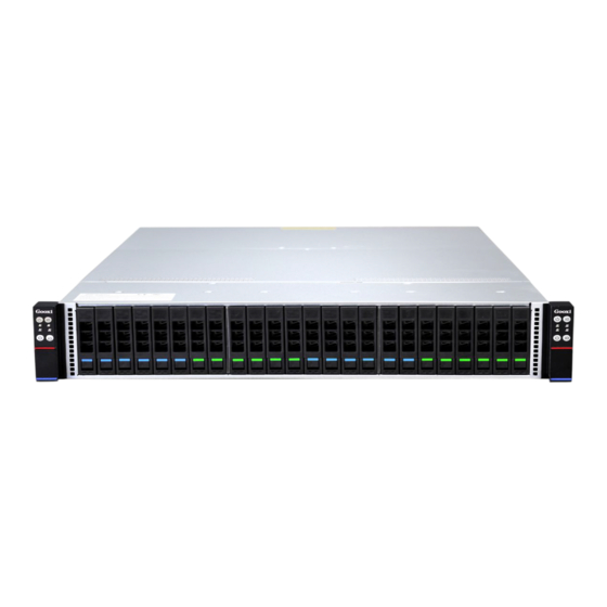
Summary of Contents for Gooxi R Series
- Page 1 SY204-D24R Series R/RF/RS/RFS/RFN 双路高密度服务器准系统 Dual Processors High Density Server Barebone 用户操作手册 User Manual Rev1.0 深圳市国鑫恒运信息安全有限公司...
- Page 2 Product. This High Density Server developed by Shenzhen Guoxin Hengyu Technology Co., Ltd. (Gooxi) supports 4 dual-processor server nodes. This System is based on an integration of the 2U four-node 24-bay chassis and the G1DCN SERIES motherboard.
- Page 3 手册构架 Framework of This User Manual 第一章 产品介绍 Chapter I Introduction to this Product 章节提供了系统主要部件的规格并对 G1DCN SERIES 主板及 2U 四节点 24 盘位机箱的 主要特性进行描述。 This Chapter presents specifications of main parts of this System and describes main characteristics of the G1DCN SERIES motherboard and the 2U four-node 24-bay chassis. 第二章...
-
Page 4: Table Of Contents
目录 Contents ................5 第一章产品介绍 Chapter I Introduction to This Product ....................5 1.1 系统特性 System characteristics ..................7 1.2 主板特性 Characteristics of motherboard ............ 9 1.3 服务器机箱系统特性 System characteristics of the server chassis ......................10 1.4 系统视图 System view ............. -
Page 5: 第一章产品介绍 Chapter I Introduction To This Product
第一章产品介绍 Chapter I Introduction to This Product 1.1 系统特性 System characteristics 1.1.1 系统参数 System parameters Model SY204-D24R SERIES Intel Xeon processor E5-2600 V3/V4 series 处理器 Socket H3 (LGA2011) up to 145W CPU 虚拟云桌面 3D 渲染制作 金融分析 关键应用 环境评估 生物科学研究 大数据挖掘 采用... - Page 6 High density, high performance, low cost and low power consumption. Adopt the dedicated 1,000mbps LAN for IPMI2.0. Motherboard G1DCN SERIES Chipset Intel PCH WellsBurg C612 chip Memory The signal node supports 16 ECCDDR4-1600/1866/2133 (system) RDIMM/LRDIMM memories. Extension Support 1 PCI-EX16 full height extension card. card SATA Support RAID 0,1,10,5 (Windows Only).
-
Page 7: 主板特性 Characteristics Of Motherboard
The System is equipped with the 1600W1+1 redundant power unit (Platinum Efficiency) and supports hot swapping. 系统采用 4 个非热插拨 8038 风扇。 The System is equipped with 4 non-hot-swappable 8038 fans. Chipset 采用 Intel PCH C612 芯片。 Intel PCH C612 chips consist of the chipset. 单节点支持... - Page 8 in total, and therefore it can support the maximum 512GB DDR4 RDIMM and the maximum 1,024GB LRDIMM. 以下为 G1DCN SERIES 的主要特性: Main characteristics of G1DCN SERIES are listed as follows: G1DCN SERIES 主板 Intel Xeon processor E5-2600 V3/V4 series 处理器 Socket H3 (LGA2011) up to 145W CPU Intel PCH WellsBurg C612 芯片...
-
Page 9: 服务器机箱系统特性 System Characteristics Of The Server Chassis
支持滑轨 选配 机柜固定方式 松不脱螺丝 优质 SGCC(镀锌钢板) 产品材质 760mm * 444mm * 88mm (长*宽*高) 机箱尺寸 1122*730*277 (长*宽*高) 包装尺寸 CE、ROHS 安规认证 Basic parameters Type Rack type Structure Applicable motherboard Gooxi G1DCN SERIES Support hot-swappable 深圳市国鑫恒宇科技有限公司 Shenzhen Guoxin Hengyu Technology Co., Ltd. 深圳市国鑫恒运信息安全有限公司... -
Page 10: 系统视图 System View
Cooling system 4 8038 temperature-controlled fans Support slide rail Option Fixation tool Captive screws Product material High-quality SGCC (galvanized steel sheet) Chassis dimension 760mm * 444mm * 88mm (length * width * height) Carton dimension 1122 * 730 * 277 (length * width * height) Certification CE, ROHS 1.3.2 系统电源... - Page 11 1.4.2 后视图 Rear view 图片仅供参考 This photo is for reference only. 1.4.3 前面板指示灯图 Schematic diagram for indicators on the front panel 上图为前面板各模块的 LED 指示灯,每个 LED 有其自己显示的状态,描述如下表: The above diagram shows LED indicators of each module on the front panel. Each LED indicator has its own display status as described in the following table.
- Page 12 LED 状态描述 LED 外观 序号 图片 描述 Node4 指示灯 ① 设备开机状态 Node4 系统身份 ID 指示灯 ② 蓝色灯常亮 Node3 指示灯 ③ 设备开机状态 Node3 系统身份 ID 指示灯 ④ 蓝色灯常亮 Nod2 指示灯 ⑤ 设备开机状态 Node2 系统身份 ID 指示灯 ⑥ 蓝色灯常亮 Node1 指示灯 ⑦ 设备开机状态...
- Page 13 Nod2 indicator Power-on status of equipment ⑤ The blue indicator keeps ID indicator of Node2 system ⑥ Node1 indicator Power-on status of equipment ⑦ The blue indicator keeps ID indicator of Node1 system ⑧ The blue indicator keeps Hard disk location indicator; ⑨...
-
Page 14: 第二章系统接口介绍 Chapter Ii Introduction To System Interfaces
第二章系统接口介绍 Chapter II Introduction to System Interfaces 2.1 概述 Overview 系统的主要接口都分布在主板上,以下内容主要介绍主板的接口布局。 Main interfaces of the System are distributed on the motherboard. Layout of interfaces on the motherboard is described as follows. 2.1.1.1 G1DCN SERIES 主板实物图片 Photo of G1DCN SERIES motherboard 2.1.1.2 G1DCN SERIES 主板接口及定义:... - Page 15 2. 主板接口定义: Definitions of interfaces on motherboard: G1DCN SERIES 单板 Connector Connector 序号 描述 备注 15PIN 的 VGA Connector 用来接入 VGA 显 示器 LED-POWER Button(带双 色指 示灯 的开 关 绿、黄色 按钮) 双口 USB3.0 Connector 自适应 1000M、 IPMI LAN 千兆网口(IPMI 专用) 100M、10M 自适应...
- Page 16 CPU1 Slot2 来自 CPU1 PCIE X8SLOT,信号采用标准链接 PCIEX8 CPU1 Slot1 来自 CPU1 PCIE X16SLOT,信号采用标准链接 PCIEX16 SATA0 7PinSATA3.0 Connector SATA1 7PinSATA 3.0 Connector SATA2 7PinSATA 3.0 Connector SATA3 7PinSATA 3.0 Connector SYS_FAN1 系统 4 针温控风扇 SYS_FAN2 Wafer-3PIN Connector UARTConnector SYS UART Wafer-3PIN Connector Connector SATA_PWR1 HDD POWER...
- Page 17 CPU2-DIMMH2 CPU2 内存通道 H,第 2 个 DIMM SLOT CPU1 CPU1 Socket CPU2 CPU2 Socket USB3 USB3.0 Type Connector GPU_PWR1 8Pin GPU 显卡 1 电源连接器 GPU_PWR2 6Pin GPU 显卡 2 电源连接器 Node ID LED 用来定位节点指示灯 系统状态指示灯,反映系统状态 D12, D13 2 个 SFP+光口指示灯 G1DCN SERIES Single-plate Connector S/N of Connector Description...
- Page 18 ME UPDATE, 2Pin jumper cap used for upgrading ME JCMOS1 2Pin jumper cap used for clearing CMOS BMC UART 3Pin BMC Debug RS232 Connector BMC Heart LED Power status indicator SYS UART 3Pin System Debug RS232 Connector JBAT1 CR2032 Battery Socket Memory channel A of CPU1, the first DIMM CPU1-DIMMA1 SLOT...
-
Page 19: 主板 Io 接口 Io Interfaces On Motherboard
2.2 主板 IO 接口 IO interfaces on motherboard 2.2.1 系统 ID(身份)指示灯 System ID indicator 系统 ID 指示灯设计是为了让用户能够更直观的识别当前操作在哪一台上面,它在主板 的具体位置如下所示,在主板的正面,标印为 D11 位置: The system ID indicator is designed to help the user recognize the operating unit in a more visual way. Its specific location on the front panel of the motherboard is shown in the following schematic diagram with the mark “D11”. - Page 20 D10: D10: BMC 指示灯 BMC indicator 2.2.4 IPMI LAN 端口 IPMI LAN port 该网口为 IPMI 专用(IPMI LAN 位置) ,用来 IPMI 远程管理使用,用 CAT5 及其以上 线缆接入交换机,也可以直接连接到客户的主机,支持千兆、百兆,且自适应调节,但是不 能作为业务数据网口使用,该网口的 LED 指示灯如下所示: This port is dedicated for IPMI (see IPMI LAN location). It is used to conduct remote management and use of IPMI.
- Page 21 IPMI LAN Port LED 描述 为 Link 状态指示灯: 1.千兆 Link,绿色长亮 Left LED 2.百兆 Link,橙色长亮 3.十兆 Link, LED 不亮 当有数据活动时,黄色指示灯闪烁 Right LED 当没有数据活动时,该指示灯不亮 IPMI LAN Port LED Description Indicator of Link status: 1. Under 1Gbps Link, the green light keeps on; Left LED 2.
- Page 22 following schematic diagram. 业务数据 LAN Port Led 描述 为 Link 状态指示灯: 1.千兆 Link,绿色长亮; Left Led 2.百兆 Link,橙色长亮; 3.十兆 Link, LED 不亮; 当有数据活动时,黄色指示灯闪烁; Right Led 当没有数据活动时,该指示灯不亮; Business Data LAN Port Led Description Indicator of Link status: 1. Under 1Gbps Link, the green light keeps on; Left Led 2.
- Page 23 * 图片仅供参考 * This schematic diagram is for reference only. 2.2.6 SFP+光口 SFP+ optical port 主板提供两个万兆网口(SFP1,SFP2 位置) ,主板集成了 JL82599ES 万兆光口芯片, 用来接收/发送业务数据,也可以直接连接到客户的主机,该网口的 LED 指示灯(D12,D13) 如下所示: The motherboard provides two 10G ports (see locations marked with SFP1 and SFP2). The motherboard integrates the JL82599ES 10G optical port chip. These ports are used to receive/send business data.
- Page 24 Note: Indicators of these two ports are the same. 网口位置示意图: Schematic diagram for locations of these ports: 10Gbps optical port1 万兆光口 1 10Gbps optical port2 万兆光口 2 * 图片仅供参考 * This schematic diagram is for reference only. 2.2.7 USB 接口 USB connector 两个外置...
- Page 25 2.2.8 VGA 显示接口 VGA display connector 主板的显卡芯片采用 AST2400, AST2400 内置 PCIE VGA Controller, 一个 15PIN 的 VGA Connector 用来接入 VGA 显示器,输出主机信息,位置示意图如下: The AST2400 chip with a built-in PCIE VGA Controller is used as the display card chip of the motherboard. The 15PIN VGA Connector is used to connect the VGA display and output the information of host.
- Page 26 SATA Connector Pin 定义 PIN 序列 描述 PIN1 Ground PIN2 SATA HOST TX+ PIN3 SATA HOST TX- PIN4 Ground PIN5 SATA HOST RX- PIN6 SATA HOST RX+ PIN7 Ground Definition of SATA Connector Pin S/N of PIN Description PIN1 Ground 深圳市国鑫恒宇科技有限公司...
- Page 27 PIN2 SATA HOST TX+ PIN3 SATA HOST TX- PIN4 Ground PIN5 SATA HOST RX- PIN6 SATA HOST RX+ PIN7 Ground 2.2.10 SATA DOM POWER CONNECTOR(DOM_PWR1 位置) SATA POWER CONNECTOR (DOM_PWR1 location) 该主板设计预留 3PIN Power Connector ,用于 SATA DOM 接入电源使用。 The motherboard is designed with 3 reserve PIN Power Connectors which are used to connect the SATA DOM to the power unit.
- Page 28 2.2.12 DIMM SLOT 介绍 DIMM SLOT 该主板设计,有 16 根 DDR4 Slot, 分为 Channel A,Channel B,Channel C,Channel D, Channel E , Channel F , Channel G , Channel H. 其 中 每 个 通 道 有 2 个 DIMM Slot. 深圳市国鑫恒宇科技有限公司 Shenzhen Guoxin Hengyu Technology Co., Ltd. 深圳市国鑫恒运信息安全有限公司...
- Page 29 DIMMA1/DIMMA2 为 Channel A DIMM 插槽; DIMMB1/DIMMB2 为 Channel B 插槽。根据 CPU 类型分为两组,每组 8 个 DIMM,CPU1 和 CPU2。 The motherboard is designed with 16 DDR4 slots which are included into Channel A, Channel B, Channel C, Channel D, Channel E, Channel F, Channel G and Channel H. Each channel contains 2 DIMM slots.
-
Page 30: 连接电缆 Connection Cable
CPU SOCKET 本主板具有两个 LGA2011 CPU Socket, 用来装入 LGA2011 的 CPU. 安装 CPU 过程中, 需要注意第 1PIN 的安装。第 1PIN 如下所示:下图红色圆圈所示为第 1PIN,有三角箭头指 示,以对应 CPU 的三角箭头。 The motherboard is provided with two LGA2011 CPU sockets which are used to hold LGA2011 CPU. In the installation of CPU, the installation of the first PIN shall be paid attention to. -
Page 31: 跳线设置 Jumper Setting
All system structures are of no cable design, and they are connected through high-speed signal terminals and adapter plates. 2.4 跳线设置 Jumper setting G1DCN SERIES 主板内有 3 个 2PIN 插针,下面的图表是这些 2PIN 的插针的区别及其 功能介绍: The G1DCN SERIES motherboard contains 3 2PINs. Distinctions and functions of these 2PINs are introduced through the following schematic diagram and table. -
Page 32: 电源模块 Power Module
G1DCN SERIES 单板 2PIN 插针使用 2PIN 插针序号 描述 默认设置 ME UPDATE 不需要插入跳线帽 ME Recovery 不需要插入跳线帽 JCMOS1 CMOS Clear 不需要插入跳线帽 Use of G1DCN SERIES Single-plate 2PIN S/N of 2PINs Description Default setting ME UPDATE Insertion of jumper cap is not required. ME Recovery Insertion of jumper cap is not required. - Page 33 LED 状态描述 LED 外观 描述 绿灯常亮 电源模块是正常运行 橙灯常亮 电源模块报警,可能过温,过压,过流,或风扇故障出现 不亮或灭的 交流电源未连接到电源模块 Description of LED Status LED appearance Description Green light keeps The power module is in normal operation. Orange light keeps The power module gives an alarm which may happen in case of over temperature, over voltage, over current or fan failures.
-
Page 34: 第三章详细的节点安装 Chapter Iii Detailed Node Installation Steps
第三章详细的节点安装 Chapter III Detailed Node Installation Steps 本章介绍了系统节点上的各主要部件安装步骤,包括 CPU、散热器、内存等安装描述。 This Chapter introduces installation steps for all major parts on the system node. It also describes installation steps for CPU, heat sink and memory. 节点的后部接口示意图如下:Schematic diagram for ports on the rear panel of the node: PCI-E X16 expansion slot PCI-E X16 扩展槽位... -
Page 35: 节点抽出后内部示意图片如下:Schematic Diagram For The Internal Part After Extraction Of The Node
如果您单独购买散装 CPU,请确保您的 CPU 使用的是 Gooxi 认证的散热器。 If you purchase an in-bulk CPU separately, please ensure that the purchased CPU is provided with a heat sink certified by Gooxi. 详细安装 LGA2011 处理器步骤: Detailed installation steps of LGA2011 processor are listed as follows. - Page 36 Note: The protective cap on the CPU mounting box is used to protect pins on the slot, and therefore it can only be removed after the CPU installation is finished. Non-adjustable wrench 固定扳手 2. 按下右侧固定扳手(D),并将其稍向左侧推(E),直到扳手脱离固定扣并轻轻抬 起固定扳手(F)。 Press down the right-side non-adjustable wrench (D) and push it leftward (E) until the wrench is separated from the fixing buckle, and then lift gently the non-adjustable wrench (F).
- Page 37 Push the left-side non-adjustable wrench towards the direction of arrow and lift the upper cap of the mounting box (G), hold firmly the cap edge, and then raise gently the upper cap. Edge of upper cap of mounting box 安装盒上盖边缘 Upper cap of mounting box 安装盒上盖...
- Page 38 Triangle marker 三角标志 5. 轻轻盖上安装盒上盖。 Close the upper cap of mounting box gently. 警告:请勿强制盖上安装盒上盖,这么做可能损坏 CPU。 Note: Do not close the upper cap of mounting box with difficulty; or otherwise, the CPU may be damaged. 6. 推下右侧固定扳手(I),确保安装盒上盖的边缘被扳手固定(J),然后将右侧固 定扳手插入固定扣下。 Push the right-side non-adjustable wrench (I), ensure that the edge of upper cap of mounting box is fixed by the wrench (J), and then insert the right-side non-adjustable wrench under the fixing buckle.
- Page 39 警 告 : 请 将 保 护 盖 保 留 下 来 , 只 有 插 槽 上 附 有 保 护 盖 的 主 板 才 符 合 Return Merchandise Authorization(RMA)的要求,我们才能对产品进行维修及保修。 Note: Please keep the protective cap. Only the motherboard with a protective cap on the slot can meet requirements of Return Merchandise Authorization (RMA), and only thereby can we repair and maintain the corresponding product.
-
Page 40: Cpu 散热器的安装 Installation Of Cpu Heat Sink
Pull out the heat sink, and coat its bottom with appropriate thermal grease. 2. 放置散热片在 CPU 的顶部, 以使四个安装孔是与主板和下方的散热片支 架上的对齐。 Place the heat sink on the top of CPU to align four mounting holes with those holes on the motherboard and the heat sink support below. 3. - Page 41 into the specific place so as to avoid wrong installation. 3.3.2 内存支持规格 Memory support 该 主板 支 持 4GB/8GB/16GB 与 32GB 的 R-DIMM 或 32GB 与 64GB 的 LR-DIMM 与 NVDIMM 的 DDR4 内存,最高可支持 2133MHz(2133MT/s 仅在每通道单根内存时达到) 。 始终使用相同的大小,类型和速度的内存模块。如需最佳内存性能,需将内存条安装在同一 颜色的双 DIMM 插槽。 The motherboard supports 4GB/8GB/16GB/32GB R-DIMM memory or 32GB/64GB LR-DIMM/NVDIMM DDR4 memory.
- Page 42 参阅 Gooxi 官网内存兼容性列表来进行选择。 Select the memory by reference to the memory compatibility list published on the official website of Gooxi. 若要在单颗 CPU 设置下安装一根内存条,请将内存条安装在 A1 或 B1 插槽。 If you want to install one memory module under settings of a single CPU, please install the memory module into the slot A1 or B1.
-
Page 43: 扩展卡的安装 Installation Of Expansion Card
转接卡,节点示意图如下: This system node supports the expansion of one PCIE X16 expansion card. If the installation of PCI-E expansion card is required, the Gooxi PCI-E adapter card shall be used. The node is shown in the following schematic diagram. 深圳市国鑫恒宇科技有限公司 Shenzhen Guoxin Hengyu Technology Co., Ltd. - Page 44 将转接卡由节点中卸下,如下图: Dismount the adapter card from the node, as shown in the following schematic diagram. 将扩展卡安装在转接卡上,如下图: Install the expansion card onto the adapter card, as shown in the following schematic diagram. 深圳市国鑫恒宇科技有限公司 Shenzhen Guoxin Hengyu Technology Co., Ltd. 深圳市国鑫恒运信息安全有限公司...
- Page 45 将组装好的转接卡安装回节点中,完毕后效果如下图: Install the assembled adapter card back into the node to complete the installation, as shown in the following schematic diagram. 深圳市国鑫恒宇科技有限公司 Shenzhen Guoxin Hengyu Technology Co., Ltd. 深圳市国鑫恒运信息安全有限公司...
-
Page 46: 第四章准系统安装与维护 Chapter V Installation And Maintenance Of Barebone
第四章准系统安装与维护 Chapter V Installation and Maintenance of Barebone 4.1 节点的安装 Installation of node 按住节点弹扣(下图蓝圈处)将节点顺着机箱轨道向里匀速前推,如下图: Press on the spring buckle (see the part marked with a blue circle) on the node and push the node inward along the chassis rail at a constant speed, as shown in the following schematic diagram. 最终安装完成效果图如下:... -
Page 47: 风扇更换维护 Replacement And Maintenance Of Fan
4.2 风扇更换维护 Replacement and maintenance of fan 系统将 4 个 8038 风扇分为两组,维护方便,首先需将节点全部卸下,如下图: The system contains 4 8038 fans which are divided into two sets to facilitate maintenance. First, dismount all nodes, as shown in the following schematic diagram. 拧开上盖板的顶部及侧方螺丝,如下图: Unscrew screws on the top and side of the upper cover plate, as shown in the following schematic diagram. -
Page 48: 硬盘的安装 Installation Of Hard Disk
4.3 硬盘的安装 Installation of hard disk 系统整机支持 24 块 2.5 英寸硬盘,每块硬盘的安装方法相同,如下图: The whole system supports 24 2.5-inch hard disks. Each hard disk can be installed in the same way, as shown in the following schematic diagram. ① 深圳市国鑫恒宇科技有限公司 Shenzhen Guoxin Hengyu Technology Co., Ltd. 深圳市国鑫恒运信息安全有限公司... - Page 49 ② 安装完成图 Schematic diagram for final installation effect 深圳市国鑫恒宇科技有限公司 Shenzhen Guoxin Hengyu Technology Co., Ltd. 深圳市国鑫恒运信息安全有限公司...
-
Page 50: 第五章系统上架安装 Chapter V Installation Of System Rack
第五章系统上架安装 Chapter V Installation of System Rack 5.1 概述 Overview 本章节描述了使用 SY204-D24R SERIES 高性能双路服务器准系统上架的程序。 This Chapter describes installation steps for the rack of SY204-D24R SERIES High Performance Dual Processor Server Barebone. 在机架上选定一个适当的位置用来放置服务器系统, 这个位置应该满足如下条件: 干净、 通风效果良好的少尘或无尘区域,要注意避开高温、电噪和电磁干扰,您还需要在附近放置 一个系统接插的电源插座。 You need to select an appropriate location on the rack to place the server system. Such location shall be a clean and dust-free area with good ventilation conditions. - Page 51 ② ③ 将抽出的内轨安装到机箱上,如下图。 Install the extracted inner rail onto the chassis, as shown in the following schematic diagram. ① 深圳市国鑫恒宇科技有限公司 Shenzhen Guoxin Hengyu Technology Co., Ltd. 深圳市国鑫恒运信息安全有限公司...
- Page 52 ② ③ 深圳市国鑫恒宇科技有限公司 Shenzhen Guoxin Hengyu Technology Co., Ltd. 深圳市国鑫恒运信息安全有限公司...
- Page 53 将导轨固定到机柜中,再抽出中轨。如下图: Fix the guide rails onto the cabinet, and then pull out the middle rail, as shown in the following schematic diagram. ① 深圳市国鑫恒宇科技有限公司 Shenzhen Guoxin Hengyu Technology Co., Ltd. 深圳市国鑫恒运信息安全有限公司...
- Page 54 ② 4. 将系统整机架起,水平方向放入导轨并推入机架。如下图: Erect the whole system, and then push the guide rails into the rack in a horizontal direction, as shown in the following schematic diagram. 深圳市国鑫恒宇科技有限公司 Shenzhen Guoxin Hengyu Technology Co., Ltd. 深圳市国鑫恒运信息安全有限公司...
- Page 55 注意:在平推入过程中,两边滑轨中段各有一卡扣,左边卡扣向上抬起,右边卡扣 向下按,方可继续推动。如下图: Note: The middle sections of the guide rails on both sides contain a buckling device respectively. Therefore, you should raise the left-side buckling device and press down the right-side buckling device while pushing the guide rails, as shown in the following schematic diagram.
- Page 56 Lock the fixing screws. See the following schematic diagram for the final installation effect of the whole system. 警告:不要随便拉动服务器系统的把手。否则会从机架拉出系统,可能会造 成系统断电、宕机等故障。机架必须确保稳固,机架不稳定可能会导致机架翻倒。 Note: Do not pull the handle of the server system randomly; or otherwise, the system may be pulled out from the rack, which may lead to outage, crash or other failures. You must ensure a stable rack, for an instable rack may turn over 准系统整体参数如下:...
- Page 57 Aspeed AST2400 显卡 Support for Intelligent Platform Management Interface v2.0 IPMI IPMI 2.0 with virtual media over LAN and KVM over LAN support ASPEED AST2400 BMC 两个 Intel I350-BT21GbE LAN 和两个 JL82599 的万兆光口 网卡 2 个 USB3.0 接口 支持 SATA DOM 电源连接器 系统电源...
- Page 58 chipset Number of Support 16 DDR4 DIMM slots memory slots Support 512G DDR4-1600/1866/2133 ECC-RDIMM 1024G Memory support ECC-LRDIMM maximally; Support volume of 8GB, 16GB, 32GB and 64GB. System hard Intel® RSTe Support software RAID 0, 1,5&10 (for windows only) disk interface Display card Aspeed AST2400 Support for Intelligent Platform Management Interface v2.0...
Need help?
Do you have a question about the R Series and is the answer not in the manual?
Questions and answers