
Subscribe to Our Youtube Channel
Related Manuals for Gooxi SR201 2U


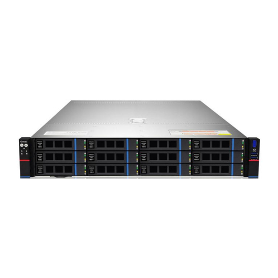
Summary of Contents for Gooxi SR201 2U
- Page 1 SR201 2U Rack Server User Manual Document Version: 02 Release Date: 16/Nov/2022 Shenzhen Gooxi Information Security Co., Ltd.
- Page 2 Gooxi does not provide guarantees for the results obtained from the use of this manual or the accuracy or reliability of any information obtained through this manual.
- Page 3 Foreword This manual is the product technical manual of Gooxi SR201 2U rackmount server, which mainly describes the appearance, structure, hardware installation and basic configuration of this product. This manual is for reference and research by professional technicians. This product should only be installed and maintained by experienced technicians.
- Page 4 Modification record Manual version Release date Remarks 2022/October/16 Initial release 2022/November/16 Optimized description...
-
Page 5: Table Of Contents
Contents 1 Product Description ..............................1 1.1 Product overview ............................1 1.2 Product structure ............................3 1.3 Logical structure ............................3 1.4 Product parameters ............................4 2 Hardware Description ............................... 6 2.1 Front panel ..............................6 2.1.1 Appearance ..............................6 2.1.2 LED and button ............................7 2.1.3 Interface .............................. -
Page 6: Product Description
The SR201 2U rackmount server is a new generation of 2U dual-socket rack server with a wide range of uses launched by Gooxi for the needs of the Internet, IDC (Internet Data Center), cloud computing, enterprise market, and telecom business applications. It is suitable... - Page 7 SR201-D25RE (Figure 1-3) 11-PCIe expansion rear window (Figure 1-4)
-
Page 8: Product Structure
Product structure The physical structure of the SR201 2U rack-mounted server is different due to different requirements, and the configuration will be different. Taking the SR201-D12RE model as an example, describe the components of the server, as shown in the figure below:... -
Page 9: Product Parameters
Motherboard logic block diagram (1-6) ·2 SP3 Sockets, supporting two AMD EPYC™ 7002 series processors; ·Single CPU supports 8 DDR4 channels, each channel supports 2 DIMMs, and the two CPUs support 32DIMM DDR4 memory; ·DDR4 type: DDR4 2400/2666/2933/3200MHz ECC-RDIMM/LRDIMM; ·There are 3 groups of PCIe RISER slots on the board, among which: 32 PCIE LANEs of RISER1 come from CPU0, 32 PCIE LANEs of RISER2 come from CPU1, 16 PCIE LANEs of RISER3 come from CPU1;... - Page 10 Chassis Gooxi 2U rackmount chassis ® Motherboard G1DLRO-B Support 2 AMD EPYC™ 7003/7002/7001 processors Type supports DDR4 RDIMM/LRDIMM; Frequency supports 2400/2666/2933/3200MHz; Memory Support single capacity of 8G/16GB/32GB/64GB/128GB/256GB, and the maximum memory capacity of the whole machine is 8TB. Front 8* 3.5 or 2.5 Front 12* 2.5 inch...
-
Page 11: Hardware Description
Hardware Description Front panel Appearance 2.1.1 8x3.5 inch hard drive configuration Figure (2-1) Name Name DVD drive USB3.0 interface VGA interface 3.5 inch hard drive Table (2-1) 12x3.5 inch hard drive configuration Figure (2-2) Name Name 3.5 inch hard drive USB3.0 interface VGA interface Table (2-2) -
Page 12: Led And Button
VGA interface Table (2-3) LED and button 2.1.2 Figure (2-4) LED/button LED/button Gooxi logo Hard drive LED Power switch button/LED System alarm LED UID button/LED Network port 1 connection status LED Reset server button Network port 2 connection status LED... -
Page 13: Interface
is located. Off: Indicates that the server is not located. UID button description: Short press this button to turn on/off the positioning light. Reset restart Press to restart the server server button Green flashing: The hard disk is operating HDD LED normally System warning LED. -
Page 14: Rear Panel
Table (2-5) Interface description Amount Name Type Description For connection to a display terminal, DB15 interface such as a monitor or KVM USB 3.0 For accessing USB devices interface Table (2-6) Rear panel Appearance 2.2.1 Appearance of the rear panel ... -
Page 15: Interface
transmission status LED connection status LED Network port data transmission Network port connection status LED status LED Restart button Power module LED Table (2-8) Description of power module LED LED/button Status description Green on: Indicates that the input and output are normal. -
Page 16: Processor
When configuring 1 processor, it needs to be installed in the CPU 0 position. Processors configured on the same server must have the same model. For specific optional purchasing system options, please consult Gooxi sales rep. The location of the processor is shown in the figure below: ... -
Page 17: Memory Compatibility Information
Figure (2-10) 2.4.2 Memory compatibility information The motherboard supports DDR4 RDIMM/LRDIMM server memory, and the memory frequency supports 2400/2666/2933/3200; Notice: The same server must use the same type of DDR4 memory, and all memory must run at the same speed, and the speed value is the lowest value of the following items: Memory speed supported by a particular CPU. -
Page 18: Storage
Note: 1: M1 can be inserted in any slot, C or D is recommended. 2: M1, M2 can be inserted in any slot, C or G is recommended. 3: M1 can be in any slot, M2 can be inserted in any other slot. 4: M1 ≠... - Page 19 Riser 1/2 module supports Front hard drive expansion of 4* 3.5 inch SAS hard drives need to 8x3.5 inch hard supports eight SAS/SATA hard drives. be equipped with SAS drive pass-thru 3.5 inch or 2.5 Riser 3/4 module supports pass-through card or configuration 1 inch SAS/SATA expansion of 4 2.5 -inch NVM e/...
-
Page 20: Hard Disk Serial Number
2.5.2 Hard disk serial number 8x3.5 inch hard drive configuration Figure (2-11) 12x3.5 inch hard drive configuration Figure (2-12) 25x2.5 inch hard drive configuration Figure (2-13) Hard disk status LED 2.5.3 Figure (2-14) Hard Disk Status LED Description ... -
Page 21: Power Supply
For power modules configured on the same server, the power module models must be the same; For specific optional purchasing system options, please consult Gooxi sales rep; The location of the power supply is shown in the figure below: ... -
Page 22: I/O Expansion
Figure (2-16) I/O expansion 2.8.1 PCIe slot distribution Figure (2-17) Riser 1 provides Slot0-2; Riser2 provides Slot3-5; Riser3 provides Slot6-7; Riser4 provides Slot8-9. Riser 1 is optional: two 3.5-inch hard disk modules/PCIE full-height expansion modules (choose 1 from 2): When selecting the PCIE expansion module, Slot0 can be connected to PCIe X8 or PCIe X16 devices, Slot1 can be connected to PCIe X8 devices, and Slot2 can be connected to PCIe X16 devices. -
Page 23: Pcie Slot Description
Riser 3 is optional: two 2.5-inch hard disk modules/PCIE half-height expansion modules (choose 1 from 2): When the PCIE expansion module is selected, Slot6 can be connected to PCIe X8 devices, and Slot7 can be connected to PCIe X16 devices. Note: (the position of this motherboard is one PCIe X16, and the PCIE expansion module is one X16, one x8). -
Page 24: Pcie Expansion Module
Full 3 PCIe X8 slots height, full length Half height, CPU 1 1 PCIe X16 slot half length PCIe x Riser 3 16 (3.0/4.0) Half height, CPU 1 2 PCIe X8 slots half length Half height, CPU 1 1 PCIe X16 slot half length 2*Silmline... - Page 25 slots. Figure (2-19) PCIe expansion module 3 Riser card for x16 to x8 (x16 slot)+x8 – Installed at Riser3, providing 1 PCIe X16 slot and 1 PCIe X8 slot. Figure (2-20) 3.5 inch hard disk module Figure (2-21) 2.5 inch hard disk module ...
-
Page 26: Pcba
PCBA 2.9.1 Motherboard G1DLRO-B motherboard diagram (2-23) Name 4U chassis fan control 4 pin interface Memory slot (corresponding to CPU 0) Memory slot (corresponding to CPU1) CPU0 CPU1 GPU Power 2*4 pin interfaces BP Power 2*4pin interfaces SFF8643 SATA interface USB3.0 interface BP I2C interface PCIe X8... - Page 27 IPMI RJ45 1Gb LAN RJ45 1Gb*2 DB-9 COM port USB3.0 OCP3.0 network card (optional) CPU1 PCIe X16 CPU1 PCIe X8 BP HDD LED Slimline PCIe X8 CPRS PSU GPU Power CPRS PSU RISER POW BP Power FP BIN LED PMBUS/BP5 I2C FP VGA FP USB3.0 Chassis Intrusion...
-
Page 28: Hard Disk Backplane
2.9.2 Hard disk backplane Front 8 × 3.5 inch hard disk backplane TOP surface Figure (2-24) Description Function 1. Support 12Gb/s SAS hard disk; 1, 2 SAS/SATA hard disk 2. Support 6Gb/s SATA hard disk; connector 3. Support SAS/SATA hard disk hot swap. - Page 29 12 x 3.5 inch backplane TOP surface Figure (2-26) Description Function 1. Support 12Gb/s SAS hard disk; SAS/SATA hard disk 2. Support 6Gb/s SATA hard disk; connector 3. Support SAS/SATA hard disk hot swap. Table (2-16) Bottom side Figure (2-27) Description Function Backplane power transmission...
- Page 30 25 x 2.5 inch backplane TOP surface Figure (2-28) Description Function 1. Support 12Gb/s SAS hard disk; SAS/SATA hard disk 2. Support 6Gb/s SATA hard disk; connector 3. Support SAS/SATA hard disk hot swap. Table (2-18) Bottom side Figure (2-29) Description Function Backplane power transmission...
- Page 31 2 × 2.5 rear hard disk backplane-1 TOP surface Figure (2-30) Description Function SAS/SATA hard disk 1. Support 12Gb/s SAS hard disk; connector 2. Support 6Gb/s SATA hard disk. Table (2-20) Bottom side Figure (2-31) Description Function 1, 5 7PIN SATA interface SATA disk signal cable interface Temperature sensor IC...
-
Page 32: Installation Notes
Installation Notes Chassis upper cover installation Step 1: Align the nails on the upper cover with the opening of the box and place it downwards; Step 2: Push forward to lock in the direction of the arrow. Figure (3-1) Mounting accessories 3.2.1 Install the CPU... - Page 33 Follow the instructions below to install the CPU: 1. In sequence (3 → 2 → 1), loosen the 3 fixing screws that secure the CPU cover. 2. Flip open the CPU cover. 3. Use the handle on the CPU tray to remove the CPU tray from the CPU rack. 4.
-
Page 34: Install Heat-Sink
Figure (3-4) 3.2.2 Install heat-sink Before starting to install the heat-sink, please read the following guidelines: Always turn off the computer and unplug the power cord from the electrical outlet before installing the heat sink to prevent damage to the hardware. Unplug all cables from electrical outlets. -
Page 35: Install Memory
Figure (3-5) 3.2.3 Install memory The 16 memory slots controlled by CPU 0 of the motherboard are: DIMMA1, A2, DIMMB1, B2, DIMM C1, C2, DIMM D1, D2, DIMM E1, E2, DIMM F1, F2, DIMM G1, G2 and DIMM H1, H2. The 16 memory slots controlled by CPU 1 are: DIMMA3, A4, DIMMB3, B4, DIMMC3, C4, DIMMD3, D4, DIMM E3, E4, DIMM F3, F4, DIMM G3, G4 and DIMM H3, H4. -
Page 36: Install The Server Rails
Figure (3-7) Figure (3-8) 3.2.4 Install the server rails Step 1: Prepare 2 slide rails and pull out the inner rail Figure (3-9) - Page 37 Figure (3-9 Step 2: Fasten the inner rails to the sides of the case Figure (3-10) Step 3: Install the outer rails on the cabinet brackets and secure the screws Figure (3-11) Note: When installing the guide rail, it is necessary to align with the U mark, and when it is installed in place with a snap, secure it with M5 screws.
- Page 38 Step 4: Align the chassis with the inner rails installed on the outer rails for installation Figure (3-12) Note: When you push the chassis forward, you will hear a snapping sound. If you can’t push it, you need to pull down the buckle of the inner rail to continue to push the chassis gently.
-
Page 39: Configuration Instructions
Configuration Instructions Initial configuration Power on 4.1.1 Before powering on, it is necessary to ensure that all configurations of the server are installed in accordance with the corresponding specifications and standards, and keep the server turned off but not unplugged from the power supply. - Page 40 Pic 4-1 AC Loss Control power-on control Status setting, the menu options are: Always off: power on directly Always on: You need to press the Power button to turn on the power Previous: Leave power state unchanged Log in to the iBMC management interface to perform remote power-on and power-off control.
-
Page 41: Initial Data
Figure 4-2 For detailed usage of BMC and BIOS, please refer to the corresponding user manual. Initial data 4.1.2 BMC default account: admin BMC default password: admin BMC default address: 192.168.x.x BIOS Default Password: None Configure BIOS 4.1.3 Press the <DEL>... -
Page 42: Configure Bmc
Figure 4-3 The Main interface contains the basic information of the BIOS system, such as the BIOS version number, CPU model, memory capacity, and the system time can be set. For detailed instructions, please refer to the "BIOS User Manual". ... - Page 43 Figure (4-4) Enter the account password to enter the home page, and you can set the BMC IP address on the management interface . On the left side of the interface, switch to "Settings Page" -> "Network Settings" -> "Network IP Settings". As shown below : Figure (4-5) When the server is powered on, make sure that the BMC dedicated management...
- Page 44 network port cable is properly connected. Use another device, make sure it is in the same LAN as the BMC management network, and enter the BMC IP address on the web page. Check the BMC IP address as follows: After the server is powered on, turn it on. Pay attention to the POST process when ...
- Page 45 Unspecified : Do not change BMC parameters (default) Static : BIOS static IP setting DynamicBmcDhcp : BMC runs DHCP to dynamically assign IP DynamicBmcNonDhcp : BMC runs Non-DHCP protocol to dynamically assign Configure IPV6 support Choose whether to support IPV6, the menu options are: ...
-
Page 46: Appendix
If the above operation does not solve the fault problem, it is recommended to replace the known correct monitor to confirm whether the original monitor is faulty If there are no problems, please contact Gooxi technical team to solve the problem Warning light on the front panel ... - Page 47 PING can be enabled by setting static or dynamic. If the WEB interface is invalid, please change to a new version of IE to connect. If the problem is still not resolved, please contact Gooxi technical team to solve it.
Need help?
Do you have a question about the SR201 2U and is the answer not in the manual?
Questions and answers