Table of Contents
Advertisement
Advertisement
Table of Contents

Related Manuals for Gooxi Purley Platform 1U


Summary of Contents for Gooxi Purley Platform 1U
- Page 1 Purley Platform 1U L-Shape Server Product Manual REV 1.0...
- Page 2 All trademarks used in this manual are the property of the trademark owner Intel, Pentium4, PentiumD, Xeon, Core and Celeron are registered trademarks of Intel Microsoft, MS-DOS, and Windows XP/NT/2000/2003 are registered trademarks of Microsoft AMD, Opteron is a registered trademark of AMD Netware is a registered trademark of Novell Award is a registered trademark of Award Software Inc IBM, VGA, PS/2, and OS/2 are registered trademarks of International Business Machines...
-
Page 3: Manual Framework
This manual is the product technical manual of Purley 1U dual cabinet server. It mainly introduces the technical characteristics, system architecture, installation method and basic operation of this product. Purley 1U dual cabinet server is divided into 1U4 disk and 1U10 disk. - Page 4 functions. Chapter 7 RAID Setup Instructions...
- Page 5 This chapter mainly describes how to set up RAID. Chapter 8 Rapid IPMI Deployment This chapter focuses on how to quickly deploy IPMI. Chapter 9 Jumper Setting Instructions This chapter focuses on the layout of the Purley 1U Dual cabinet Server Board and pin jumper setup instructions.
-
Page 6: Table Of Contents
Manual framework ..................2 Chapter 1 Safety Statement ................1 General safety issues ............... 1 Product toxic and hazardous substances or elements name and content identification table.............. 2 Warning notice ................5 Climate environment requirements ......... 5 Other important description ............. 6 Chapter II Product Introduction ................ - Page 7 5.2 1U4 bay 3.5-inch disk model motherboard to the backplane directly connected SATA model alignment instructions ....51 5.3 1U4 bay 3.5-inch disk SAS card to backplane model alignment 53 5.4 1U4 bay 3.5-inch disk type Raid card to backplane model alignment ....................
- Page 8 Chapter 10 Product Specifications ............... 283...
-
Page 9: Chapter 1 Safety Statement
Chapter 1 Safety Statement 1.1 General safety issues To prevent the risk of major personal and property damage, please be sure to follow the suggestions below. Do not open the cover of the system by yourself and it should be operated by a professionally trained service technician. -
Page 10: Product Toxic And Hazardous Substances Or Elements Name And Content Identification Table
Please keep the environment clean and avoid dust. The working temperature of the equipment is 10° C~35° C and the humidity is 35%~80%. Please promptly back up important data. Gooxi Technology Co., Ltd. is not responsible for data loss caused by any situation. - Page 11 Harmful Substance Hexava lent Polybromin Part Name cadmi chromiu ated lead biphenyls PBDE (Pb) (Hg) (Cd) (Cr VI) (PBB) (PBDE) Chassis/Baffl Mechanical components (fans, radiators, motors, etc.) Printed Circuit Components - PCA* Cable/wire/c onnector Hard disk drive Harmful Substance Hexava lent Polybromin Part Name...
- Page 12 Media reading/stora equipment (disc, etc.) Power Supply/Powe r Adapter power cable Pointing device (mouse, etc.) keyboard Complete cabinet / Rail Products ○ Indicates that the content of the toxic and hazardous substances in all homogeneous materials of the component is below the limit requirements specified in GB/T 26572-2011 "Limitations of Restricted Substances in Electrical and Electronic Products".
-
Page 13: Warning Notice
parts. 1.3 Warning notice This product meets the national CCC certification standards. 1.4 Climate environment requirements The optimal working temperature of the equipment is 10° C-35° C; the maximum indoor temperature of the equipment is 40° C. System battery 3 V CR2032 lithium battery. -
Page 14: Other Important Description
Choosing a suitable environment for the computer helps the computer run stably and can extend the life of the computer. Gooxi Technology Co., Ltd. reserves the right of final interpretation of the above terms and conditions 1.5 Other important description "If the device is marked with an identifier, it means that the device affixed with... -
Page 15: Chapter Ii Product Introduction
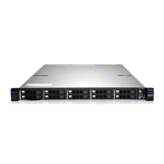
Chapter II Product Introduction 2.1 system introduction The Purley 1U dual cabinet server is a new generation of 1U dual-channel cabinet server with a wide range of uses that Taiyi uses for the Internet, IDC (Internet Data Center), cloud computing, enterprise market, and telecom service applications. Suitable for IT core business, cloud computing virtualization, high performance computing, distributed storage, big data processing, enterprise or telecom service applications and other complex workloads. - Page 16 Internal storage: 1 PCIe 3.0 x4 M.2 slot, 2 Mini SSD slots (SATA DOM) Front Bay: Up to 10 hot-swap 2.5-inch SAS/SATA (HDD/SSD) driver Or up to four 3.5-inch SAS/SATA (HDD/SSD) NVMe Support: Up to 10 hot-plug 2.5-inch NVMe/SAS/SATA (SSD/HDD) Platinum-class 550W, 800W, 1300W, 1600W hot swappable redundant power supply with power supply optional support for 240v and 338v DC...
- Page 17 2.2.1 system structure Purley 1U dual cabinet server with Intel Purley platform, with Intel Xeon SkyLake CPU; support 12 DDR4 Channel, 24 DDR4 slots; maximum support 3.0TB (with -M processor) memory capacity; The main board features are as follows: CPU uses Intel LGA3647-P0 SKY-LAKE processor;...
-
Page 18: System Model Specifications
2.3 System model specifications 1U4 bay 3.5 inch disk model (positive) <10>... - Page 19 (anti) product 1U4 (3.5" hard disk) name Supports 1 or 2 Intel SkyLake LGA3647 Xeon processors, supports Xeon series processor processors with OPA, (up to TDP 165W, optionally supports TDP 205W) Motherboard T1DM-E2 model chipset Intel® C620 Series Server-Specific Chipset Support DDR4 ECC RDIMMs/LRDIMMs server memory, memory frequency support 1866/2133/2400/2666MHz;...
- Page 20 1U10 disk position 2.5 inch disk model (positive) (anti) product name 1U10 (2.5" hard disk) Supports 1 or 2 Intel SkyLake LGA3647 Xeon processors, supports Xeon series processor processors with OPA, (up to TDP 165W, optionally supports TDP 205W) Motherboard T1DM-E2 model...
-
Page 21: System Components Introduction
3. In addition, it can also support 1* non-standard PCIEX8 SAS/RAID card slot+1* non-standard PCIEX8 card slot; hard disk Supports up to 10 3.5-inch SAS/SATA (HDD/SSD) M.2 SSD PCIE Gen3 X4 M.2 SSD(Support M.2 SSD length 80mm and 110mm) Two onboard 1GE, two optional 1GE/4 1GE/2 10GE/4 10GE/2 40GE network daughter cards Front port: VGA, 1 USB3.0, 1 Mini USB for LCD External port... - Page 22 VGA interface hard disk LCD dedicated interface Tag card USB 3.0 interface Front panel interface description name Types of Instructions VGA interface DB15 Used to connect display terminals such as monitors Or KVM. USB interface USB 3.0 Provides an out-of-port USB interface through which USB devices can be accessed.
- Page 23 System fault indicator Network port connection status indicator Fan failure indicator Power switch button/indicator Network port connection status indicator UID button/indicator 1U10 disk position 2.5 inch disk model System fault indicator Network port connection status indicator Fan failure indicator Power switch button/indicator Network port connection status indicator UID button/indicator...
- Page 24 Power switch Power indicator description: button/indicator Steady green: The device is powered on. Green (flashing): Indicates that the device is in the standby state. Green off: The device is not powered on. Power button description: Short press the button in the boot state, the OS shuts down normally.
- Page 25 Corresponds to two 1GE network ports on the motherboard. 2.4.2 Rear panel components Power Module 1 Extended network card (optional) Power Module 1 AC Interface VGA interface Power Module 2 Management network port Power Module 2 AC Interface USB 3.0 interface Rear extension module 2 GE electrical interface Post expansion module 1...
-
Page 26: State Description
interface devices can be accessed. note: When using an external USB device, make sure that the USB device is in good condition. Otherwise, the server may work abnormally. Server service network port. electrical BASE-T interface Power 1 or 2 You can choose the number of power supplies according to your Module AC actual needs, but you must ensure that the rated power of the Interface... - Page 27 supply is turned off due to power-on or in-position; the input is undervoltage. Green (4Hz/Flashing): Indicates the firmware upgrade process. Off: No AC power input is indicated. UID indicator The UID indicator is used to conveniently locate the server to be operated.
- Page 28 Dual-optical 10G network card: T82599L_2 Four-optical 10G network card: T710L-4 Dual-optical 40G network card: T710L-2X 2.4.3 Motherboard components All the models share the main board components. The interface description is as follows <20>...
- Page 29 HFI CPU1 SIDEBAND FP VGA CONN FP USB3.0 CONN HDD PWR3 GPU PWR2 (RISER1) RAID KEY LPC TPM MINI HD SATA PORT2 MINI HD SATA PORT0 MINI HD SATA PORT1 MEZZCONN 0 MCP XDP RISER1(PCIE3.0X24) RS232 M.2 CONN RISER2(PCIE3.0X24) NMI BUTTON DEDICATED LAN USB2 <21>...
- Page 30 USB1 Ethernet 2 Ethernet 1 ID BUTTON RISER3(PCIE3.0X16) HDD PWR2 SATA DOM/DVD1 Power Module 2 Connector (J2) SATA DOM/DVD2 USB3.0 CONN LED CONN2 HDD PWR1 GPU PWR 1(RISER2) Power Module 1 Connector (J1) BP PWR3 BP PWR1 CD_PWR1 LED CONN1 BP PWR2 DOM_PWR2 DOM_PWR1...
- Page 31 Bottom surface ITEM Description Function Location MINI SAS HD High Speed For 12G/b SAS or 6G/b SATA signal transmission. Connector Backplane power transfer connector Power connector for transmission of 12V power. 1U10 2.5” backplane as shown Top surface Device description Functional description Bit number berin...
- Page 32 Numb Device description Functional description Bit number ering MINI SAS HD High Speed Used for transmission of 12G/b SAS or 6G/b J2,J3,J4 SATA signals. Connector Backplane power transfer connector for Power connector transmission of 12V power. 2.4.5 DIMM slot location The motherboard uses Intel Purley platform with Intel Xeon SkyLake CPU, supports 12 DDR4 channels, 24 DDR4 slots, supports DDR4 ECC RDIMMs/LRDIMMs...
- Page 33 1U10 disk position 2.5 inch disk model 2.4.7 Hard disk indicator Hard disk status Green LED Yellow LED Hard disk is not in place Hard disk in place, but no data activity Hard disk in place, and normal activities The flash frequency of the hard disk itself Hard disk failure...
-
Page 34: Chapter 3 Installing System Components
2.4.9 System fan The server supports variable fan speeds. In general, the fan rotates at the lowest speed. If the server temperature increases, the fan will increase the speed to cool down. Chapter 3 Installing System Components 3.1 CPU installation Install the processor: Step 1: CPU installation 1-1. - Page 35 Step 2: Install the CPU on the heat sink to ensure that the surface of the CPU and heat sink is clean, free of oil and foreign matter. (As shown below) 2-1. Apply approximately 0.4 ml volume of thermal grease to the CPU and apply evenly. 2-2.
-
Page 36: Radiator Installation
3.2 Radiator installation installation steps: 1. Remove the processor blanking plate (shown below) 2. Align the heat sink with the heat sink retention studs on the CPU base, and tighten the heat sink retention screws as indicated. (As shown below) Note: The pins on the motherboard are extremely fragile and easily damaged. - Page 37 DIMMG1, G2 and DIMMH1, H2, should pay attention to the memory of the gap with the DIMM slot gap, each DIMM module vertically snap into place to prevent the incorrect installation. <29>...
-
Page 38: Hard Disk Installation
3.4 Hard disk installation Installing a 3.5-inch hard disk 1-1. Put the hard disk in the tray 1-2. There are 4 countersunk screws on the left and right sides to lock the hard disk (the screw head must not protrude from the slide surface on both sides of the tray) <30>... - Page 39 Installing a 2.5-inch hard disk 1-1. Put the hard disk in the tray 2-2. The bottom four countersunk screws lock the hard disk (screw head protrudes from the underside of the tray) <31>...
-
Page 40: Front Hard Disk Backplane Installation
Hard disk tray assembly installed in the chassis 1-1. With the hard disk wrench open, push it into the chassis 1-2. When the hard disk gold finger touches the backplane device, turn the wrench in the direction of the arrow. 1-3. - Page 41 1-2. After the hard disk backplane is pushed fully into place, press down on the backplane until the gourd nails and holes on both sides are in place. 1-3. Flip the left and right fasteners on the hard disk backplane. <33>...
-
Page 42: Ssd Installation
3.6 M.2 SSD installation Step 1: Install the positioning studs according to the length of the M.2 card to be installed. Step 2: Install the M.2 card 2-1. Insert the M.2 card connector end into the motherboard connector as shown. 2-2. -
Page 43: Pci-E Module Installation
Step 3: Install the M.2 card fixing screws. 3.7 PCI-E module installation Steps: Rear window PCIE assembly, placed vertically downwards - aligned with the PCIE slot, aligned with the locating hole, placed flush with the rear window. <35>... -
Page 44: Network Module Installation
3.8 Network module installation For server systems, a total of five dedicated expansion network cards have been developed. Each type of network card has a dedicated blank for installation. <36>... - Page 45 Step 1. Install the back-end expansion network card 1-1. Schematically obliquely downwards 1-2. Align the expansion card window and push it in the direction of the arrow 1-3. After retreating, lay flat <37>...
- Page 46 Step 2. Fix the back-end expansion network card 2-1. Turn the insulation pad up and down in the direction of the arrow to leak out the screw holes 2-2. Locking 3 Flathead Screws 2-3. After the screws are locked, reset and smooth the insulation pad flipped by the 2-1 operation.
-
Page 47: Power Module Installation
3.9 Power module installation Step: The power supply is pushed in the direction of the arrow, and the shrapnel wrench on the right emits a sound, indicating that it is in place; <39>... -
Page 48: Pci-E Expansion Card Installation
3.10 PCI-E expansion card installation Step: Install the PCIE card 1-1. Load the PCIE card in the direction indicated in the figure 1-2. Rotate the PCIE card lock 1-3. Lock the PCIE card lock according to the arrow scheme <40>... -
Page 49: Fan Module Installation
3.11 Fan module installation Steps: Place the fan module vertically downwards by pressing the arrow (Caution that the fan module faces) <41>... -
Page 50: Windshield Installation
3.12 Windshield installation Step: The wind shield module is aligned with the hanging points on the left and right sides and is placed vertically downwards - the height is lower than the height of the box <42>... -
Page 51: Optical Drive Installation
3.13 Optical drive installation Step: Install the optical drive 1-1. Install the optical drive fasteners in the direction of the arrow and tighten the pan head screws 1-2. Align the opening of the optical drive on the chassis and push the optical drive in the direction of the arrow until it locks automatically. -
Page 52: Chassis Cover Installation
3.14 Chassis cover installation Step: Install the chassis cover 1-1. Top Peg Placement Aligns the open position of the cabinet and places it downwards 1-2. Rotate the upper cover lock in the direction of the arrow to lock it into place <44>... - Page 53 <45>...
-
Page 54: Chapter Iv System Cabinet Installation
Chapter IV System cabinet Installation Step 1. After removing the inner rail from the rail, push the middle rail into the rail 1-1. Pull out the inner rail from the guide rail, and you can hear a click and stop 1-2. - Page 55 2-1. Align the positioning holes of the inner rail with the four hanging screws on the side of the chassis, and install the inner rail to the chassis according to the diagram. After the installation is completed, you can hear a click and you need to ensure that it is in place.
- Page 56 complete the installation of the rear rail. 3-3. Push the front end of the rail in accordance with the arrow to align the cabinet hole and insert the rail into the cabinet. 3-4. After installing the rail into the front of the cabinet and hearing a beep, step 3 is completed.
- Page 57 Step 4. Install the server to cabinet. 4-1. Withdraw the two side rails installed in the cabinet so that you can hear a click and stop. 4-2. Raise the server and align the rail inner rails with the center rail, and push the server into the cabinet in the direction of the arrow to ensure that the inner rails fit smoothly into the center rail.
- Page 58 <50>...
-
Page 59: Chapter 5 Cable Connection Instructions
Chapter 5 Cable Connection Instructions 5.1 1U4 model front panel connection Numberi Cable description Light board to main board signal line Front USB3.0 signal cable to the motherboard Front VGA to motherboard signal line Intrusion Detection Switch to Motherboard Signal Line 5.2 1U4 bay 3.5-inch disk model motherboard to the backplane directly connected SATA model alignment instructions ... - Page 60 Numberi Cable description Power cable from the front hard disk backplane to the mainboard SAS cable from front hard disk backplane PORT 0 to mainboard PORT 0 Board-to-optical drive alignment <52>...
-
Page 61: 1U4 Bay 3.5-Inch Disk Sas Card To Backplane Model Alignment
Numberi Cable description Optical drive to motherboard power cable Optical drive to motherboard SATA signal cable 5.3 1U4 bay 3.5-inch disk SAS card to backplane model alignment <53>... - Page 62 Numberi Cable description Power cable from the front hard disk backplane to the mainboard SAS line from the front hard disk backplane PORT 0 to SAS card PORT 0 <54>...
-
Page 63: 1U4 Bay 3.5-Inch Disk Type Raid Card To Backplane Model Alignment
5.4 1U4 bay 3.5-inch disk type Raid card to backplane model alignment Numberi Cable description Super capacitor to Raid card connector SAS line from the front hard disk backplane PORT 0 to the Raid card PORT 0 (For the power cable of the front hard disk backplane to the main board, refer to the 1U4 bay 3.5-inch disk SAS card to the rear panel model. -
Page 64: 1U10 Tray Type Front Panel Connection
5.5 1U10 tray type front panel connection Numberi Cable description Light board to main board signal line Front USB3.0 signal cable to the motherboard Front VGA to motherboard signal line Intrusion Detection Switch to Motherboard Signal Line <56>... -
Page 65: 1U10 Bay Main Board To Backplane Direct Connection Sata Model Alignment Description
5.6 1U10 bay main board to backplane direct connection SATA model alignment description Numberi Cable description Motherboard to front backplane power cable SAS line from mainboard PORT 0 to front panel PORT 0 Board PORT 1 to the SAS line on front panel PORT 1 Motherboard PORT 2 to SAS cable on front panel PORT 2 <57>... -
Page 66: 1U10 Disk Sas Card To Backplane Direct Connection
5.7 1U10 disk SAS card to backplane direct connection Numberi Cable description Motherboard to front backplane power cable SAS line from the front hard disk backplane PORT 0 to SAS card PORT 0 SAS line from the front hard disk backplane PORT 1 to the SAS card PORT 1 SAS cable from front hard disk backplane PORT 2 to SAS card 2 PORT 0... -
Page 67: 1U10 Tray Raid Card To The Back Of The Direct Connection Model Description
5.8 1U10 tray Raid card to the back of the direct connection model description Numberi Cable description Super capacitor to Raid card 1 connector Super capacitor to Raid card 2 connection line SAS line from front hard disk backplane PORT 0 to Raid card 1 PORT 0 Front SAS hard disk backplane PORT 1 to Raid card 1 PORT 1 SAS cable... -
Page 68: 1U10 Disk Raid Card + Sas Card To The Backplane Direct Connection
PORT 0 (The power cable from the front hard disk backplane to the main board refers to the 1U10 bay SAS card to the backplane model. 5.9 1U10 disk Raid card + SAS card to the backplane direct connection <60>... - Page 69 Numberi Cable description Super capacitor to Raid card connector SAS line from the front hard disk backplane PORT 0 to the Raid card PORT 0 Front SATA hard disk backplane PORT 1 to Raid card SAS 1 SAS cable SAS cable from PORT 2 on the front hard disk backplane to PORT 0 on the SAS card (The power cable from the front hard disk backplane to the main board refers to the...
-
Page 70: 1U10 Tray Raid Card + Motherboard To Backplane Direct Connection
5.10 1U10 tray Raid card + motherboard to backplane direct connection (This wiring diagram is due to the perspective problem. The 8643 connector of the 1U rear view RAID card overlaps with the SATA connector of the mainboard. Therefore, the wiring diagram uses the middle RAID card to indicate the priority. -
Page 71: Raid Card
RAID card. Numberi Cable description Super capacitor to Raid card connector SAS line from the front hard disk backplane PORT 0 to the Raid card PORT 0 Front SATA hard disk backplane PORT 1 to Raid card SAS 1 SAS cable SAS cable from the front hard disk backplane PORT 2 to the motherboard card PORT 0... -
Page 72: Chapter 6 Bios Parameter Setting Instructions
Chapter 6 BIOS Parameter Setting Instructions 6.1 Enter BIOS Setup interface Steps: 1. Power on the server board and connect the keyboard; 2. During the POST process, observe the prompt on the lower left side of the Logo screen to enter the BIOS Setup screen, "Press <DEL> or <ESC> to enter setup, <F7>... - Page 73 Server Board Information Project Version: Displays the BIOS version of the board. Build Date and Time: Displays the compilation date and time of the board BIOS. Manufacturer: Display the board manufacturer. Product Name: Displays the name of the board. Platform Information Processor: CPU model information.
- Page 74 CPU1 specific model information. Processor 2 Version CPU2 specific model information. PCH: PCH model and version information RC Revision: Displays RC code version information. Memory Information: Total Memory: Displays the total system memory capacity. System Language: Menu language. System Date: Displays and sets the current system date.
- Page 75 6.2.3 Advanced menu description The Advanced interface contains advanced configuration items of the BIOS system. ●Intel® Virtual RAID on CPU Display and set the virtual RAID information under Intel CPU. ●ALL CPU Information Current system CPU information. ●Trusted Computing Trusted execution module configuration. ●ACPI Settings ACPI configuration.
- Page 76 ●SIO Configuration SuperIO configuration. ●Option ROM Dispatch Policy OptionROM performs policy configuration. ●PCI Subsystem Settings PCI subsystem settings. ●Network Stack Configuration Network stack configuration. ●CSM Configuration CSM module configuration. ●NVMe Configuration NVMe configuration. ●USB Configuration USB configuration. <68>...
- Page 77 6.2.4 Intel® Virtual RAID on CPU Displays and sets the hard disk information and RAID configuration of the NVMe interface. For configuring different brands of NVMe hard disk RAID, you need to insert Key on the motherboard. <69>...
- Page 78 <70>...
- Page 79 <71>...
- Page 80 6.2.5 ALL CPU Information Display the system CPU model, version and other details. <72>...
- Page 81 6.2.6 Trusted Computing Display and set the TCM/TPM module information. There are differences in the settings of different module options. The user can set it according to the Setup Help. The administrator password is not set and this menu cannot be edited. <73>...
- Page 82 6.2.7 ACPI Settings Enable ACPI Auto Configuration ACPI automatic control switch. The menu options are: ● Disabled: Disables automatic ACPI configuration and whether the hibernation status is controlled by the user. ● Enabled: Enables automatic ACPI configuration. The system automatically configures whether it supports sleep.
- Page 83 ●Disabled: Off Default: Enabled 6.2.8 Serial Port Console Redirection Console Redirection The console redirection function switch redirects information output from the console (such as a graphics card) to the monitor to the serial port. ● Disabled: Disables the redirection function. ●...
- Page 84 6.2.9 Console Redirection Settings Terminal Type This option allows you to select the type of emulation, which must match the mode selected in the terminal program. The menu options are: ●VT100 ●VT100+ ●VT-UTF8 ●ANSI Default value: VT100 Bits per second Serial port redirection rate, in the range of 9600 to 115200 Default: 115200 <76>...
- Page 85 Data Bits Serial port redirection data bit length, the menu options are: ●8 ●7 Default: 8 Parity Serial port redirection check switch, the menu options are: ●None: no check Even: even parity ● Odd: odd parity ●Mark: The check digit is always 1 ●Space: Checksum is always 0 Default: None Mark and Space checks are not allowed to detect errors.
- Page 86 ●Disabled: Off Default: Disabled 6.2.10 SIO Configuration <78>...
- Page 87 Press [*Active*] Serial Port to enter submenu Use This Device Serial function control switch, the menu options are: ●Enabled: On ●Disabled: Off Default: Enabled Possible: Serial port resource control, automatically set resources, or set IO resources and IRQ resources, the menu options are: ●Use Automatic Settings: ●IO=3F8h;...
- Page 88 Default: Use Automatic Settings If the user does not have special needs, it is recommended to use the default configuration. 6.2.11 Option ROM Dispatch Policy Displays the current Option ROM operating strategy, UEFI mode, and Legacy mode for network, storage, display, and other devices. Restore if Failure Start the failure recovery function.
- Page 89 ●Disabled: Off Default: Disabled Primary Video Ignore The top priority display device ignores the setting function. When the user turns off the most preferred display device OptionROM, the system will ignore this setting and will restore Enabled. The menu options are: ●Enabled: On ●Disabled: Off Default: Enabled...
- Page 90 6.2.12 PCI Subsystem Settings Above 4G Decoding More than 4G memory space resource decoding control switch, the menu options are: ●Enabled: On ●Disabled: Off Default: Enabled SR-IOV Support SR-IOV technology enable switch, the menu options are: ●Enabled: On ●Disabled: Off Default: Enabled <82>...
- Page 91 6.2.13 Network Stack Configuration Network Stack Network stack control switch, menu options are: ●Enabled: On ●Disabled: Off Default: Enabled Ipv4 PXE Support Ipv4 UEFI PXE function control switch, the menu options are: ●Enabled: On ●Disabled: Off Default: Enabled <83>...
- Page 92 Ipv4 HTTP Support Ipv4 HTTP function control switch, the menu options are: ●Enabled: On ●Disabled: Off Default: Disabled Ipv6 PXE Support Ipv6 UEFI PXE function control switch, the menu options are: ●Enabled: On ●Disabled: Off Default: Disabled Ipv6 HTTP Support Ipv6 HTTP function control switch, the menu options are: ●Enabled: On ●Disabled: Off...
- Page 93 6.2.14 CSM Configuration CSM Support The CSM module supports control switches. The menu options are: ●Enabled: On ●Disabled: Off Default: Enabled Boot option filter Start the option class control switch. The menu options are: ● UEFI and Legacy: UEFI and Legacy startup items ●...
- Page 94 Option ROM Policy The device Option ROM runs a policy control switch. The menu options are: ● UEFI: UEFI mode ● Legacy: Legacy mode Default: UEFI After this option is selected, network, storage, display, and other devices will follow this selection. 6.2.15 NVMe Configuration <86>...
- Page 95 Displays the details of the NVMe hard disk. You need to set the U.2 Device NVMe Mode to Non-VMD Mode and Storage to Legacy. <87>...
- Page 96 6.2.16 USB Configuration Displays USB controller and USB device information. Legacy USB Support Legacy environment USB support control switch, the menu options are: ●Enabled: On ●Disabled: Off Default: Enabled XHCI Hand-off Change the XHCI control switch. This feature is effective for operating systems that do not support changing XHCI control.
- Page 97 ●Enabled: On ●Disabled: Off Default: Enabled USB Mass Storage Driver Support USB storage device driver control switch, the menu options are: ●Enabled: On ●Disabled: Off Default: Enabled 6.2.17 Platform menu ●PCH Configuration PCH configuration. <89>...
- Page 98 ●Server ME Configuration Server ME configuration. Active Video Display device control switch, menu options are: ●Onboard Device: On-board display device ●Offboard Device: External display device Default: Onboard Device 6.2.18 PCH Configuration ●PCH SATA Configuration PCH SATA device configuration. ●Server sSATA Configuration <90>...
- Page 99 PCH sSATA device configuration. Restore AC Power Loss AC power off and then power on the system status control switch. The menu options are: ●PowerOn: boot ●PowerOff: Shutdown ●Last State: Holds the state before power-off Default: Last State 6.2.19 PCH SATA Configuration SATA Controller The SATA controller opens and closes the control switch.
- Page 100 ●Enable: On ●Disable: Close Default: Enable Configure SATA as SATA controller operating mode selector switch, the menu options are: ● AHCI: AHCI mode ● RAID: RAID mode Default value: AHCI SATA Port X Displays the SATA port 0~7 device information, and dynamically obtains the status of the hard disk in place.
- Page 101 Alternate Device ID on RAID The RAID controller device ID replaces the control switch. On is to replace the device ID with the AHCI mode. The menu options are: ●Enable: On ●Disable: Close Default: Disable The RAID mode is visible. Load EFI Driver for RAID RAID EFI drive control switch, which will load RAID EFI driver when open, the menu options are:...
- Page 102 6.2.20 SATA Mode options SATA HDD Unlock The SATA hard disk password under the operating system unlocks the control switch. The menu options are: ●Enable: On ●Disable: Close Default: Enable RAID X RAID mode control switch, the menu options are: ●Enable: On ●Disable: Close Default: Enable...
- Page 103 The RAID mode is visible. RAID OROM prompt delay RAID OROM run prompt time, user can input, default 2 seconds. The RAID mode is visible. 6.2.21 Server ME Configuration Displays information such as the version, status, and function of the server <95>...
- Page 104 6.2.22 Socket menu ●Processor Configuration Processor configuration ●UPI General Configuration UPI configuration ●Memory Configuration Memory configuration ●IIO Configuration IIO configuration ●Advanced Power Management Configuration Advanced power management configuration <96>...
- Page 105 6.2.23 Processor Configuration menu Displays the processor model number, ID number, frequency, Microcode version, L1/L2/L3 cache size, processor specific model, and other information. Hyper-Threading [ALL] Hyper-Threading Control Switch, this option enables or disables the Intel Processor Hyper-Threading feature. With this feature enabled, each physical processor core is equivalent to two logical processor cores;...
- Page 106 Default: Enable Execute Disable Bit Hardware anti-virus technology switch, this option protects the system from malicious code and viruses. When the memory does not contain executable code, this memory interval should be set to an unexecutable property. Some viruses try to insert and execute code from an unexecutable memory location.
- Page 107 Enable SMX Security Mode Extended Capability Switch. With this option enabled, SMX will create a secure environment for the system software to support platform end users to make trust decisions. ●Enable: On ●Disable: Close Default: Disable Hardware Prefetcher Hardware prefetching means that before the CPU processes an instruction or data, it prefetches the instruction or data from the memory into the L2 cache, thereby reducing the memory read time and helping eliminate potential bottlenecks, thereby improving system performance.
- Page 108 menu options are: ●Enable: On ●Disable: Close Default: Enable DCU IP Prefetcher DCU IP prefetch feature switch. This option enables (default) or deactivates the Data Cache Unit (DCU) IP prefetcher, which has an impact on performance depending on the application running on the server. The menu options are: ●Enable: On ●Disable: Close...
- Page 109 6.2.24 Per-Socket Configuration menu <101>...
- Page 110 The user can enter BitMap to mask some of the processor cores, not exceeding the processor's maximum number of cores, leaving at least one core activated. The default value is 0 and all cores are activated. <102>...
- Page 111 6.2.25 UPI General Configuration menu ●UPI Status UPI link status information display Link Speed Mode Link speed mode settings, menu options are: ●Fast: quick mode ●Slow: slow mode Default: Fast Link Frequency Select Link frequency selection configuration, set the UPI link frequency to a lower speed, running at a lower frequency can reduce power consumption, but at the same time affect system performance.
- Page 112 configured when there are two CPUs. The menu options are: ●Auto: automatic setting ● 9.6GT/s: 9.6 Gigabits per second ● 10.4 GT/s: 10.4 Gigabits per second ●Use Per Link Setting Default: Auto Display system CPU number, IIO quantity, current UPI speed mode, current UPI link speed information.
- Page 113 6.2.26 Memory Configuration menu ●Memory Topology menu Display memory information ●Memory RAS Configuration menu Memory RAS configuration Enforce POR Execution parameter design limits the control switch, Auto and POR to enable this function, memory frequency and voltage will be limited by platform parameter design.
- Page 114 Memory Frequency Memory speed configuration, menu options are: ●Auto ●1866 ●2133 ●2400 ●2666 Default: Auto Attempt Fast Boot Set quick hot start, the menu options are: ●Auto: Automatic ●Enable: On ●Disable: Close Default: Disable Attempt Fast Cold Boot Set quick cold start, the menu options are: ●Auto: Automatic ●Enable: On ●Disable: Close...
- Page 115 6.2.27 Memory Topology menu Displays the current system memory details. <107>...
- Page 116 6.2.28 Memory RAS Configuration Menu Static Virtual Lockstep Mode Static virtual Lockestep mode, the menu options are: ●Enable: On ●Disable: Close Default: Disable Mirror mode Memory mirroring mode, the menu options are: ● Disable: Disables the memory mirroring mode ●Mirror Mode 1LM ●Mirror Mode 2LM Default: Disable <108>...
- Page 117 Mirror TAD0 Low address mirroring function, the menu options are: ●Disable: Close ●Enable: On Default: Disable Enable Partial Mirror Partial mirroring function, the menu options are: ● Disable: Disables part of the memory mirroring mode ●Partial Mirror Mode 1LM ●Partial Mirror Mode 2LM Default: Disable Patrol Scrub The memory patrol function is corrected as soon as it finds correctable...
- Page 118 6.2.29 IIO Configuration menu ●Socket1 Configuration menu CPU1 configuration menu ● Socket2 Configuration menu CPU2 configuration menu ●Intel® VT for Directed I/O (VT-d) menu Intel Virtualization Configuration Menu ●Intel® VMD technology menu Intel VMD Technology Configuration Menu EV DFX Features <110>...
- Page 119 EV DFX feature switch. The menu option is ●Enable: On ●Disable: Close Default: Disable 6.2.30 Socket Configuration menu All PCIE device configuration menus are displayed. This is a dynamic display interface. The display varies according to the motherboard access interface. <111>...
- Page 120 6.2.31 Intel® VT for Directed I/O (VT-d) menu Intel® VT for Directed I/O (VT-d) VT-d function control switch, the menu options are: ●Disable: Close ●Enable: On Default: Disable Interrupt Remapping After the VT_D interrupt remap switch is turned on, the hypervisor and operating system that supports this option can use Intel Virtualization Technology to provide interrupt remapping hardware capabilities for directed I/O.
- Page 121 options are: ●Disable: Close ●Enable: On Default: Enable Visible when VT-d is Enable. 6.2.32 Intel® VMD technology menu U.2 Device NVMe Mode U.2 interface NVMe device control mode switch. Select VMD Mode. The U.2 interface NVMe device attached to the CPU is managed using the VMD function.
- Page 122 Default: VMD Mode When changing from VMD Mode to Non-VMD Mode, hot restart operation is not supported. You can choose to save, shut down, and then boot. 6.2.33 Advanced Power Management Configuration menu ●CPU P State Control menu CPU P status control menu ●...
- Page 123 6.2.34 CPU P State Control menu Uncore Freq Scaling(UFS) Uncore Frequency Scaling function switch, the menu options are: ●Enable: On ●Disable: Close Default: Enable SpeedStep (Pstates) Intelligent Frequency Modulation (EIST), the menu options are: ●Enable: On ●Disable: Close Default: Enable <115>...
- Page 124 Boot performance mode Boot Performance mode selection, the menu options are: ● Max Performance: Set Boot Performance to Maximum Performance Mode ● Max Efficient: Sets Boot Performance to the maximum economic mode Set by Intel Node Manager: Set Boot Performance to be controlled by the Default: Max Performance SpeedStep select Disable, not editable.
- Page 125 Non-Turbo maximum frequency, input range 0~100, default value is 23. Cannot be edited when the "CPU Flex Ratio Override" option is Disabled. 6.2.35 CPU C State Control menu Autonomous Core C-state ●Enable: On ●Disable: Close Default: Disable CPU C6 report C6 status control switch, the menu options are: <117>...
- Page 126 ●Auto: automatic setting ●Enable: On ●Disable: Close Default: Auto This item cannot be edited when Autonomous Core C-state selects Enable. Enhanced Halt State (C1E) C1E status control switch, the menu options are: ●Enable: On ●Disable: Close Default: Enable This item cannot be edited when Autonomous Core C-state selects Enable.
- Page 127 6.2.36 Package C State Control menu Package C State Package C State limit options, menu options are: ●Auto: Automatic ● C0/C1 state: Set to C0/C1 state ● C2 state: set to C2 state ● C6 (non Retention) state: set to C6 (non-residual) state ●...
- Page 128 6.2.37 CPU - Advanced PM Tuning Menu Power Performance Tuning Power performance tuning control switch, the menu options are: ● OS Controls EPB: Operating System Control Performance Tuning ● BIOS Controls EPB: BIOS control performance adjustment Default: OS Controls EPB ENERGY_PERF_BIAS_CFG mode Performance adjustment configuration mode, the menu options are: ●Performance: performance first...
- Page 129 Default value: Balanced Performance Power Performance Tuning is set to OS Controls EPB. This item is not editable. 6.2.38 Server Mgmt menu Displays the BMC self-test status, device ID, device version, BMC software version, and IPMI specification version. ● System Event Log menu System Event Record Control Menu ●BMC network configuration menu BMC network configuration menu...
- Page 130 View system event record control menu BMC Warm Reset Select this option and press Enter on the keyboard. Select Yes in the popup window to send a restart BMC command to the BMC. 6.2.39 System Event Log menu SEL Components Start-up process system event logging function control switch, menu options: ●Enabled: On...
- Page 131 Clear system event record control switch, menu options: ●No: Do not clear ●Yes, On next reset: next restart reset once ●Yes, On every reset: Clear once every reboot Default value: No When SEL is Full When the system event record memory is full, operate the control switch, menu options: ●Do Nothing: Do not operate ●Erase Immediately: Clear Now...
- Page 132 6.2.40 BMC network configuration menu BMC Dedicated Management Channel Displays the network parameter information of the IPMI private network port, the current IP configuration mode, BMC IP, subnet mask, MAC address, and route IP. BMC Sharelink Management Channel Displays the network parameter information of the system shared network port, the current IP configuration mode, BMC IP, subnet mask, MAC address, and route IP address.
- Page 133 ●Unspecified: Does not change BMC parameters ● Static: BIOS static IP settings ● DynamicBmcDhcp: BMC runs DHCP to dynamically allocate IP ● DynamicBmcNonDhcp: The BMC runs the Non-DHCP protocol to dynamically allocate IP addresses Default: Unspecified After changing from Unspecified to other parameters, the option will restore the Unspecified value after the restart execution is executed.
- Page 134 6.2.42 Security menu Administrator Password Administrator password setting options, select this option to edit the administrator password. User Password User password setting options, select this option to edit the user password. Admin Pwd Status The administrator password status is displayed with the password "INSTALLED"...
- Page 135 HDD Security Configuration: The hard disk list is displayed dynamically. The hard disk connected to the SATA and sSATA controllers is displayed here. Enter the hard disk interface to set the hard disk password. No hard disk connection is not displayed. 6.2.43 Boot menu Setup Prompt Timeout...
- Page 136 ●off: off Default: on Logo Display Select the Logo mode. When this option is enabled, the logo mode is output. When it is closed, the text mode is output. The menu options are: ●Enabled: On ●Disabled: Off Default: Enabled Boot Option Priorities A list of startup options.
- Page 137 6.2.44 Save & Exit menu Discard Changes and Exit Give up the change and exit the Setup screen. Save Changes and Reset Save changes and restart the system. Save Changes Save changes. Discard Changes Give up change. Restore Defaults Load the BIOS factory defaults. Boot Override <129>...
-
Page 138: User Operation Reminder
A list of startup options from which you can choose startup options. 6.3 User operation reminder 1. With options, when the user needs to operate, understand the operating specification in detail. 2. When operating options, please refer to the operating manual and BIOS Setup interface options to understand the meaning of the options. - Page 139 Move to the PlatForm page -> PCH Configuration -> PCH Sata Configuration -> Configure SATA as. Configure the SATA RAID mode, as shown in Figure 1-1. Figure 1-1 Configure SATA to RAID mode: Ensure that the storage and video in the CSM Configuration are in UEFI mode, as shown in Figure 1-2 ...
- Page 140 Restart the server and enter the BIOS Setup interface. Move to the Advance page. You will see the intel(R) RSTe SATA Controller. Press enter to enter the configuration RAID, as shown in Figure 1-3 Figure 1-3 Intel RSTe SATA Controller <132>...
- Page 141 Create a RAID Select Create RAID Volume and press enter. Picture 1-4 Figure 1-4 Creating a RAID <133>...
- Page 142 Change the name of the created raid, taking care not to include special characters. Picture 1-5 Figure 1-5 Creating a RAID Name <134>...
- Page 143 RAID Level: Select the raid level of the group, as shown in Figure 1-6 Figure 1-6 Selecting a RAID Level for a Group <135>...
- Page 144 Select Disks: Press the space bar to select the disks that need to participate in the group RAID. As shown in Figure 1-7 Figure 1-7 Selecting a RAID Disk <136>...
- Page 145 Select Create Volume and press Enter to group raid. The related parameters are described in Table 1-1: paramete Instructions Name The name of the RAID. RAID level, which determines logical disk performance, fault tolerance, and RAID Level capacity. Select the member disk that makes up RAID. The available disk is Select displayed below the Select Disks column.
- Page 146 As shown in Figure 1-8, select the disk to be configured as a hot spare and press Enter. Figure 1-8 Selecting Disks to Configure as Hot Spare Disks Go to the screen shown in Figure 1-9. Select Mark as Spare and press Enter. ...
- Page 147 Enter the page shown in Figure 1-10. Select Yes and press Enter to complete the hot spare disk configuration. Figure 1-10 Checking the configuration of the hot spare disk <139>...
- Page 148 Remove RAID Enter the RSTe configuration interface. As shown in Figure 1-11, select the RAID to be deleted in the RAID Volumes directory and press Enter. Figure 1-11 Selecting RAID to be deleted <140>...
- Page 149 Enter the RAID information interface shown in Figure 1-12. Select Delete and press Enter to delete the RAID. Figure 1-12 RAID information interface <141>...
- Page 150 7.1.2 Legacy boot mode to configure RAID Set the RSTe mode of operation Enter the BIOS Setup interface. Move to the PlatForm page -->PCH Configuration-->PCH Sata Configuration Figure 3-16 PCH SATA Configuration Interface <142>...
- Page 151 The /RSTe onboard software RAID has two controllers, SATA and sSATA, which manage the disks connected to the two interfaces of the RAID card. The SATA controller supports up to eight disks, and the sSATA controller supports up to six disks. Enter the page shown in Figure 3-18, select the Configure SATA As item, and press Enter to select the working mode of the RSTe onboard software RAID.
- Page 152 Enter RSTe configuration interface Power on or restart the server. After the BIOS starts, the interface shown in Figure 1-14 appears. Press Ctrl+I. Figure 1-14 BIOS startup screen <144>...
- Page 153 / If the operating modes of the sSATA and SATA controllers are all set to RAID, the prompt “Press <CTRL-I> to enter Configuration Utility” will appear twice during the BIOS boot process. This corresponds to the sSATA and SATA controllers, depending on the configuration.
- Page 154 Table 1-2 RSTe configuration interface description Options Instructions Located on the upper side of the interface, you can perform the following operations: Create RAID Volume: Configures a RAID volume. Delete RAID Volume: Delete the RAID volume. MAIN MENU Reset Disks to Non -RAID: Clears the disk's RAID (main menu) configuration information.
- Page 155 Figure 1-16 RSTe configuration interface Go to the page shown in Figure 1-17. Set parameters in the Name, RAID Level, Disks, Strip Size, and Capacity columns. For details, see Table 3-4. Select Create Volume and press Enter. Figure 1-17 Create RAID Volume screen ...
- Page 156 paramete Instructions Name The name of the RAID. RAID RAID level. RAID levels determine logical disk performance, fault Level tolerance, and capacity. Select the member disk that makes up RAID. Select the Disks tab and Disks press Enter. Press SPACE to select the disk. Strip Size Stripe size, the size of the stripe data block written on each disk.
- Page 157 Enter the interface as shown in Figure 1-20. Select the disk to be configured as a hot spare disk and press SPACE. Then press Enter. In the prompt box, enter y and press Enter to complete the hot spare disk configuration. ...
- Page 158 Delete RAID: Enter RSTe configuration interface. As shown in Figure 1-22, select Delete RAID Volume from the RSTe configuration page and press Enter. Figure 1-22 RSTe configuration interface Enter the screen shown in Figure 1-23. Select the RAID to be deleted and press Delete to delete it.
-
Page 159: Lsi Sas3008 Group Raid
Figure 1-23 Selecting RAID to be deleted 7.2 LSI SAS3008 Group RAID 7.2.2 Configuring RAID in UEFI Boot Mode Enter the RAID card configuration interface During the server startup, press Delete/Esc as prompted to enter the BIOS Setup interface. - Page 160 Enter the RAID card configuration interface, as shown in the following figure <152>...
- Page 161 Common tasks Create RAID: Select Create Configuration to enter the Configure RAID interface, as shown in the following figure <153>...
- Page 162 Enter the screen shown below, select Select RAID Level, set the RAID level, and press Enter. <154>...
- Page 163 Select Selcect Physical Disks to enter the RAID page of the selected group RAID <155>...
- Page 164 Select the disk you want to use to configure the RAID, [Enabled] is selected, select Apply Changes, and press Enter. <156>...
- Page 165 Change Confirm to Enabled and select Yes to complete RAID configuration <157>...
- Page 166 Configure the hot spare disk: Hot spares are used only for redundant RAID levels. The capacity of the hot spare disk is larger than the capacity of a RAID single member disk used to contribute to the RAID. ...
- Page 167 Select the hot spare disk, set the hot spare disk to Enabled, select Assign Global Hotspare Disk, and press enter to complete the hot spare disk configuration. <159>...
- Page 168 Delete RAID: Select Virtual Disk Management and press enter. <160>...
- Page 169 Select Select Virtual Disk Operations and press enter. <161>...
- Page 170 Select Delete Virtual Disk and press enter. <162>...
- Page 171 Change Confirm to Enabled, check Yes, and press enter to finish deleting RAID. <163>...
- Page 172 7.2.2 Legacy boot mode to configure RAID During the BIOS startup process, as shown in Figure 2-1, press Ctrl+C. Figure 2-1 Entering the prompt <164>...
- Page 173 Enter the interface shown in Figure 2-2. Please refer to the key operation hints at the bottom border of the interface to navigate and modify the settings in the interface. Figure 2-2 Press enter to enter the group RAID menu, the figure is as follows: <165>...
- Page 174 Select to enter the RAID Properties menu, press enter, enter the group raid interface, as shown below, can be in the current interface group raid1, raid0, raid1E/10 and other operations: <166>...
-
Page 175: Lsi 9361-8I Group Raid
7.3 LSI 9361-8i Group RAID 7.3.1 Configuring RAID in UEFI Boot Mode Enter the RAID card configuration interface During the server startup, press Delete/Esc as prompted to enter the BIOS Setup interface. Select Advanced>AVAGO MegaRAID <AVAGO MegaRAID SAS 91311-8i>Configuration Utility and press Enter. As shown in Figure 3-1, five types of configuration tasks are displayed on the interface (for details, see Table 1-2). - Page 176 Options Summary description Select Controller Management to view and manage controller Controller properties and perform tasks such as clear controller events, Management schedule and run controller events, and run patrol reads. Select Logical Disk Management to perform tasks such as viewing Virtual Drive logical disk properties, locating logical disks, and running a...
- Page 177 Enter the interface as shown in Figure 3-3. Select the disk to be configured and press Enter. Figure 3-3 Drive Management interface <169>...
- Page 178 Enter the interface as shown in Figure 3-4. Select Operation and press Enter. In the dialog box that is displayed, select Make Unconfigured Bad and press Enter. Figure 3-4 Operation interface <170>...
- Page 179 Go to the screen shown in Figure 3-5. Select Go and press Enter. Figure 3-5 Select Go <171>...
- Page 180 Enter the interface shown in Figure 3-6 to complete the switch disk mode operation. Figure 3-6 Complete Switch Disk Mode <172>...
- Page 181 Create RAID: As shown in Figure 3-7, select Configuration Management on the RAID card configuration page and press Enter. Figure 3-7 RAID card configuration interface <173>...
- Page 182 Enter the interface as shown in Figure 3-8. Select Create Virtual Drive and press Enter. Figure 3-8 Select Create Virtual Drive <174>...
- Page 183 Enter the interface as shown in Figure 3-9. Select Select RAID Level, set the RAID level, and press Enter. Figure 3-9 Setting the RAID Level <175>...
- Page 184 Enter the interface as shown in Figure 3-10. Select Select Drives From, set the RAID disk capacity source, and press Enter. [Unconfigured Capacity] Indicates that the capacity is from the remaining capacity of the configured RAID disk. [Free Capacity] indicates that the capacity is from an empty disk. ...
- Page 185 Enter the interface as shown in Figure 3-11. Select Select Drives and press Enter. Figure 3-11 Select Select Drives <177>...
- Page 186 Enter the interface as shown in Figure 3-12. Select the disk to use to configure the RAID. [Enabled] is selected, select Apply Changes, and press Enter. If the status of the disk is JBOD or Unconfigured Bad, it cannot be selected. ...
- Page 187 Enter the interface as shown in Figure 3-13 and perform the corresponding settings (see Table 1-3 for parameter descriptions). Then select Save Configuration and press Enter. Figure 3-13 Setting RAID parameters <179>...
- Page 188 Parameter Description parameter Instructions The name of the RAID, which only supports letters, numbers, and Virtual Drive Name underscores. It is case insensitive Virtual Drive Size RAID capacity size Virtual Drive Size RAID capacity unit Unit Stripe Size Stripe size, the size of the stripe data blocks written on each disk Read cache strategy, divided into Read Ahead (read open cache) Read Policy and No Read Ahead (close read cache)
- Page 189 parameter Instructions Default Initialization Default initialization method Save Configuration Save the configuration created by the wizard Do not use special characters as the name of the RAID. Read Ahead, Write Back, and Cached improve performance compared to No Read Ahead, Write Through, and Direct, but data consistency cannot be guaranteed.
- Page 190 Enter the screen shown in Figure 2-19 to complete the RAID configuration. Select OK to return to the RAID card configuration interface. Figure 2-19 Complete RAID configuration <182>...
- Page 191 As shown in Figure 3-15, select Virtual Drive Management from the RAID card configuration page and press Enter. Figure 3-15 RAID card configuration interface <183>...
- Page 192 Enter the interface as shown in Figure 3-16. You can see the created RAID, select the RAID to be viewed, and press Enter. Figure 3-16 Vitrual Drive Management interface <184>...
- Page 193 Enter the interface as shown in Figure 3-17. Select View Associated Drives and press Enter to view the RAID details (including the RAID name, level, and disk information included). Figure 3-17 Select View Associated Drives <185>...
- Page 194 Configure the hot spare disk: After RAID is configured, hot spare disks are generally configured to improve data security. You can configure a global hot spare disk or a dedicated hot spare disk as required. Hot spares are used only for redundant RAID levels. The capacity of a hot spare is greater than the capacity of a RAID single member ...
- Page 195 As shown in Figure 3-18, select Drive Management from the RAID card configuration page and press Enter. Figure 3-18 RAID card configuration interface On the page shown in Figure 3-19, select the disk to be configured as a global hot spare disk and press Enter.
- Page 196 Go to the screen shown in Figure 3-20. Select Operation, press Enter, select Assign Dedicated Hot Spare Drive, and press Enter. Figure 3-20 Operation interface <188>...
- Page 197 Go to the screen shown in Figure 3-21. Choose Go and press Enter. Figure 3-21 Select Go <189>...
- Page 198 Enter the interface as shown in Figure 3-22. Select Confirm to enable it, select Yes, and press Enter. Figure 3-22 Confirm configuration <190>...
- Page 199 Go to the page shown in Figure 3-23 and complete the configuration of the global hot spare disk. Figure 3-23 Complete configuration of the global hot spare disk <191>...
- Page 200 Delete RAID: As shown in Figure 3-24, select Virtual Drive Management from the RAID card configuration page and press Enter. Figure 3-24 RAID card configuration interface <192>...
- Page 201 Enter the interface as shown in Figure 3-25. Select the logical disk to be deleted and press Enter. Figure 3-25 Logical Disk Management Interface <193>...
- Page 202 Enter the interface as shown in Figure 2-37. Select Operation and press Enter. In the dialog box that is displayed, select Delete Virtual Drive and press Enter. Figure 2-37 Operation interface <194>...
- Page 203 Go to the screen shown in Figure 2-38. Choose Go and press Enter. Figure 2-38 Select Go <195>...
- Page 204 Enter the interface as shown in Figure 2-39. Choose Confirm, Enabled, Yes, and press Enter. Figure 2-39 Confirm Delete <196>...
- Page 205 Enter the interface as shown in Figure 2-40 to delete the RAID operation. Figure 2-40 Complete RAID Deletion <197>...
- Page 206 Locate the disk location: Locating physical disks As shown in Figure 2-41, select Drive Management from the RAID card configuration page and press Enter. Figure 2-41 Select Drive Management <198>...
- Page 207 Enter the Figure 2-42 interface. Select the disk to be located and press Enter. Figure 2-42 Selecting a disk to be located <199>...
- Page 208 Go to the Figure 2-43 interface. Choose Operation and press Enter. In the dialog box that is displayed, select Start Locate and press Enter. Figure 2-43 Operation interface <200>...
- Page 209 Go to the Figure 2-44 screen. Choose Go and press Enter. Figure 2-44 Select Go <201>...
- Page 210 Go to the Figure 2-45 interface to complete the location of the physical disk. Figure 2-45 Positioning the physical disk is complete <202>...
- Page 211 Locating all disks in a logical disk As shown in Figure 2-41, select Virtual Drive Management from the RAID card configuration page and press Enter. Figure 2-41 RAID card configuration interface <203>...
- Page 212 Go to the Figure 2-47 screen. Select the logical disk to be located and press Enter. Figure 2-47 Selecting a logical disk to be located <204>...
- Page 213 Enter the Figure 2-48 interface. Select Operation and press Enter. In the dialog box that is displayed, select Start Locate and press Enter. Figure 2-48 Operation interface <205>...
- Page 214 Go to the screen shown in Figure 2-49. Choose Go and press Enter. Figure 2-49 Select Go <206>...
- Page 215 Enter the Figure 2-50 interface to complete the operations for locating all the disk locations in the logical disk. Figure 2-50 Complete positioning of all disks in a logical disk <207>...
- Page 216 Initialize the logical disk: This function is used to initialize the logical disk internal data space so that it can be used by the operating system. As shown in Figure 2-51, select Virtual Drive Management from the RAID card configuration page and press Enter. ...
- Page 217 Enter the interface as shown in Figure 2-52. Select the logical disk to be initialized and press Enter. Figure 2-52 Logical Disk Management Interface <209>...
- Page 218 Go to the screen shown in Figure 2-53. Select Operation and press Enter. In the dialog box that is displayed, select Fast/Slow Initialization and press Enter. Figure 2-53 Operation interface <210>...
- Page 219 The difference between Fast Initialization and Slow Initialization is that the former can write data immediately, and the latter can wait for the disk space to be completely initialized before writing data. Go to the screen shown in Figure 2-54. Select Go and press Enter. ...
- Page 220 Enter the interface shown in Figure 2-55. Select Confirm, Enabled, Yes, and press Enter. Figure 2-55 Confirm initialization <212>...
- Page 221 Enter the interface shown in Figure 2-56 to complete the initialization of logical disk operations. Figure 2-56 complete initialization of the logical disk <213>...
- Page 222 Initialize the physical disk: As shown in Figure 2-57, select Drive Management from the RAID card configuration page and press Enter. Figure 2-57 RAID card configuration interface <214>...
- Page 223 Enter the screen shown in Figure 2-58. Select the disk to be initialized and press Enter. Figure 2-58 Disk Management Interface <215>...
- Page 224 Go to the Figure 2-59 interface. Select Operation and press Enter. In the dialog box that is displayed, select Initialize Drive and press Enter. Figure 2-59 Operation management interface <216>...
- Page 225 Go to the Figure 2-60 screen. Choose Go and press Enter. Figure 2-60 Select Go <217>...
- Page 226 Enter the interface shown in Figure 2-61. Select Confirm to enable it, select Yes, and press Enter. Figure 2-61 Confirm initialization <218>...
- Page 227 Enter the Figure 2-62 interface to complete the initialization of the physical disk operation. Figure 2-62 Complete initializing the physical disk <219>...
- Page 228 Erase disk data: This function is used to delete internal data of the disk, including erasing physical disk data and logical disk data. Erase physical disk data As shown in Figure 2-63, select Drive Management on the RAID card configuration page and press Enter.
- Page 229 Enter the screen shown in Figure 2-64, select the disk to be erased, and press Enter. Figure 2-64 Disk Management Interface <221>...
- Page 230 Enter the interface as shown in Figure 2-65. Select Operation and press Enter. In the dialog box that is displayed, select Drive Erase and press Enter. Figure 2-65 Operation interface <222>...
- Page 231 Go to the screen shown in Figure 2-66, press Enter, and then select the erase mode in the dialog box that is displayed (the default mode is recommended: Simple). Figure 2-66 Erase Mode screen <223>...
- Page 232 Go to the screen shown in Figure 2-67. Choose Go and press Enter. Figure 2-67 Select Go <224>...
- Page 233 Enter the interface as shown in Figure 2-68. Select Confirm to enable it, select Yes, and press Enter. Figure 2-68 Confirm Erase <225>...
- Page 234 Enter the interface as shown in Figure 2-69 to finish erasing physical disk data. Figure 2-69 Finishing Erasing Physical Disk Data <226>...
- Page 235 To avoid disk failure, do not perform other operations while erasing physical disk data. Erase logical disk data As shown in Figure 2-70, select Virtual Drive Management from the RAID card configuration page and press Enter. Figure 2-70 RAID card configuration interface <227>...
- Page 236 Enter the interface as shown in Figure 2-71. Select the logical disk to be erased and press Enter. Figure 2-71 Logical Disk Management Interface <228>...
- Page 237 Enter the page shown in Figure 2-72. Select Operation and press Enter. In the dialog box that is displayed, select Virtual Drive Erase and press Enter. Figure 2-72 Operation interface <229>...
- Page 238 Enter the interface shown in Figure 2-73, press Enter, and then select the erase mode in the dialog box that is displayed (The default mode: Simple is recommended). Figure 2-73 Erase Mode screen <230>...
- Page 239 Go to the interface shown in Figure 2-74. Choose Go and press Enter. Figure 2-74 Select Go <231>...
- Page 240 Enter the interface as shown in Figure 2-75. Select Confirm to enable it, select Yes, and press Enter. Figure 2-75 Confirm Erase <232>...
- Page 241 Enter the interface as shown in Figure 2-76 to erase logical disk data. Figure 2-76 Complete erase logical disk data <233>...
- Page 242 Migrate RAID levels: This function is used to modify the RAID level to meet the configuration requirements without affecting the integrity of the current data. As shown in Figure 2-77, select Virtual Drive Management from the RAID card configuration page and press Enter. ...
- Page 243 Enter the interface as shown in Figure 2-78. Select the logical disk to be rebuilt and press Enter. Figure 2-78 Virtual Drive Management interface <235>...
- Page 244 Enter the screen shown in Figure 2-79. Select Operation and press Enter. In the dialog box that is displayed, select Reconfigure Virtual Drive and press Enter. Figure 2-79 Operation interface <236>...
- Page 245 Go to the screen shown in Figure 2-80. Choose Go and press Enter. Figure 2-80 Select Go <237>...
- Page 246 Enter the screen shown in Figure 2-81. Set the RAID level, select Add Drives, and press Enter. Figure 2-81 Advanced interface <238>...
- Page 247 Enter the screen shown in Figure 2-82. Select the disk to be added, enable it, select Apply Changes, and press Enter. Figure 2-82 Add Drives interface <239>...
- Page 248 Enter the interface as shown in Figure 2-83. Select Confirm to enable it, select Yes, and press Enter. Figure 2-83 Confirming Migration <240>...
- Page 249 Go to the screen shown in Figure 2-84. Select Start Operation and press Enter. Figure 2-84 Start Operation screen <241>...
- Page 250 Go to the screen shown in Figure 2-85. Choose OK and press Enter. Figure 2-85 Select OK <242>...
- Page 251 Enter the interface shown in Figure 2-86 to check the current migration progress. Figure 2-86 RAID information interface <243>...
- Page 252 Clear disk RAID information: This function is used to clear the RAID residue information in the disk so that the disk can be reused to configure RAID. This feature is commonly used for disks that have the Unconfigured Bad mode. Switch the disk mode Unconfigured Bad to Unconfigured Good.
- Page 253 Go to the screen shown in Figure 2-88. Select Manage Foreign Configuration and press Enter. Figure 2-88 Select Manage Foreign Configuration <245>...
- Page 254 Enter the interface as shown in Figure 2-89. Select Clear Foreign Configuration and press Enter. Figure 2-89 Select Clear Foreign Configuration <246>...
- Page 255 Enter the screen shown in Figure 2-90. Select Confirm, Enabled, Yes, and press Enter. Figure 2-90 Confirm Clear <247>...
- Page 256 Enter the screen shown in Figure 2-91 to complete the disk RAID disk clearing operation. Figure 2-91 Clear Disk RAID Completed <248>...
- Page 257 7.3.1 Legacy boot mode to configure RAID Enter the RAID card configuration interface During the BIOS startup process, as shown in Figure 2-92, press Ctrl+R. Figure 2-92 Press Ctrl+R as prompted during BIOS startup <249>...
- Page 258 Enter the interface shown in Figure 2-93. Please refer to the key operation tips at the bottom border of the interface to navigate and modify the settings in the interface. Figure 2-93 LSI RAID Management Interface <250>...
- Page 259 Common tasks Configure RAID: As shown in Figure 2-94, press F2 on the VD Mgmt screen and select Create Virtual Drive. Figure 2-94 Select Create Virtual Drive Go to the screen shown in Figure 2-95. Set the RAID level and press Enter. ...
- Page 260 Enter the screen shown in Figure 2-96. Select the disk to configure RAID and press Enter. Figure 2-96 Selecting a Disk <252>...
- Page 261 Enter the interface as shown in Figure 2-97. Set the Size and Name accordingly, select Advanced, and press Enter. Figure 2-97 Setting the RAID Name and Capacity Enter the page shown in Figure 2-98. Set related parameters. For details, see Table 1-3.
- Page 262 Enter the interface as shown in Figure 2-99. Choose OK and press Enter to complete the RAID configuration. Figure 2-99 Confirm Create <254>...
- Page 263 Select the RAID to be viewed and press Enter to view the detailed information of the RAID (including the RAID name, level, disk information, etc.), as shown in Figure 2-100. Figure 2-100 Viewing RAID Information Configure the hot spare disk: After RAID is configured, hot spare disks are generally configured to improve data security.
- Page 264 As shown in Figure 2-101, select the disk to be configured as a global hot spare on the PD Mgmt screen and press F2. Figure 2-101 Selecting a disk to be configured as a global hot spare disk Go to the screen shown in Figure 2-102. Choose Make Global HS and press Enter to complete the configuration of the global hot spare disk.
- Page 265 Return to the screen shown in Figure 2-103. Select hot spare disk to view information about the global hot spare disk. Figure 2-103 Viewing global hot spare disk information Delete RAID: <257>...
- Page 266 This function is used to delete RAID that is damaged or hard to meet the requirements. As shown in Figure 2-104, select the logical disk to be deleted on the VD Mgmt screen and press F2. Figure 2-104 Selecting the Logical Disk to Be Deleted Go to the screen shown in Figure 2-105.
- Page 267 Enter the interface shown in Figure 2-106. Select YES and press Enter to complete the RAID operation. Figure 2-106 Confirming the deletion <259>...
- Page 268 Locate the disk location: This function allows you to quickly find the disk by turning on the blue LED in the corresponding slot of the disk. You can locate a single physical disk or all member disks included in a logical disk. As shown in Figure 2-107, select the disk to be located on the PD Mgmt screen and press F2.
- Page 269 Locate ->Start: Start disk positioning operation. Locate ->Stop: Stops locating disk operations. Initialize the logical disk: This function is used to initialize the internal data space of the disk so that it can be used by the operating system. As shown in Figure 2-109, select the disk to be initialized on the VD Mgmt screen, and press F2.
- Page 270 Go to the interface shown in Figure 2-110 and select Initialization->Start FGI. Figure 2-110 Select Initialization->Start FGI <262>...
- Page 271 BGI: Backgroud Initialization, background initialization, initializing some of the RAID space for writing data, and the rest of the space is initialized in the background. FGI: Full Groud Initialization, full initialization, all RAID space initialization, data can be written after the initialization is complete. Enter the interface shown in Figure 2-111.
- Page 272 As shown in Figure 2-112, select the physical disk to be erased on the PD Mgmt screen and press F2. Figure 2-112 Selecting the Physical Disk to Be Erased Enter the interface as shown in Figure 2-113. Select the erase mode (use the default mode: Simple) and press Enter.
- Page 273 Enter the interface shown in Figure 2-114. Select Yes and press Enter to complete the data disk erase operation. Figure 2-114 Confirm Erase <265>...
- Page 274 To avoid disk failure, do not perform other operations while erasing physical disk data. Erase logical disk data As shown in Figure 2-115, select the logical disk to be erased on the VD Mgmt screen, and press F2. Figure 2-115 Selecting the logical disk to be erased Enter the interface as shown in Figure 2-116.
- Page 275 Enter the interface as shown in Figure 2-117. Select Yes and press Enter to complete the logical disk data erase operation. Figure 2-117 Confirm Erase Clear disk RAID information: <267>...
- Page 276 This function is used to clear the RAID residue information in the disk so that the disk can be reused to configure RAID. This feature is commonly used for disks that have the Unconfigured Bad mode. Switch the disk mode Unconfigured Bad to Unconfigured Good. As shown in Figure 2-118, in the Foreign View interface, select the RAID card, press F2, select Foreign Config->Clear, and press Enter.
-
Page 277: Chapter 8 Rapid Ipmi Deployment
Chapter 8 Rapid IPMI Deployment 8.1 Rapid deployment of IPMI How to quickly deploy the IPMI function of the server is as shown in Figure 2-1. / Figure 2-1 IPMI Deployment Process 8.1.1 Make sure the motherboard supports IPMI functionality Check your motherboard specification and confirm that your motherboard supports IPMI. - Page 278 Figure 2-2 Motherboard dedicated network port 8.1.2 Enter the BIOS settings IPMI function To restart your system, press ESC or DEL while the device is starting to enter the motherboard BIOS. See Figure 2-3 below. The BIOS setup interface is shown in Figure 2-4.
- Page 279 Figure 2-4 Mainboard BIOS Settings Interface After entering the interface, use the left and right keys of the keyboard to switch the menu item to the Server Mgmt option, and you will see the page shown in Figure 2-5. / Figure 2-5 Server Mgmt interface After entering the interface, enter the BMC network configuration option through the keyboard.
- Page 280 Figure 2-6 BMC network configuration options interface On this page, you can see two configurable network ports, one for Dedicated private network ports and one for Sharelink shared network ports. Here take the shared network port as an example. If you connect a dedicated network port, the setting method is the same as that of the shared network port.
- Page 281 8.1.3 IPMI interface configuration static mode If you choose to configure Static mode for the IPMI interface, you should pay attention to the following issues: (1) If there are multiple IPMI devices in your LAN, you should be aware that the IP addresses between devices cannot be duplicated.
- Page 282 Figure 2-8 Satic Mode Settings At this point, we have completed the operation of configuring the IPMI function. 8.1.4 IPMI Configuration Java SOL Press <Del> at system startup to enter BIOS setup interface. Switch to the Advanced menu, select Serial Port Console Redirection, and press <Enter>.
-
Page 283: Ipmi Function Quickly Explain
[Enabled]. 8.2 IPMI function quickly explain After completing the previous configuration steps, we can start to log in to the IPMI management interface. The IPMI management interface can be accessed using a standard web browser. Here we recommend Google Chrome browser, Firfox Firefox browser and IE browser. -
Page 284: Default Username And Password
Figure 3-1 Google Chrome Privacy Settings Error Page In this page, click "Advanced" >> "Continue to" to access the IPMI management page and enter the login page. Default username and password Factory default username: admin Factory default password: admin When you log in with this username, you will have full administrator privileges. It is recommended that you log in and change your password. - Page 285 8.2.2 IPMI Management System Content When you log in to the IPMI management system correctly, you can see the page shown in Figure 3-3. Figure 3-3 IPMI Management System Home IPMI Management Interface Menu Description (1) Dashboard On this page, users can view the basic information of the IPMI management system. Includes firmware information, network information, and sensor monitoring information.
- Page 286 BMC network information. You can choose to view the shared network port or private network port of the BMC. The BMC network information includes BMC network MAC address information, IPV4 network mode information, IPV4 address information, IPV6 network mode information, and IPV6 address information. The sensor monitoring information will display the sensor information of the current alarm in real time, including the sensor name, sensor reading, real-time curve change of the sensor reading, and the state of the alarm.
- Page 287 (7) Logs & Reports In this menu, you can view the IPMI time log, audit log, and video log. (8) Settings The BMC can be configured in this menu. Including BSOD, Date & Time, Network, etc... (9) Remote Control This page can start KVM, SOL, power control, UID (server flag light) control. (10) Image Redirection This page can get the latest image file on the remote storage device.
-
Page 288: Kvm Page Introduction
SOL Remote Control menu. Figure 3-4 Starting KVM KVM page introduction Figure 3-5 shows the KVM interface after the KVM is started. <280>... - Page 289 Diagram3-5 KVM interface <281>...
-
Page 290: Remote Control Shortcuts
As shown in Figure 3-6, the KVM interface consists of two parts: one is the menu and shortcut buttons, and the other is the remote desktop window, which is the remotely transmitted server desktop information. Figure 3-6 KVM interface Remote control shortcuts Stop KVM Hangs on a CD image and is generally used to remotely install an operating... - Page 291 Host display unlock, server switch machine 8.2.4 SOL Introduction Click Enable Java SOL under the page shown in Figure 3-4 to open the interface as shown in Figure 3-7. Figure 3-7 Enable Java SOL Select Save this file and open it. You will see the SOL login screen as shown in Figure 3-8 below.
- Page 292 Figure 3-8 SOL login page This page will ask you to enter BMC IP, Username, Password, and baud rate related parameters. The BMC IP is the IPMI IP that you configured above. The Username and Password are factory default admin. The baud rate chooses 115.2k. Click connect to enter the SOL operation interface.
- Page 293 Figure 3-9 SOL operation interface <285>...
-
Page 294: Other Ways To Connect Ipmi
8.3 Other ways to connect IPMI The AST2500 firmware complies with the IPMI 2.0 specification, so users can use the standard IPMI driver assigned by the operating system. 8.3.1 IPMI driver AST2500 supports Intel-cited drivers obtained from:https://www.intel.com/content/www/us/en/servers/ipmi/ipmi-technical-resources.html With Windows Server 2003 R2, Microsoft also provides IPMI driver packages. You can also use the Open IPMI driver in the system. - Page 295 T1DM-E2 Card Connector Connector serial description Note number VGA Connector VGA video output connector <287>...
- Page 296 NMI BUTTON NMI touch switch button Non-maskable interrupt button Dedicated LAN Special IPMI management network Adaptive port 1000/100/10M USB1/2 USB3.0 REAR I/O 1 Onboard Gigabit service network port Gigabit Base-T, Ethernet 1 adaptive 100M/10M, and BMC's Share Onboard Gigabit service network port Ethernet 2 Link IPMI port ID BUTTON...
- Page 297 FP VGA CONN Front mounting bracket VGA CONN RAID KEY CONN CR2032 BATTERY SOCKET MINI HD PCH SATA PORT0~3 SFF8643 connector SATA PORT0 MINI HD PCH SATA PORT4~7 SFF8643 connector SATA PORT1 MINI HD PCH SSATA PORT0~3 SFF8643 connector SATA PORT2 MEZZ CONN1 SAS Buckle Connector HDD PWR2...
- Page 298 BP_PWR2 BP_PWR3 INTRUDER Chassis Intrusion Switch Button Header Connector HFI CPU1 CPU1 HFI SIDEBAND CONN SIDEBAND HFI CPU2 CPU2 HFI SIDEBAND CONN SIDEBAND CPU1 DIMM A1 CPU1 DIMM A2 CPU1 DIMM B1 CPU1 DIMM B2 CPU1 DIMM C1 CPU1 DIMM C2 DIMM SLOT for the first CPU CPU1 DIMM D1 CPU1 DIMM D2...
- Page 299 CPU1/CPU2 CPU SOCKET FAN0/1 PWM FAN CONN FAN2/3 PWM FAN CONN FAN4/5 PWM FAN CONN FAN6/7 PWM FAN CONN FAN8/9 PWM FAN CONN FAN10/11 PWM FAN CONN FAN12/13 PWM FAN CONN Motherboard jumper settings instructions There are 3 2PIN pins in the T1DM series board. The following chart is the introduction of these 2PIN pins and their functions: T1DM-E2 Single Board 2PIN Pin Use 2PIN pin...
- Page 300 2. J21 Introduction Use 2PIN jumper cap to insert J21, then short J21, at this time to upgrade ME; general factory shipment, if you need to upgrade ME, you need to use jumper cap short J21. 3. J23 Introduction Use 2PIN adjustment cap to insert J23, then let ME Firmware in Recovery mode, ME part of the limited access;...
- Page 301 <293>...
- Page 302 Chapter 10 Product Specifications Feature Technical specifications model 1Ucabinet type, standard guide rails, maximum depth: 788 mm, including 808 size mm lugs Supports 1 or 2 Intel SkyLake LGA3647 Xeon processors supporting Xeon processor series processors with OPA, (Maximum TDP 165W, optional support TDP 205W) chipset Intel®...
- Page 303 System N+1 hot swap redundant fan Two onboard 1GE, two optional 1GE/4 1GE/2 10GE/4 10GE/2 40GE network internet daughter cards TPM/TCM (optional) Chassis cover intrusion detection safety Front panel with key lock Locking the chassis cover Onboard iBMC management module supporting management features such managem as IPMI, SOL, KVM Over IP, and virtual media Optional LCD Management Module...
Need help?
Do you have a question about the Purley Platform 1U and is the answer not in the manual?
Questions and answers