
Related Manuals for Gooxi ST401-S36REH-G2


Summary of Contents for Gooxi ST401-S36REH-G2
- Page 1 ST401-S36REH-G2 Controller storage server barebones User operation manual Rev 1.0 Foreword This manual is the controller storage system bare system ST401-S36REH-G2...
- Page 2 Gooxi supports 1 controller module The system is based on the integration of the 4U36 chassis and the G2SCW-4B board.
-
Page 3: Table Of Contents
4.1 Backplane and SPIB Board Installation ............... 40 ............................45 4.2 Fan Installation ......................45 4.3 Controller Module Installation ................47 4.4 Hard Disk Installation ..................... 49 Chapter 5 System Installation ...................... 52 5.1 Overview ......................... 52 5.2 System Steps ......................... 52 Shenzhen Gooxi Technology Co., Ltd. -
Page 4: Chapter 1 Product Introduction
The system uses four Intel I210-AT 1GbE LAN Controllers Aspeed AST2400 Graphics Management IPMI 2.0 + KVM with dedicated LAN interface power 800W 1+1 Redundant Platinum Power Efficiency Power Supply, supply Hot swappable Three easy-swapping 12038 fans (12V/Max1.76A) Dimensions 4URack Mount,500mm*448mm*177mm Shenzhen Gooxi Technology Co., Ltd. - Page 5 1.1.2 System Overview The ST401-S36REH-G2 barebones system is a 4U high-density, low-power, controller-architecture storage product suitable for big data storage, cloud storage, video surveillance network storage, and NAS storage. The system hardware consists of three modules: hard disk modules, controller modules, and power modules.
-
Page 6: Board Features
1.2 Board Features 1.2.1 Board Parameters: The ST401-S36REH-G2 is equipped with a G2SCW-4B single-processor server board. It is based on the Intel X86 architecture, uses the Intel Greenlow platform, is based on the Intel PCH C23X chipset, and is compatible with the latest-generation Skylake CPU from Intel. -
Page 7: Server Chassis System Features
3 12038 temperature controlled fans Supports sliding Optional rail Cabinet fixing Loose screws product material High quality SGCC (galvanized steel sheet) Chassis size 500mm * 448mm * 177mm (deep * wide * high) Shenzhen Gooxi Technology Co., Ltd. -
Page 8: System View
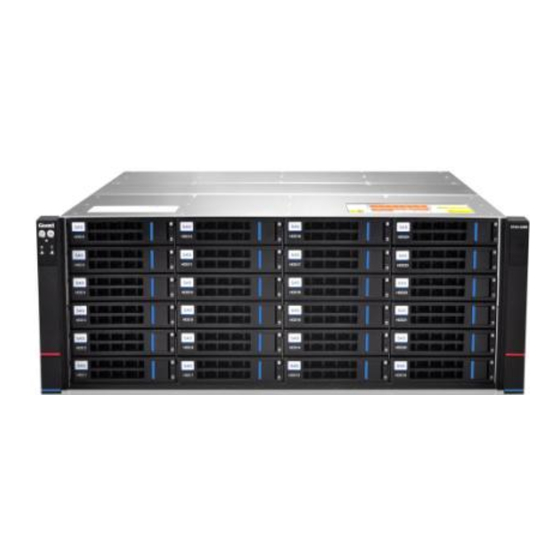
Voltage: 8.5~13.2V, current: 1.60A, maximum 1.76A. Power: maximum 23.2W. Maximum speed: 3600 +/- 10% RPM. Air flow: 4.657 m3/min (164.39 CFM), minimum 3.379 m3/min (119.3 CFM). Pressure: 146.9538 Pa. 1.4 System View 1.4.1 Front View Shenzhen Gooxi Technology Co., Ltd. - Page 9 Each module has its own status of LED display, described in the following table: LED status description image LED appearance description LOGO blue light is ① Device startup always on ② Green light is on Device startup Shenzhen Gooxi Technology Co., Ltd.
- Page 10 Hard disk in place indication 1.4.4 Hard Disk Indicators Act LED (green) Fault LED (yellow) Status LED (blue) ⑴ Act LED (green light) ⑵ Fault LED (yellow light) ⑶ Status LED (blue light) ⑷ LED description as shown below: Shenzhen Gooxi Technology Co., Ltd.
- Page 11 Hard disk in Chang Liang place Hard disk Flashing 4Hz/s activity Hard disk Chang Liang Flashing 4Hz/s positioning Hard disk Chang Liang Chang Liang error RAID Flashing reconstructi Chang Liang 1Hz/second 1.4.5 Hard Disk Sequence Introduction Shenzhen Gooxi Technology Co., Ltd.
- Page 12 Shenzhen Gooxi Technology Co., Ltd.
-
Page 13: Chapter Ii System Interface Introduction
Chapter II System Interface Introduction 2.1 Overview The main interfaces of the system are distributed on the main board. The following content mainly introduces the interface layout of the main board. 2.1.1 G2SCW-4B MOTHERBOARD REAL PICTURE Shenzhen Gooxi Technology Co., Ltd. - Page 14 8Pin BIOS debug socket and BIOS chip I210 1000M Data LAN port 1 LAN1/NCSI Simultaneous use of NCSI as BMC IPMI LAN port (100M) LAN2 I210 1000M Data LAN port 2 LAN3 I210 1000M Data LAN port 3 Shenzhen Gooxi Technology Co., Ltd.
- Page 15 Airmax high Airmax VSe high speed signal hot swap J1/J2/J3 speed signal connector for high speed signal support connector 12Gb/s Airmax Power Airmax hot-swappable connector for Plug power transfer Connector Shenzhen Gooxi Technology Co., Ltd.
-
Page 16: Motherboard Io Interface
System power AC terminal is not connected 2.2.2 S ID ( YSTEM IDENTITY INDICATOR The system ID indicator is designed to allow the user to more intuitively identify which device the current operation is on. The specific location of the Shenzhen Gooxi Technology Co., Ltd. - Page 17 Used by ports, the LED indicators of the network port are as follows: IPMI LAN Port LED description Link status indicator: Left LED 1. Gigabit Link, green long bright Shenzhen Gooxi Technology Co., Ltd.
- Page 18 3. Ten mega Link, LED is off; The yellow light flashes when there is data activity; Right Led When no data activity, the indicator does not light; / Note: The two network port indicators are the same. Network port location diagram: Shenzhen Gooxi Technology Co., Ltd.
- Page 19 Controller, a 15PIN VGA Connector is used to access the VGA monitor, this VGA port is connected from the motherboard's VGA pin to the VGA cable to be fixed in the controller casing IO position . Shenzhen Gooxi Technology Co., Ltd.
- Page 20 Ground 2.2.8 SATA DOM POWER CONNECTOR (J26 POSITION The motherboard design reserved 3PIN Power Connector for SATA DOM access power. PIN is defined as follows: SATA DOM POWER Connector Pin Definition PIN sequence description PIN1 Shenzhen Gooxi Technology Co., Ltd.
- Page 21 The board is designed with four DDR4 SLOTs and is divided into Channel A and Channel B. Each channel has two DIMM SLOTs. / Note: If only one DIMM is inserted in each Channel, it needs to be inserted in the slot away from the CPU. Shenzhen Gooxi Technology Co., Ltd.
- Page 22 J6 is LGA1151 CPU SOCKET. It is used to load LGA1151 CPU. During the installation of CPU, attention must be paid to the installation of the first PIN. The first PIN shown below is indicated by a triangular arrow and corresponds to the triangular arrow of the CPU. Shenzhen Gooxi Technology Co., Ltd.
- Page 23 When the SATA SSD is low, the BIOS configures PICE0/SATA0 as PCIE or SATA by checking the High Low of this GPIO. 2.2.13 M EZZANINE CONNECTOR Mezzanine connector, pinch connector to PCIEX8 signal, used to plug 12Gb SAS card. Shenzhen Gooxi Technology Co., Ltd.
-
Page 24: Connection Cable
ME functions. However, the Firmware update and upgrade of ME is not limited. Under normal circumstances, it cannot be shorted. J16 introduction: Use 2PIN adjustment cap to insert J16, then use Clear CMOS. 2.5 Power Module Shenzhen Gooxi Technology Co., Ltd. -
Page 25: Led Definitions In The Motherboard
UID LED description description The UID LED is the identity indicator on the motherboard. The user can use the IPMI to control the indicator to be on or off and to be blue when lit. BMC(AST24 Shenzhen Gooxi Technology Co., Ltd. - Page 26 Green is 1HZ flashing, the system has a CPU, but no boot is in standby mode; Yellow long bright system detects fault (overheat/fan/power failure and alarm);; none is off AC not powered or AC powered but CPU/BMC is not installed Shenzhen Gooxi Technology Co., Ltd.
- Page 27 4. BMC Heart LED BMC Heart LED description Green light flashes at 1Hz Firmware initialization OK This indicator cannot be lit Firmware did not complete initialization 5. Motherboard PWR OK LED PWR OK LED description Shenzhen Gooxi Technology Co., Ltd.
- Page 28 Board PWR OK LED status LED description Location Onboard power OK Green LED is always D12 (front) green Board power is not OK Green LED is off off state SATA HDD/M.2 SSD is not in Green LED off Shenzhen Gooxi Technology Co., Ltd.
- Page 29 Shenzhen Gooxi Technology Co., Ltd.
-
Page 30: Chapter 3 Detailed Controller Module Installation
CPU, heat sink, memory, fan module, backplane, PIKE card, and expansion card. 3.1 The front view of the module as follows: 3.2 The module opens the upper cover and the internal picture as follows: Shenzhen Gooxi Technology Co., Ltd. -
Page 31: Cpu Installation
3. If you purchased a CPU cooler separately, make sure you are using a Goixi Certified Heatsink. Detailed installation of LGA1151 processor steps: 1) Press gently on the platen and push outwards (to the right) to unlock. Shenzhen Gooxi Technology Co., Ltd. - Page 32 2) Once the pressure plate handle is unlocked, gently lift the handle to open the pressure plate. Shenzhen Gooxi Technology Co., Ltd.
- Page 33 5) Once they are aligned, carefully insert the CPU straight down into the slot. (To avoid damage to the CPU or socket, do not rub the surface of the CPU Shenzhen Gooxi Technology Co., Ltd.
-
Page 34: Cpu Heatsink Installation
First tighten the two diagonal screws until they are just in place (to avoid damage to the CPU and heat sink, do not overtighten the screws). Tighten the four bolts fully to complete the installation. Reverse the sequence of this process to remove the heat sink. Shenzhen Gooxi Technology Co., Ltd. -
Page 35: Memory Installation
OW TO INSTALL MEMORY Motherboard DIMM slot sequence: DIMMA0, DIMMB0, DIMMA1, and DIMMB1, pay attention to the memory of the hole and the DIMM slot gap to prevent incorrect installation. Vertically snap each DIMM module into place. Shenzhen Gooxi Technology Co., Ltd. - Page 36 DIMM. Installation: Insert the memory module vertically and press the memory slot snap-in position. Note the bottom of the alignment notch. Notch Simulate the demo diagram inserted into the memory bar: Shenzhen Gooxi Technology Co., Ltd.
-
Page 37: Expansion Card Installation
Simulate the demo picture of disassembling the memory: 3.4 Expansion Card Installation 1) First install the expansion card to the PCIE riser card and secure it to the bracket with screws. The schematic diagram is as follows: Shenzhen Gooxi Technology Co., Ltd. - Page 38 PCIE riser card vertically. / Note: Lock the screws. 2) Install the expansion card and PCIE riser card to the motherboard, and fix the bracket with screws. The schematic diagram is as follows: Shenzhen Gooxi Technology Co., Ltd.
- Page 39 / Note: Make sure the PCIE riser card is in place. / Note: Lock the screws. Shenzhen Gooxi Technology Co., Ltd.
-
Page 40: Chapter 4 Chassis Installation
Chapter 4 Chassis Installation 4.1 Backplane and SPIB Board Installation 4.1.1 Installation diagram of the backplane is as follows: Shenzhen Gooxi Technology Co., Ltd. - Page 41 Shenzhen Gooxi Technology Co., Ltd.
- Page 42 /Note: Make sure that the backboard is inserted vertically, and fix the fixing screws on three sides Shenzhen Gooxi Technology Co., Ltd.
- Page 43 Shenzhen Gooxi Technology Co., Ltd.
- Page 44 4.1.2 The schematic diagram of installing the SPIB board is as follows: / Note: When installing or removing the SPIB board, pay attention to the components in the PCBA and do not collide with the chassis. Shenzhen Gooxi Technology Co., Ltd.
-
Page 45: Fan Installation
Installation complete diagram 4.2 Fan Installation The system adopts modular fan wall heat dissipation, and the wind wall support module has no screws and no tools to install. The installation diagram is as follows: Shenzhen Gooxi Technology Co., Ltd. - Page 46 / Note: The notch of the fan wall is aligned with the snap on the chassis, and then the power cable of each fan is connected to the backplane. Shenzhen Gooxi Technology Co., Ltd.
-
Page 47: Controller Module Installation
Installation complete diagram 4.3 Controller Module Installation The system adopts a modular installation and supports hot swap; installation and maintenance are simple and convenient. The installation diagram follows: Shenzhen Gooxi Technology Co., Ltd. - Page 48 ① ② Shenzhen Gooxi Technology Co., Ltd.
-
Page 49: Hard Disk Installation
③ 4.4 Hard Disk Installation The whole system supports 16 3.5-inch hard disks. The installation method of each hard disk is the same. The following installation diagrams are as follows: Shenzhen Gooxi Technology Co., Ltd. - Page 50 ① ② Installation complete diagram Shenzhen Gooxi Technology Co., Ltd.
- Page 51 Shenzhen Gooxi Technology Co., Ltd.
-
Page 52: Chapter 5 System Installation
The ST401-S36REH storage server barebone system uses a full set of screwless tool-free rails for easy installation. Rails Use the following procedure to install the system into the cabinet. Pull out the inner rail of the guide rail. As shown below: ① Shenzhen Gooxi Technology Co., Ltd. - Page 53 ② ③ Install the extracted inner rail into the chassis as shown below. Shenzhen Gooxi Technology Co., Ltd.
- Page 54 ① ② Shenzhen Gooxi Technology Co., Ltd.
- Page 55 ③ Secure the rails to the cabinet and pull out the middle rail. As shown below: Shenzhen Gooxi Technology Co., Ltd.
- Page 56 ① Shenzhen Gooxi Technology Co., Ltd.
- Page 57 ② Put the system in cabinet horizontally into the guide rail and push in the cabinet. As shown below: Shenzhen Gooxi Technology Co., Ltd.
- Page 58 The left buckle is lifted upwards, and the right buckle is pressed downwards to continue pushing. As shown below: The left side of Press down on the buckle right side lifted up Lock the fixing screw, as shown below: Shenzhen Gooxi Technology Co., Ltd.
- Page 59 The final schematic diagram of putting the entire storage server system into cabinet is as follows: Shenzhen Gooxi Technology Co., Ltd.
- Page 60 The cabinet must be secured, and instability in the cabinet may cause the cabinet to tip over. Shenzhen Gooxi Technology Co., Ltd.
- Page 61 100-240V 47Hz~63Hz。 Input voltage The output +12V_SB, +12V voltage System fan Number of fans The system supports three 12038 temperature-controlled fans 12(8.5-13.2)V Fan voltage 1.60(1.76 Max) Fan current speed of the Maximum 3600 +/- 10% RPM Shenzhen Gooxi Technology Co., Ltd.
- Page 62 Linux Kernel Virtual Machine (Target) System ambient temperature System Operating temperature: 10°C ~ 35°C; non-operating temperature: operating -40°C ~ 70°C temperature System Operating humidity: 35%~80%; Non-operating humidity: 20% ~ 90% temperature and humidity Safety certification CE ROHS Certified Shenzhen Gooxi Technology Co., Ltd.
Need help?
Do you have a question about the ST401-S36REH-G2 and is the answer not in the manual?
Questions and answers