
Subscribe to Our Youtube Channel
Related Manuals for Gooxi SL401-G2


Summary of Contents for Gooxi SL401-G2
- Page 1 SL401-G2 Rackmount Server User Manual Document version : 01 Release date: 2022/11/29 Shenzhen Gooxi Information Security Co., Ltd.
-
Page 2: Statement
Gooxi provides this user manual "as is" and to the extent permitted by law, makes no express or implied warranties or guarantees, including but not limited to merchantability, fitness for a particular purpose, non-infringement of any rights of others, and any warranties or guarantees regarding the use or inability to use this user manual. -
Page 3: Foreword
Foreword This manual is the product technical manual for the Gooxi Eagle Stream platform 2U model servers. It primarily provides an introduction and explanation of the product's appearance, structure, hardware installation, and basic configuration. Please note that this manual is intended for reference and research purposes for professional technical personnel. -
Page 4: Table Of Contents
Contents Statement..............................1 Foreword..............................2 1. Product Introduction ..........................5 1.1 Product Overview ........................5 1.2 Product Structure ......................... 6 1.3 Logical Structure ......................... 7 1.4 Product Specifications ......................... 9 2. Hardware Description .......................... 10 2.1 Front Panel ..........................10 2.1.1 Appearance ........................10 2.1.2 Indicator lights and buttons .................. - Page 5 3.2.2 Heatsink installation ....................29 3.2.3 Memory installation ....................30 4. Configuration Instructions ........................32 4.1 Initial Configuration ....................... 32 4.1.1 Power on and start ....................... 32 4.1.2 Initial data ........................34 4.1.3 Configure BIOS ......................34 4.1.4 Configure BMC ......................35 Appendix..............................40...
-
Page 6: Product Introduction
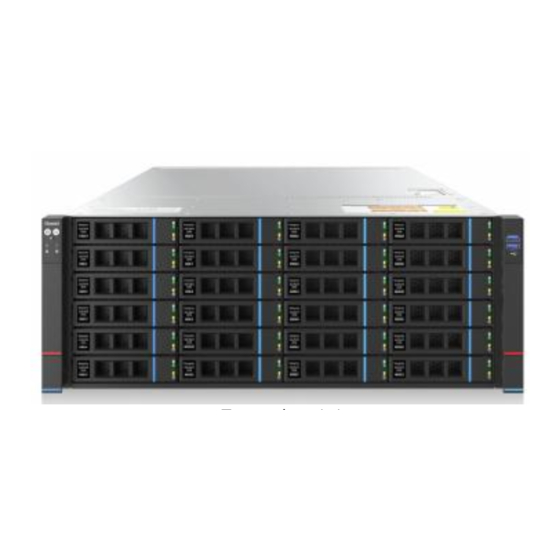
1.1 Product Overview SL401 Purley 4U dual-socket rackmount server is a new generation 4U dual-socket rack server launched by Gooxi to meet the diverse needs of the Internet, IDC (Internet Data Center), cloud computing, enterprise markets, and telecommunications services. It is... -
Page 7: Product Structure
Rear view of 24-bay configuration 1-2 Rear view of 36-bay configuration 1-3 1.2 Product Structure Product exploded view of SL401 Purley 4U dual-socket rack server (example of 36-bay model) Structure diagram 1-3 Name Name Wind shield Fan module Memory slot Fan rack Motherboard PCIE module... -
Page 8: Logical Structure
IO panel Front hard drive module OCP 3.0 Top cover Chassis Rear hard drive module Table 1-1 1.3 Logical Structure The logic of the SL401 Purley 4U dual-socket rack server is as shown in the following diagram: Motherboard logic block diagram 1-4 The CPU uses the third generation Intel®... - Page 9 SFF8643 connector, and the rear 2 ports are introduced to 7PIN SATA connectors for connecting SATA DOM and DVD. The BMC (Baseboard Management Controller) chip in the motherboard uses the AST2500 control chip from ASPEED company for IPMI remote management. It includes a VGA output port, a dedicated Gigabit RJ45 management network port, and is connected to the PCH via RMII/NCSI.
-
Page 10: Product Specifications
1.4 Product Specifications Product Series SL401-D24RE SL401-D36RE 4U24 bay 4U36 bay Product Type System Size 798 *433.4* 176.5 mm (depth*width*height) Processor Supports 1 or 2 3rd generation Intel® Xeon® Scalable series processors 24 DDR4 memory slots, supporting DDR4 LRDIMM/RDIMM2400/2666 /2933 MHz; the maximum capacity of a single slot is 256GB, compatible Memory with Optane memory, and the entire machine supports a maximum memory capacity of 9 TB... -
Page 11: Hardware Description
2. Hardware Description 2.1 Front Panel 2.1.1 Appearance 24x3.5 -inch hard drive configuration Figure 2-1 Name Name Left ear assembly Right ear assembly 3.5-inch hard drive Table 2-1 36 x3.5-inch hard drive configuration Figure 2-2... -
Page 12: Indicator Lights And Buttons
VGA interface Rear 3.5-inch hard drive Table 2-2 2.1.2 Indicator lights and buttons Figure 2-3 Indicator light/button Indicator light/button GOOXI logo Hard drive indicator light Power switch button/indicator System alarm indicator light light Network port 1 connection status UID button/light... -
Page 13: Interface
UID Button/Indicator Light is used for conveniently locating the server to be operated. It can be turned on or off manually by pressing the UID button or remotely controlled via BMC command. UID button/light UID Indicator Light Explanation: Blue (Solid/Blinking): Indicates the server is located. Off: Indicates the server is not located. -
Page 14: Rear Panel
Quantity Name Type Description USB interface USB 3.0 For connecting USB devices Table 2-5 2.2 Rear Panel 2.2.1 Appearance Rear panel appearance Figure 2-5 Name Name Riser 1 module I/O port Riser 2 module OCP Network card (optional) Riser 3 module Power module 1 Riser 4 module Power module 2... -
Page 15: Interface
Figure 2-6 Name Name Management network port UID indicator light connection status indicator Management network port data OCP Network port indicator transmission status indicator light Network port connection status Power module indicator light indicator light Network port data transmission Power module indicator light status indicator light Table 2-8 Power module indicator light description... -
Page 16: Processor
Processors configured on the same server must be of the same model. For specific optional system configurations available for purchase, please consult with Gooxi sales. The location of the processor is as shown below: Figure 2-8... -
Page 17: Memory
2.4 Memory 2.4.1 Memory slot location The motherboard supports 12 DDR4 channels, with each channel supporting 2 DIMMs. With 2 CPUs, a total of 24 DDR4 slots are supported. (When only one memory module is inserted, it is preferred to insert it into the slots marked in red in the diagram below. The slots on the motherboard are colored blue.) memory slot location ... -
Page 18: Storage
Cascade Lake CPU: L-series CPUs support a maximum memory capacity of 4.5TB per socket. M-series CPUs support a maximum memory capacity of 2TB per socket. Other models support a maximum memory capacity of 1TB per socket. The calculation formula for total memory capacity supported is as follows: Total memory capacity equals the sum of the capacities of all DDR4 memory modules. -
Page 19: Hard Drive Status Indicator
36 x3.5-inch hard drive configuration Front 24-bay figure 2-11 Rear 12-bay figure 2-12 2.5.3 Hard drive status indicator Figure 2-14 Hard drive status indicator light description Function Act LED Status LED Fault LED Hard drive in Steady on place hard drive Flashing... -
Page 20: Power Supply
For power modules configured on the same server, the power module models must be the same. For specific optional system options, please consult Gooxi sales. The power supply location is shown in the figure below: Figure 2-14 2.7 Fans... -
Page 21: Pcie Slot Description
Figure 2-15 The slots provided by the Riser1 module are Slot 0, Slot 1, and Slot 2. When using a 2-slot PCIE expansion module, Slot 1 is unavailable. The slots provided by the Riser2 module are Slot 3, Slot 4, and Slot 5. When ... -
Page 22: Pcie Expansion Module
Slot 9 CPU 1 PCIe 3.0 1 slot PCIE Expansion module:X16 half height 2 slots PCIE Expansion module:X8 half length Note: ◆Slots with a bus bandwidth of PCIe x16 are backward compatible with PCIe cards of PCIe x8, PCIe x4, and PCIe x1. It is not compatible upward, that is, the bandwidth of the PCIe slot cannot be less than the bandwidth of the inserted PCIe card. - Page 23 Figure 2-19 2.5-inch hard drive module Figure 2-20...
-
Page 24: Pcba
2.9 PCBA 2.9.1 Motherboard Motherboard Figure 2-21 Name 4U Chassis fan control 4 pins interface Memory slot (corresponding to CPU 0) Memory slot (corresponding to CPU 1) CPU 0 CPU 1 GPU Power 2*4 pin interface BP Power 2*4 pin interface SFF 8643 SATA interface USB 3.0 interface BP I 2C interface... -
Page 25: Hard Drive Backplane
LAN RJ 45 1Gb * 2 DB -9 COM port USB 3.0 OCP 82599 CPU 1 PCIe 4.0 X16 CPU 1 PCIe 4.0 X8 BP HDD led Slimline PCIe 4.0 X8 CPRS PSU GPU Power CPRS PSU RISER POW BP Power FP BIN led PMBUS / BP 5 I2C FP VGA... - Page 26 Figure 2-23 Description Function Backplane power transmission ATX power input connector, used for 12V power transmission Temperature controlled For 4pin fan interface fan socket Expander chip controller PM8044 SXP 24Sx12G 24- port 12G SAS Expander CPLD Used for data logic processing SFF-8643 12Gb SAS Backplane bay signal interface interface...
- Page 27 Figure 2-25 Description Function Temperature controlled fan 1, 2, 3, 4 For 4pin fan interface socket MINI SAS HD High Speed For transmission of 12G/b SAS or Connector 6G/b SATA signals Backplane power transmission power connector connector, used for 12V power transmission PM8043 SXP 24Sx12G EXPANDER chip...
- Page 28 Description Function 1, 5 7PIN SATA interface SATA disk signal cable interface Temperature sensor IC temperature sensor chip Used for hard drive LED SGPIO lighting signal positioning lighting and fault LED indication functions. I2C interface For I2C signal interface Backplane power transmission Power interface connector, used for 12V power transmission...
-
Page 29: Installation Instructions
3. Installation Instructions 3.1 Chassis Top Cover Installation Step 1: Align the hooks on the top cover with the openings on the chassis, and place it downwards. Step 2: Rotate the top cover lock latch in the direction of the arrow until it ... -
Page 30: Heatsink Installation
Figure 3-3 3.2.2 Heatsink installation Step 1: Remove the processor idle bracket. (As shown in the figure below) Figure 3-4 Step 2: Align the heatsink with the heatsink mounting screws on the CPU socket, and tighten the heatsink mounting screws in the indicated sequence. (As shown in the figure below) Figure 3-5 Caution: The pins on the motherboard are very fragile and can be easily... -
Page 31: Memory Installation
3.2.3 Memory installation The six memory slots controlled by CPU1 are: DIMMA1, A2, DIMMB1, B2, DIMMC1, C2; The six memory slots controlled by CPU2 are: DIMMD1, D2, DIMME1, E2, DIMMF1, F2. Ensure that the notch on each memory module aligns with the slot's notch and insert the DIMM vertically to ensure correct installation and prevent any errors. - Page 32 Table 3-1 Note: If the situation involves the 5th, 7th, 9th, 10th, or 11th memory slot, it must adhere to the following rules: Single memory modules should be inserted into the blue slots on the motherboard; For dual memory module configurations, follow the configuration of the nearest memory slots as mentioned above, then add additional memory accordingly.
-
Page 33: Configuration Instructions
4. Configuration Instructions 4.1 Initial Configuration 4.1.1 Power on and start Before powering on, it is necessary to ensure that all configurations of the server are installed in accordance with the corresponding specifications and standards, and keep the server turned off but not unplugged from the power supply. - Page 34 Figure 4-1 PCH state after G3 PCH state setting after G3, the menu options are: S0: Power on and start up directly. S5: You need to press the Power button to turn on the power. leave power state unchanged: Leave the power state unchanged. Default: S0 Log in to the iBMC management interface to perform remote power-on and ...
-
Page 35: Initial Data
Figure 4-2 For detailed usage of BMC and BIOS, please view the corresponding user manual. 4.1.2 Initial data BMC default account: admin BMC default password: Gooxi@123. BMC default address: 192.168.100.1 BIOS Default Password: None 4.1.3 Configure BIOS Press the <DEL>... -
Page 36: Configure Bmc
Figure 4-3 The Main interface contains the basic information of the BIOS system, such as the BIOS version number, CPU model, memory capacity, and the system time can be set. For detailed instructions, please refer to the "BIOS User Manual". Navigation key description: ... - Page 37 After the server powers on, pay attention to the POST process. Press the <DEL> or <ESC> key on the keyboard to enter the BIOS Setup interface. Switch to the following interface: Figure 4-4 Configure IPV4 support : BMC sharelink Management Channel ...
- Page 38 Configuration Address source Configure the BMC IP address allocation mode, the menu options are: Unspecified: No change to BMC parameters Static: BIOS static IP setting DynamicBmcDhcp: BMC runs DHCP to dynamically assign IP DynamicBmcNonDhcp: BMC runs the Non-DHCP protocol to dynamically assign IP Default: Unspecified When changing from "Unspecified"...
- Page 39 Disabled: does not support IPV6 Default: Enabeld When changing from "Unspecified" to other parameters, saving and rebooting will result in the options reverting to the "Unspecified" value. There is no need to configure the BMC IP during every startup process. When the "Configuration Address Source"...
- Page 40 Figure 4-6 This page sets the IP address of the BMC management network port.
-
Page 41: Appendix
If the above steps do not resolve the issue, try replacing the monitor with a known working one to confirm if the original monitor is faulty. If the issue persists, please contact Gooxi's customer service department for resolution. Front Panel Indicator Lights Alarm Refer to the instructions in the manual to determine the specific alarm information indicated by the front panel lights and buttons. - Page 42 Set static or dynamic IP and ensure ping connectivity. If the web interface does not open, try using a newer version of Internet Explorer. If the problem is not resolved, please contact Gooxi’s customer service department for further assistance and resolution.
Need help?
Do you have a question about the SL401-G2 and is the answer not in the manual?
Questions and answers