
Subscribe to Our Youtube Channel
Related Manuals for Gooxi SL101-D04R-G3


Summary of Contents for Gooxi SL101-D04R-G3
- Page 1 Whitley Platform L-shaped Server Barebones User’s Manual V1.0 Shenzhen Gooxi Information Security Co., Ltd.
- Page 2 This user manual, including but not limited to all the information contained in it, is protected by Copyright Law. Without the permission of Shenzhen Gooxi Information Security Co., Ltd. (hereinafter referred to as "Gooxi"), it is not allowed to imitate, copy, extract, redistribute or use for other purposes.
- Page 3 Jtag Joint Test Action Group, a joint test working group, mainly used for internal chip testing NC Pin Empty pin Extend Debug Port, Intel CPU debugging interface ® Glossary: Abbreviation Original Chinese meaning Platform Controller Hub 即之前统称的“南桥” Gigabit Ethernet 千兆以太网 Baseboard Management Controller 基板管理控制器...
- Page 4 Error Correcting Code 错误检查和纠正 Cubic Feet Per Minute 立方英尺每分钟 Revolution Per Minute 转每分 Conventions: Note: Used to convey equipment or environmental safety warning messages, which, if not avoided, may result in equipment replacement, data loss, reduced equipment performance, or other unpredictable results.
-
Page 5: Table Of Contents
CONTENTS CHAPTER 1 SAFETY STATEMENT ............................. 8 1.1 G ................................. 8 ENERAL SAFETY MATTERS 1.2 T ..................9 OXIC AND HAZARDOUS SUBSTANCES OR ELEMENTS IN PRODUCTS 1.3 W ....................................10 ARNING NOTICES 1.4 C ........................10 LIMATE AND NVIRONMENTAL EQUIREMENTS 1.5 O .............................. - Page 6 CHAPTER 5 BIOS PARAMETER SETTINGS ........................58 5.1 E BIOS S ...............................58 NTER THE ETUP INTERFACE 5.2 S ............................58 ETUP MENU PARAMETER DESCRIPTION 5.2.1 Navigation Key Description ..............................58 5.2.2 Main menu description ................................58 5.2.3 Advanced menu description ..............................60 5.2.4 Trusted Computing ..................................
- Page 7 5.2.46 Security menu ..................................111 5.2.47 Boot menu ....................................112 5.2.48 Save & Exit menu .................................. 113 5.3 U ................................. 113 PERATION EMINDER CHAPTER 6 RAID SETUP INSTRUCTIONS ........................115 6.1 PCH RAID ................................. 115 CONFIGURES 6.1.1 Configuring RAID in UEFI Boot Mode..........................115 6.1.2 Configuring RAID in Legacy Boot Mode..........................122 6.2 RAID RAID ..............................
-
Page 8: Chapter 1 Safety Statement
Make sure the computer is well grounded. Different grounding methods are possible, but they must be physically connected to ground. If you are not sure whether the grounding protection is safe, please contact the appropriate agency or electrician to confirm. If cable routing is required, please contact Gooxi Hengyun Information Security Co., Ltd. for advice. -
Page 9: Toxic And Hazardous Substances Or Elements In Products
Please keep the environment clean and avoid dust. The temperature of the equipment working environment is 10℃~40℃, and the humidity is 35%~80%. Please back up important data in time, Shenzhen Gooxi Information Security Co., Ltd. is not responsible for data loss caused by any circumstances. -
Page 10: Warning Notices
. However, it complies with the EU RoHS Directive (including its exemption provisions). Note: the table shows the information of toxic and hazardous substances in all possible components of Gooxi server, storage and workstation products. Customers can refer to the status of toxic and hazardous substances in all components of the purchased products according to this table. -
Page 11: Other Important Descriptions
Choosing a suitable environment for the computer is helpful for the stable operation and can prolong the life of the computer. Shenzhen Gooxi Information Security Co., Ltd. reserves the right of final interpretation of the above terms 1.5 Other important descriptions If the equipment is marked with a label, it means that the equipment with the label is only designed and evaluated as the altitude of 2000m. -
Page 12: Chapter 2 Product Introduction
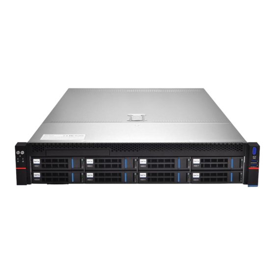
Chapter 2 Product Introduction 2.1 System introduction Gooxi Whitley dual-socket L-shaped series servers are based on the Intel Whitley platform, and are widely used 1U, 2U, 4U dual-socket servers for the Internet, IDC (Internet Data Center), cloud computing, enterprise market and telecom business applications. Rack-mounted L-shaped storage server. It is suitable for high-density deployment of loads such as cloud computing, virtualization, high-performance computing (HPC), and big data processing to improve data center space utilization. - Page 13 hot-swap SATA/SAS HDDs, and the rear upper layer is optional and supports 2* 2×3.5 inch SAS/SATA or 2* 2×2.5 inch SAS/SATA or NVME hot-swap hard drives. Front port: 2 USB3.0, 1 VGA port External port Rear: 1 VGA, 1 DB-9COM port, 2 USB3.0, 1 RJ45 Gigabit management LAN port, 2* Gigabit/10 Gigabit RJ45 network ports ASPEED AST2500 Support 2 PCIe 4.0 x32 slots (can be converted into various types of PCIE slots...
-
Page 14: System Architecture
Working humidity 35% ~ 80% Storage -40℃ ~ 70℃ temperature Storage humidity Humidity: 20%~90% (including packaging) Table 1- 4 2.2.2 System Architecture SL series server products include 1U models (SL101-D04R, SL101-D10R), 2U models (SL201-D08R, SL201-D12RE, SL201-D12R, SL201-D25RE, SL201-D08R-NV, SL201-D12R-NV) 4U models (SL401-D24RE, SL401-D36RE) bays, motherboard name: G4DCL-B, the models are the same except for the hard disk connection method and the maximum number of compatible hard disks. -
Page 15: Introduction Of System Components
Figure 2- 1 2.3 Introduction of system components 1U4 bay model Product SL101-D04R-G3 name Processor Supports one or two 3rd Generation Intel Xeon Scalable processors ® ® MB model G4DCL Supports DDR4 RDIMM/LRDIMM server memory; memory frequency supports 2400/2666/2933/3200MHz ;... - Page 16 Supports AC220V 550W, 800W, 1300W, 1600W, 2200W redundant power supply Power (according to actual power adaptation) supply Supports HVDC 240V ~ 336V 550W 800W 1300W Supports LVDC -48V 550W 800W 1300W Dimensions 1U rackmount, 748*433.4* 43.6mm 1U10 bay model Product SL101-D10R/NV-G3 name...
- Page 17 Supports DDR4 RDIMM/LRDIMM server memory; memory frequency supports 2400/2666/2933/3200MHz ; Single CPU supports 8 DDR4 channels, each channel supports 2 DIMMs, and supports a Memory total of 32 DDR4 slots; single capacity: 16GB, 32GB, 64GB, 128GB, 256GB , and the whole system supports a maximum memory capacity of 12TB Note: In order to make the system more stable, it is recommended to use the AVL MEMORY LIST...
- Page 18 On-board 2 Gigabit RJ45 data LAN ports Front Port: 2 USB3.0, 1 VGA External Rear port: 1 VGA, 1 COM port, 2 USB3.0, 1 RJ45 Gigabit management LAN port, 2 port Gigabit RJ45 LAN ports On-board iBMC management module, supports IPMI, SOL, KVM Over IP, virtual media Management and other management features 4* 8038 hot-swap N+1 redundant fans;...
-
Page 19: Front Panel Components
2.3.1 Front Panel Components 1U4-bay model Serial Name Serial Name number number Left ear VGA port Front Panel Indicators Right ear USB3.0 port 3.5 inch hard drive 1U10-bay model Serial Name Serial Name number number left ear USB3.0 port Front Panel Indicators 2.5 Hard Disk Right ear 2U8-bay model... - Page 20 2U12-bay model Serial Name Serial Name number number 3.5 inch hard drive USB3.0 port VGA port Table 1- 9 2U25-bay model Serial Name Serial Name number number 2.5 inch hard drive USB3.0 port VGA port 4U24/36-bay model Serial Name Serial Name number number...
- Page 21 LED Status Description Indicator/ Logo Status Description Button GOOXI logo Power indicator description: Green (on): Indicates that the device is powered on normally. Green (flashing): Indicates that the device is in standby. Green off: The device is not powered on.
-
Page 22: Rear Panel Components
Short press this button in the power-on state to start the machine. The UID button/indicator is used to conveniently locate the server to be operated. The UID button can be manually pressed or the BMC command can be remotely controlled to turn the light off or on. UID button/ Description of UID indicator: indicator... - Page 23 Figure 2- 9 Serial Name Serial Name number number Riser module USB 3.0 port Hard disk module OCP3.0 port Management network port Power Module 1 VGA port Power Module 1 AC port RJ45 Gigabit Ethernet port Power Module 2 COM port Power Module 2 AC port Table 1- 14 ...
-
Page 24: Rear Panel Port Description
Management network port Power switch button VGA port Power Module 1 RJ45 Gigabit Ethernet port Power module AC port 1 COM port Power Module 2 USB 3.0 port Power module AC port 2 UID indicator Figure 2- 10 Serial Name Serial Name number... -
Page 25: Motherboard Components
Button Green (on): Indicates that the input and output are normal. Red (on): Indicates that the input is normal, and there is no output due to power supply over-temperature protection, power output over-current/short-circuit, output over-voltage, short-circuit protection, device failure (excluding all device failures) Power Module and other reasons. - Page 26 Default Name Remarks BMC_UART5, BMC debug serial port Used for CPU0 VR upgrade and programming, the jumper cap is not connected by default For CPU1 VR upgrade and programming, the jumper cap is not connected by default Front VGA mounting ear connector Front USB 3.0 connectors (x2) Built-in USB3.0 connector Rear USB3.0 connector q(x2)
- Page 27 FAN1~FAN9 6 P in fan connector (total 9 pcs) J40~J47 4 P in fan connector (total 8 pcs) SATA1/SATA2 SATA DOM CONN (SATA 7 Pin) (with PWR design) J37/J38 SATA DOM PWR CONN Chassis Intrusion Header, Chassis Intrusion Detection Slimline PCIe X 8 CONN (defined by SFF-9402 J24/J25 standard) Buzzer...
-
Page 28: Hdd Backplane Components
PCH I2C Header Pin.1/2 Clear CMOS Pin.3/4 Password Clear No Jumpers Pin.5/6 ME FW Recovery Status Pin.7/8 BMC Disable Pin.9/10 BIOS Recovery Mode Enable SD Card Slot (BMC Log Storage) OCP1 OCP3.0 Slot (CPU0 PCIE X8) J17+J18+J19 Riser1 Slot (CPU0 PCIE X32) J20+J21+J22 Riser2 Slot (CPU0 PCIE X32) Riser3 Slot (CPU1 PCIE X16) - Page 29 Serial Description Function number 1. Maximum support 12G/b SAS hard disk; SAS0~7 SAS/SATA hard drive connector 2. Maximum support 6G/b SATA hard disk; 3. Support SAS/SATA hard disk hot-swap. Bottom view: Serial Description Function number Backplane power transfer connector for 12V 1, 2 ATX power input power transfer...
- Page 30 Bottom view: Serial Description Function number Temperature Controlled Fan 1, 2, 3, 4 For 12G/b SAS or 6G/b SATA signal transmission. Socket Backplane power transmission connector for 12V 5, 6, 7 Power connector power transmission. PM8043 SXP 24Sx12G EXPANDER chip 24-port 12G SAS Expander MINI SAS HD High Speed For 12G/b SAS or 6G/b SATA signal transmission.
- Page 31 MINI SAS HD High Speed For 12G/b SAS or 6G/b SATA signal transmission Connector Backplane Snap Fasten the backplane to the backplane bracket EXPANDER chip PM8043 SXP 24Sx12G 24-bay expansion backplane as shown Serial Description Function number Backplane power transfer connector for 12V and 5V BP power interface power transfer Fan interface...
- Page 32 Serial Description Function number 1. Maximum support 12G/b SAS hard disk; SAS/SATA connector 2. Maximum support 6G/b SATA hard disk; 3. Support SAS/SATA hard disk hot swap. Table 1- 24 Bottom view: Serial Description Function number Temperature sensor IC Temperature sensor chip 2, 5 7PIN SATA port SATA disk signal line port...
- Page 33 Serial Description Function number Provides PCIe×4 interface to connect to CPU and NVME 1, 4 Slimline 4i Connector SSD1 (including CPU PEHP I2C and BMC I2C signals) CPLD chip For data logic processing JTAG debug interface for programming and version JATG debugging interface upgrade of CPLD 4 Pin power socket for docking with PSU or docking with...
- Page 34 LED Indicator Description Serial Description Function number Green/ yellow indicator for indicating LAN1 speed Green: 10 Gigabit Internet speed ; Yellow : Gigabit SFP+ LAN1 Link LED Internet speed LED1 No light: no optical port network cable Green light for LAN1 data activity SFP+ LAN1 ACT LED Flashing: data activity ;...
- Page 35 Serial Description Function number PCIE 3.0 X8 Slot For PCIe 3.0 X8 devices. PCIE X16 Gold finger For motherboard PCIe X16 X8 port PCIE X8 Gold Finger For motherboard PCIe X16 X8 port RISER 3 backplane as shown Serial Description Function number PCIE X16 Slot...
-
Page 36: Dimm Slot Locations
number PCIE X16 slot For PCIe 3.0 X16 devices. PCIE X8 slot For PCIe 3.0 X8 devices. Riser card power transmission connector for 12V power Power port transmission Slimline port For connecting Slimline cables 2.4.5 DIMM slot locations The motherboard adopts Intel Whitley platform and is equipped with Intel Xeon ICE Lake CPU. Each CPU supports 8 Channels, and each Channel has 2 DIMMs. -
Page 37: Hard Disk Indicator
Figure 2- 29 2U25-bay model Figure 2- 30 2.4.7 Hard disk indicator 2U8/2U12 hard disk indicator Location indicator Error indicator Activity indicator Figure 2- 31 Function Activity indicator (green) Location indicator (blue) Error indicator (yellow) Hard drive in Always bright place Hard drive Flashing 4Hz/sec... -
Page 38: System Fan
Hard drive is located 4Hz flicker Hard disk in Rebuild state 1Hz flicker Table 1- 35 2.4.8 System Fan The server supports variable fan speeds. Normally the fan runs at the lowest speed, if the server temperature rises, the fan will increase the speed to cool down. Figure 2- 33... -
Page 39: Chapter 3 Installing System Components
Chapter 3 Installing System Components 3.1 Installation of CPU Install the processor: Step 1: CPU Installation 1. Tilt the CPU angle as shown in the figure, align the A1 corner (triangle mark), and clamp it on one end of the clamping piece. -
Page 40: Memory Installation
Figure 3- 1 2. Align the heat sink with the heat sink fixing studs on the CPU base, and tighten the heat sink fixing screws in sequence according to the instructions. (As shown below) NOTE: The pins on the motherboard are extremely fragile and easily damaged. To avoid damaging the motherboard, do not touch the processor or processor socket contacts. -
Page 41: How To Install Memory
3.3.2 How to install memory The 8 memory slots controlled by CPU 1 on the motherboard are: DIMMA1, A2, DIMMB1, B2, DIMM C1, C2 and DIMM D1, D2; the 8 memory slots controlled by CPU 2 are: DIMME1, E2, DIMMF1, F2 , DIMMG1, G2 and DIMMH1, H2, pay attention to the notch of the memory and the notch of the DIMM slot, and snap each DIMM module into place vertically to prevent incorrect installation. -
Page 42: Hard Disk Installation
Figure 3-5 3.4 Hard disk installation Install 3.5" hard drive: 1. Put the hard disk in the tray 2. There are 4 countersunk head screws on the left and right sides to lock the hard disk (the screw heads must not protrude from the surface of the slide rail on both sides of the tray) Figure 3- 6... - Page 43 Figure 3- 7 Install 2.5" hard drive 1. Put the hard disk in the tray 2. Four countersunk head screws at the bottom lock the hard disk (the screw heads protrude from the bottom of the tray) Figure 3- 8...
-
Page 44: Front Hard Disk Backplane Installation
Figure 3- 9 HDD Tray Assembly Installed into Chassis 1. With the hard drive wrench open, push it into the chassis 2. When the hard disk gold finger touches the backplane device, turn the wrench in the direction of the arrow 3. -
Page 45: Ssd Installation
Figure 3- 11 Figure 3- 12 Figure 3- 13 3.6 M.2 SSD Installation Step 1: Install the positioning studs according to the length of the M.2 card to be installed. - Page 46 Figure 3- 14 Step 2: Install the M.2 Card 1. Insert the M.2 card connector end into the motherboard connector as shown in the illustration. 2. Press the other end of the M.2 card to the plane of the positioning stud in step 1. Figure 3- 15 Step 3: Install the fixing screws of the M.2 card.
-
Page 47: Installation Of Pci-Eexpansion Card
3.7 Installation of PCI-E expansion card Step: Install the PCIE Card 1. Insert the PCIE card according to the direction shown in the figure 2. Rotate PCIE card lock 3. According to the arrow plan, lock the PCIE card lock Figure 3- 19 Figure 3- 20 Figure 3- 21... -
Page 48: Pci-Emodule Installation
3.8 PCI-E module installation Riser1-3 module installation steps: PCIE components on the rear window, place them vertically downward - align with the PCIE slot, align with the positioning holes, and place them flush with the rear window. Figure 3.22 Riser4 module installation steps: PCIE components in the rear window, place vertically downwards - align the PCIE slot, align the positioning holes, place it flush with the rear window, and then tighten the side screws. -
Page 49: Rear Hard Disk Module Installation
Figure 3- 24 Figure 3- 25 3.10 Rear hard disk module installation Rear 3.5-inch hard disk enclosure installation Step 1. The hard disk box is placed vertically down and flush with the rear window Step 2. Rear hard disk Cage Assembly Fixing Step 3. -
Page 50: Installation Of Power Module
Figure 3- 26 Figure 3- 27 Rear 2.5-inch hard disk enclosure installation 1. Place vertically downward and align with the guide pin at the lower end 2. After placing it flat, push it in the direction of the arrow to the end. 3. -
Page 51: Installation Of The Fan Module
Figure 3- 30 Figure 3- 31 3.12 Installation of the fan module Steps: Place the fan module vertically downward in the direction of the arrow (pay attention to the direction of the fan module) -
Page 52: Installation Of The Wind Shield
Figure 3- 32 Figure 3- 33 3.13 Installation of the wind shield Steps: Align the air deflector module with the hanging points on the left and right sides, and place it vertically downward - the height is lower than the height of the cabinet Figure 3- 34 3.14 Installation of CD/DVD-ROM Steps: Install the CD/DVD-ROM... - Page 53 Figure 3- 35 2. Align the opening of the optical drive on the chassis, and push the optical drive in the direction of the arrow until the fixing part locks automatically. Figure 3- 36 Figure 3- 37...
-
Page 54: Installation Of The Upper Cover Of The Chassis
3.15 Installation of the upper cover of the chassis Step 1: Install the case back cover 1. Align the top cover with the opening of the box and place it downwards 2. Rotate the upper cover lock in the direction of the arrow to lock it in place Figure 3- 38 Figure 3- 39... -
Page 55: Chapter 4 System Rack Installation
Chapter 4 System Rack Installation 4.1 Mounting on the inner rail of the guide rail Step 1. Prepare two slide rails and pull out the inner rail. Figure 4- 1 Step 2. Fasten the inner rails on both sides of the chassis. Figure 4- 2 4.2 Installing the outer rails to the rack Step 3. -
Page 56: Install The Server To The Rack
Figure 4- 3 4.3 Install the server to the rack Step 4. Align the chassis with the inner rails installed on the outer rails for installation. Note: When you can push the chassis forward, you will hear a popping sound. If you can't push it, you need to pull the inner rail buckle down to continue to push the chassis gently. - Page 57 Figure 4- 5...
-
Page 58: Chapter 5 Bios Parameter Settings
Chapter 5 BIOS parameter settings 5.1 Enter the BIOS Setup interface Steps: 1. Power on the server motherboard and connect the keyboard; 2. During the POST process, pay attention to the prompt to enter the BIOS Setup interface at the bottom left of the Logo screen, "Press <DEL>... - Page 59 Figure 5- 1 BIOS Information Project Version: Displays the version information of the board BIOS. Build Date and Time: Displays the compilation date and time of the board BIOS. BMC Firmware Revision: Displays the version information of the board BMC. ME Firmware Version: Displays the version information of the board ME.
-
Page 60: Advanced Menu Description
Processor Type: CPU model information. PCH: PCH SKU and stepping information. RC Revision: Displays the version information of the board RC. Memory information Total Memory: Displays the total system memory capacity. Usable Memory: Displays the amount of available memory in the system. System Language: Select the current system language. - Page 61 Figure 5- 2 Trusted Computing Trusted Execution Module configuration. Serial Port Console Redirection Serial port redirection configuration. SIO Configuration Option ROM Dispatch Policy PCI Subsystem Settings CSM Configuration NVMe Configuration Network Stack Configuration iSCSI Configuration Intel Ethernet Connection X722 for xGbE - XX:XX:XX:XX:XX:XX Intel xG network card UEFI OPROM configuration...
-
Page 62: Trusted Computing
5.2.4 Trusted Computing Figure 5- 3 Display and set TCM/TPM module information. Different module options have different settings. Users can set according to the Setup help instructions. -
Page 63: Serial Port Console Redirection
5.2.5 Serial Port Console Redirection Figure 5- 4 Console Redirection The console redirection function switch redirects the information output from the console (such as a graphics card) to the display to the serial port. Disabled: Disable the redirection function. Enabled redirection. Default: Disabled... -
Page 64: Console Redirection Settings
5.2.6 Console Redirection Settings Figure 5- 5 Terminal Type This option selects the emulation type, the BIOS emulation type must match the mode selected in the terminal program. The menu options are: VT100 VT100+ VT-UTF8 ANSI Default: VT100+ Bits per second Serial port redirection rate, the value range is 9600~115200 Default: 115200 Data Bits... -
Page 65: Sio Configuration
Stop Bits Serial port data packet end flag, the menu options are: Default: 1 Flow Control Serial port redirection control flow selection switch, the menu options are: None: close the serial port redirection control flow Hardware RTS/CTS: Request to Send/Clear to Send Default: None VT-UTF8 Combo key support ANSI/VT100 terminal VT-UTF8 key combination support switch, the menu options are:... -
Page 66: Active*] Serial Port
5.2.8 [*Active*] Serial Port Figure 5- 7 Use This Device With this device, the menu options are: Enabled Disabled Default: Enabled Possible Select the optimal setting for the serial port according to your needs. The menu options are: Use Automatic Settings IO=3F8h;... -
Page 67: Option Rom Dispatch Policy
5.2.9 Option ROM Dispatch Policy Figure 5-8 Manage Option ROM call policy Restore if Failure To recover from a failure, the menu options are: Enabled Disabled Default: Disabled Primary Video Ignore Ignoring the base graphics card, the menu options are: Enabled Disabled Default: Enabled... -
Page 68: Pci Subsystem Settings
Disabled Default: Enabled Slot # 1 Empty Onboard or external device controller, the menu options are: Enabled Disabled Default: Enabled Slot # 8 Empty Onboard or external device controller, the menu options are: Enabled Disabled Default: Enabled 5.2.10 PCI Subsystem Settings Figure 5- 9 Above 4G Decoding The decoding control switch of memory space resources above 4G, the menu options are:... -
Page 69: Csm Configuration
5.2.11 CSM Configuration Figure 5-10 CSM Support To enable or disable compatible support modules, the menu options are: Disabled Enabled Default: Enabled GateA20 Active The control mode setting of the A20 address line, the menu options are: Upon Request: if needed Always Default: After Request INT19 Trap Response... -
Page 70: Nvme Configuration
Legacy: Legacy Mode Default: UEFI 5.2.12 NVMe Configuration Figure 5- 11... -
Page 71: Network Stack Configuration
Figure 5- 12 Displays detailed information about NVMe hard drives. 5.2.13 Network Stack Configuration Figure 5- 13 Network Stack Network stack control switch, the menu options are: Enabled Disabled Default: Disabled IPv4 PXE Support Ipv4 UEFI PXE function control switch, the menu options are: Enabled Disabled Default: Disabled... -
Page 72: Iscsi Configuration
Default: Disabled Ipv6 HTTP Support Ipv6 HTTP function control switch, the menu options are: Enabled Disabled Default: Disabled PXE boot wait time PXE startup waiting time, the user can input the PXE startup waiting time, and can press "ESC" to give up PXE startup during the waiting process, the default is 0. -
Page 73: Platform Configuration Menu
5.2.15 Platform Configuration menu Figure 5- 15 PCH SATA Configuration PCH sSATA Configuration USB Configuration Miscellaneous Configuration Server ME Configuration Runtime Error Logging... -
Page 74: Pch Sata Configuration
5.2.16 PCH SATA Configuration Figure 5- 16 SATA Controller SATA controller switch, control to turn on and off the SATA controller, the menu options are: Disabled: Disable the SATA controller. Enabled: Enable the SATA controller. Default: Enabled Configure SATA as SATA mode selection, the menu options are: AHCI: Select SATA mode as AHCI mode. -
Page 75: Pch Ssata Configuration
Default: Enabled Hot Plug Control the hot plug function of SATA Port X device on and off, the menu options are: Disabled: Disable the SATA Port X hot-plug function. Enabled: Enable SATA Port X hot plug function. Default: Enabled 5.2.17 PCH sSATA Configuration Figure 5- 17 sSATA Controller sSATA controller switch, control to turn on and off the sSATA controller, the menu options are:... -
Page 76: Usb Configuration
connected. Port X To control the opening and closing of sSATA Port X, the menu options are: Disabled: Disable sSATA Port X. Enabled: Enable sSATA Port X. Default: Enabled 5.2.18 USB Configuration Figure 5- 18 USB Per-Connector Disable For each USB connector switch, the menu options are: Enable Disable Default: Disable... -
Page 77: Miscellaneous Configuration
5.2.19 Miscellaneous Configuration Figure 5- 19 PCH state after G3 PCH state setting after G3, the menu options are: S0: Power on directly S5: You need to press the Power button to turn on the power leave power state unchanged: keep the power state unchanged Default: S0 Max Page Table Size Select To select the maximum page table size setting, the menu options are:... -
Page 78: Server Me Configuration
5.2.20 Server ME Configuration Figure 5- 20 Display Server ME version, features, status and other information; 5.2.21 Runtime Error Logging Figure 5- 21 System Errors... -
Page 79: Socket Configuration Menu
Turn on or off the system error function, the menu options are: Disabled Enabled Default: Enabled 5.2.22 Socket Configuration menu Figure 5- 22 Processor Configuration Common RefCode Configuration UPI Configuration Memory Configuration IIO Configuration Advanced Power Management Configuration... -
Page 80: Processor Configuration
5.2.23 Processor Configuration Figure 5- 23 Figure 5- 24 Display CPU Type\ID\Speed\Cache and other information, configure CPU-related functions; Pre-Socket Configuration: each slot configuration;... - Page 81 Hyper-Threading Hyper-Threading Control Switch, this option enables or disables the Hyper-Threading feature of Intel processors. When this feature is enabled, each physical processor core is equivalent to two logical processor cores; when this feature is disabled, each physical processor core is equivalent to only one logical processor core.
- Page 82 Disable Default: Enable DCU Streamer Prefetcher DCU stream prefetch switch, the menu options are: Enable Disable Default: Enable DCU IP Prefetcher DCU IP prefetch switch, the menu options are: Enable Disable Default: Enable LLC Prefetcher LLC prefetch switch, the menu options are: Enable Disable Default: Disable...
-
Page 83: Common Refcode Configuration
5.2.24 Common RefCode Configuration Figure 5- 25 MMIO High Base Select the MMIO high base address, the menu options are: Default: 56T MMIO High Granularity Size To select the MMIO high interval size, the menu options are: 256G 1024G Default: 256G Numa To turn non-uniform memory access on or off, the menu options are: Enable... -
Page 84: Upi Configuration
5.2.25 UPI Configuration Figure 5- 26 UPI Status: UPI link status submenu, showing the current UPI link status Degrade Precedence When the system settings conflict, you can lower the feature by setting Topology Precedence, or lowering the Topology by setting Feature Precedence. The menu options are: Topology Precedence Feature Precedence Default: Topology Precedence... - Page 85 UPI Failover Support UPI failover supports switch settings, the menu options are: Disable Enable Auto Default: Auto Sub NUMA cluster settings, the menu options are: Disable Enable Auto Default: Disable XPT Prefectch XPT prefetch settings, the menu options are: Disable Enable Auto Default: Auto...
-
Page 86: Memory Configuration
5.2.26 Memory Configuration Figure 5- 27 Enforce POR To enforce POR settings, the menu options are: Auto POR : execute POR Disable Default: Auto Memory Frequency Memory frequency setting, the menu options are: Auto 1000 1066 1200 1333 1400 1600 Default: Auto Data Scrambling for NVDIMMs NVDIMM data scramble switch settings, the menu options are:... - Page 87 Data Scrambling for DDR4 DDR4 data scramble switch settings, the menu options are: Auto Disable Enable Default: Auto Enable ADR ADR enable switch setting, the menu options are: Disable Enable Default: Enable Legacy ADR Mode Traditional ADR mode switch settings, the menu options are: Disable Enable Default: Enable...
-
Page 88: Memory Topology
Memory RAS Configuration Memory RAS configuration submenu; 5.2.27 Memory Topology Figure 5- 28 Display current in-place memory details... -
Page 89: Memory Map
5.2.28 Memory Map Figure 5- 29 Volatile Memory Mode Volatile memory mode setting, the menu options are: Auto Default: Auto 1LM Memory Interleave Granularity 1LM memory interleaving interval setting, the menu options are: Auto 256B Target, 256B Channel 64B Target, 64B Channel Default: Auto IMC Interleaving IMC cross setting, the menu options are:... -
Page 90: Memory Ras Configuration
3-way Interleavel Default: Auto Rank Interleaving Rank cross setting, the menu options are: Auto 1-way Interleavel 2-way Interleavel 4-way Interleavel 8-way Interleavel Default: Auto Socket Interleave Below 4GB 4GB address space processor interleave switch settings, the menu options are: Enable Disable Default: Disable 5.2.29 Memory RAS Configuration... - Page 91 Enable Mirror Mode (1LM) Default: Disable UEFI ARM Mirror UEFI ARM mirror mode switch settings, the menu options are: Enable Disable Default: Disable Memory Rank Sparing Memory Rank hot spare switch settings, the menu options are: Enable Disable Default: Disable Correctable Error Threshold : Correctable error threshold, the valid value is 0x01-0x7fff, the default value is 0x7fff.
-
Page 92: Socket Configuration
5.2.30 Socket Configuration Figure 5- 31 SocketN Configuration The SocketN configuration submenu is used to set the Link speed, Max Payload Size, ASPM and other settings of the device on the PCIE of CPU0, and display the link status of the current PCIE port, the maximum link, the current link rate, etc.;... - Page 93 PCI-E Max Read Request Size PCIE maximum read request size setting, the menu options are: Auto 128B 256B 512B 1024B 2048B 4096B Default: Auto Socket0 Configuration IOU0 (IIO PCIe Br1) Control CPU 0 riser 1 x16 PCIE branch option; IOU1 (IIO PCIe Br2) Control CPU 0 riser 1 x8 and riser 2 x8 PCIE branch options;...
-
Page 94: Advanced Power Management Configuration
CPU 0 OCP card slot configuration menu; Socket 0 PcieBr3D02F0 – Port 3C CPU 0 is linked to the configuration menu of the PCH upstream channel; Socket1 Configuration IOU0 (IIO PCIe Br1) Control CPU 1 riser 3 x16 PCIE branch options; IOU1 (IIO PCIe Br2) Control CPU 1 riser 2 x16 PCIE branch options;... -
Page 95: Cpu P State Control
Hardware power management state control submenu; CPU C State Control CPU C state control setting submenu; Package C State Control Package C status control submenu; CPU-Advanced PM Tuning CPU performance and power saving tuning submenu; Socket RAPL Configuration Socket RAPL configuration submenu; 5.2.32 CPU P State Control Figure 5- 33 Uncore Freq Scaling (UFS) -
Page 96: Hardware Pm State Control
Disable Default: Enable 5.2.33 Hardware PM State Control Figure 5- 34 Hardware P-State The hardware selects whether the P-State state is actively set by the OS. The default value is determined according to the actual test. The menu options are: Disable : Hardware selects P-States based on legacy OS requests Native Mode: Hardware selection P-State based on legacy OS boot Out of Band Mode: Hardware is automatically selected, no OS boot required... -
Page 97: Cpu C State Control
5.2.34 CPU C State Control Figure 5- 35 Autonomous Core C-State Autonomous core C state switch settings, the menu options are: Enable Disable Default: Disable CPU C6 report Reports the C6 status switch settings to the OS, the menu options are: Disable Enable Auto... -
Page 98: Package C State Control
5.2.35 Package C State Control Figure 5- 36 Package C State Package C status settings, the menu options are: C0/C1 state C2 state C6(non Retention) state C6(Retention) state No Limit Default: Auto... -
Page 99: Cpu-Advanced Pm Tuning
5.2.36 CPU-Advanced PM Tuning Figure 5- 37 Energy Perf BIAS CPU energy saving performance related options settings... -
Page 100: Energy Perf Bias
5.2.37 Energy Perf BIAS Figure 5- 38 Power Performance Tuning Energy saving performance adjustment settings, the menu options are: OS Controls EPB: OS Controls Power Saving Performance Tuning BIOS Controls EPB: BIOS Controls Power Saving Performance Tuning Default: OS Controls EPB ENERGY_PERF_BIAS_CFG Mode Energy-saving performance management settings, this can be set when Power Performance Tuning is set to BIOS Control EPB, the menu options are:... -
Page 101: Server Mgmt Menu
5.2.38 Server Mgmt Menu Figure 5- 39 Display BMC self-check status, device ID, device version, BMC software version, and version that supports IPMI specification. FRB-2 Timer FRB-2 clock switch settings, the menu options are: Enabled Disabled Default: Enabled FRB-2 Timer timeout FRB-2 clock timeout setting, the menu options are: 3 minutes 4 minutes... -
Page 102: System Event Log Menu
Disabled Default: Disabled OS Wtd Timer timeout OS watchdog clock timeout setting, the menu options are: 5 minutes 10 minutes 15 minutes 20 minutes Default: 10 minutes OS Wtd Timer Policy The policy setting after the OS watchdog clock times out, the menu options are: Do Nothing Reset Power Down... -
Page 103: Bmc Network Configuration Menu
Figure 5- 40 SEL Components Start-up process system event recording function control switch, menu options: Enabled Disabled Default: Enabled Erase SEL Clear system event log control switch, menu options: No: do not clear Yes, On next reset Yes, On every reset Default: No When SEL is Full When the system event record storage space is full, operate the control switch, menu options:... - Page 104 Figure 5- 41 Figure 5- 42 Figure 5- 43 Configure IPV4 support BMC sharelink Management Channel Configuration Address source To configure the BMC IP address allocation mode, the menu options are:...
- Page 105 Unspecified: Do not change BMC parameters Static: BIOS static IP settings DynamicBmcDhcp: BMC runs DHCP to dynamically assign IP DynamicBmcNonDhcp: BMC runs Non-DHCP protocol to dynamically assign IP Default: Unspecified Modify the parameters from Unspecified to other parameters. After saving and restarting, the options will be restored to the Unspecified value, and there is no need to configure the BMC IP each time the startup process is performed.
-
Page 106: View System Event Log Menu
5.2.41 View System Event Log menu Figure 5- 44 View system event log information. Note that entering this menu, the BIOS needs to read the SEL data, and it needs to wait for a while. -
Page 107: Bmc User Setting
5.2.42 BMC User Setting Figure 5- 45 Add User Delete User Change User Setting... -
Page 108: Add User
5.2.43 Add User Figure 5- 46 User Name : User name setting, up to 16 characters are supported. User Password : User password settings, password characters must contain uppercase and lowercase letters, special characters and numbers, with a minimum of 8 characters and a maximum of 20 characters. Channel No : BMC channel setting, input 1 or 8 User Privilege Limit User permission settings, menu options are:... -
Page 109: Delete User
5.2.44 Delete User Figure 5- 47 User Name : Enter the user name to delete. User Password : Enter the password of the user to be deleted. After the correct password is entered, a prompt "User Delete!!!" will pop up. The successfully deleted user will take effect in the BMC immediately, and the user will not be able to log in to the BMC web interface. -
Page 110: Change User Setting
5.2.45 Change User Setting Figure 5- 48 User Name : Enter the user name to be modified. User Password : Enter to modify the user password, the following options can be modified only if the name and password are entered correctly. User User permission switch settings, menu options are: Enabled... -
Page 111: Security Menu
5.2.46 Security menu Figure 5- 49 Administrator Password Selects this option to set an administrator password; User Password Selects this option to set user password; Administrator Password Displays the administrator password status, if the system has an administrator password, it displays Installed;... -
Page 112: Boot Menu
5.2.47 Boot menu Figure 5- 50 Setup Prompt Timeout: Setup prompt timeout setting, set the time to wait for the Setup activation key, the maximum value is 65535 seconds, and the default value is 1. Bootup Numlock State During the boot process, the keyboard Numlock indicator light state switch setting, the menu options are: On : open OFF : off... -
Page 113: Save & Exit Menu
5.2.48 Save & Exit menu Figure 5- 51 Save Changes and Exit Save the settings and exit the BIOS setup menu; Discard Changes and Exit Abandon saving settings and exit BIOS setup menu; Save Changes and Reset Save the settings and restart the system; Discard Changes and Reset Give up saving the settings and restart the system;... - Page 114 2. When operating options, please understand the meaning of the options in combination with the operation manual and the BIOS Setup interface option descriptions.
-
Page 115: Chapter 6 Raid Setup Instructions
Chapter 6 RAID Setup Instructions 6.1 PCH configures RAID 6.1.1 Configuring RAID in UEFI Boot Mode Operation before configuring RAID 1. During the server startup process, press Delete/Esc as prompted to enter the BIOS Setup interface. 2. Move to the PlatForm page-->PCH Configuration-->PCH Sata Configuration-->Configure SATA as. Configure SATA to RAID mode, as shown in Figure 6-1. - Page 116 Figure 6- 2 4. Restart the server to enter the BIOS Setup interface, move to the Advanced page, you will see the Intel(R) RSTe SATA Controller, press enter to enter the RAID configuration, as shown in Figure 6-3 Figure 6-3 Intel RSTe SATA Controller Figure 6- 3 Create RAID 1.
- Page 117 Figure 6-4 Create RAID Figure 6- 4 2. Change the name of the created RAID, being careful not to contain special characters. Figure 6-5 Figure 6-5 Create RAID name Figure 6- 5 3. RAID Level: Select the configuring RAID level, as shown in Figure 6-6, select the configuring RAID level...
- Page 118 Figure 6- 6 4. Select Disks: Press the space bar to select the disks that need to participate in configuring RAID. Figure 6-7Selecting disks for configuring RAID Figure 6- 7 5. Select Create Volume and press Enter to configure the RAID.
- Page 119 The relevant parameters are described in Table 1-36: Parameter Description Name The name of the RAID. RAID levels, which determine logical disk performance, fault tolerance, and RAID Level capacity. Select the member disks that make up the RAID. The available disks are displayed Select Disks below the Select Disks column.
- Page 120 Figure 6- 9 3. The interface shown in Figure 6-10 is displayed, select Yes, and press Enter to complete the configuration of the hot spare disk. Figure 6-10 Confirming the configuration of the hot spare disk Figure 6-10 Delete RAID 1.
- Page 121 2. As shown in Figure 6-11, select the RAID to be deleted in the RAID Volumes directory, and press Enter. Figure 6-11 Selecting the RAID to be deleted Figure 6- 11 3. Enter the RAID information interface shown in Figure 6-12, select Delete, and press Enter to delete the RAID.
-
Page 122: Configuring Raid In Legacy Boot Mode
6.1.2 Configuring RAID in Legacy Boot Mode Set RSTe working mode 1. Enter the BIOS Setup interface. 2. Move to the PlatForm page-->PCH Configuration-->PCH SATA Configuration Figure 6- 13 The onboard soft RAID of RSTe has two controllers, SATA and sSATA, which manage the disks connected to the two interfaces of the RAID card respectively. - Page 123 Figure 6- 14 Enter the RSTe configuration interface 1. Power on or restart the server, and press Ctrl+I when the interface shown in Figure 6-15 is displayed during the BIOS startup process. Figure 6-15 BIOS startup interface Figure 6- 15 If the working modes of both sSATA and SATA controllers are set to RAID, the prompt "Press <CTRL-I>...
- Page 124 2. Enter the RSTe configuration interface shown in Figure 6-16 (see Table 1-29 for interface descriptions). Please refer to the key operation tips on the lower border of the interface to navigate and modify settings in the interface. Figure 6-16 RSTe configuration interface Figure 6- 16 Table 1-37 Description of the RSTe configuration interface Options...
- Page 125 Figure 6- 17 3. Enter the interface shown in Figure 6-18, and set the Name, RAID Level, Disks, Strip Size, and Capacity columns accordingly (see Table 1-30 for parameter descriptions), select Create Volume, and press Enter. Figure 6-18 Create RAID Volume interface Figure 6- 18...
- Page 126 Table 1-38 Parameter description Parameter Description Name The name of the RAID. RAID level. RAID levels determine logical disk performance, fault tolerance, and RAID Level capacity. Select the member disks that make up the RAID. After selecting the Disks column, press Disks Enter, and press SPACE to select the disk.
- Page 127 Figure 6- 20 3. On the interface shown in Figure 6-21, select the disk to be configured as a hot spare disk and press SPACE to select it, then press Enter, enter y in the displayed prompt box, and press Enter to complete the hot spare disk configuration.
- Page 128 4. On the RSTe configuration interface, you can view the hot spare disk information, as shown in Figure 6-22. Figure 6-22 Viewing hot spare disk information on the RSTe configuration interface Figure 6- 22 Delete RAID: 1. Enter the RSTe configuration interface. 2.
- Page 129 Figure 6- 23 3. Enter the interface shown in Figure 6-24, select the RAID to be deleted, and press Delete to complete the deletion. Figure 6-24 Selecting the RAID to be deleted Figure 6- 24...
-
Page 130: Raid Card Configures Raid
6.2 RAID card configures RAID 6.2.1 Configuring RAID in UEFI Boot Mode Enter the RAID card configuration interface 1. During the server startup process, press Delete/Esc as prompted to enter the BIOS Setup interface. 2. Select Advanced>AVAGO MegaRAID<AVAGO MegaRAID SAS 91311-8i>Configuration Utility, and press Enter. - Page 131 Switch disk mode: The RAID card supports switching between the following three disk modes: 1. Unconfigured Good: Indicates that the physical disk is normal and can be used to configure RAID or hot spare disks. 2. Unconfigured Bad: Indicates that there is residual RAID information on the physical disk and needs to be cleared manually.
- Page 132 Figure 6- 27 3. Enter the interface shown in Figure 6-28, select Operation, and press Enter. In the displayed dialog box, select Make Unconfigured Bad, and press Enter. Figure 6-28 Operation interface Figure 6- 28 4. Enter the interface shown in Figure 6-29, select Go, and press Enter. Figure 6-29 Select Go...
- Page 133 Figure 6- 29 5. Enter the interface shown in Figure 6-30 and complete the operation of switching the disk mode. Figure 6-30 Complete switching disk mode Figure 6- 30 Create RAID: 1. As shown in Figure 6-31, select Configuration Management on the RAID card configuration interface, and press Enter.
- Page 134 Figure 6-31 RAID card configuration interface Figure 6- 31 2. Enter the interface shown in Figure 6-32, select Create Virtual Drive, and press Enter. Figure 6-32 Select Create Virtual Drive Figure 6- 32 3. On the interface shown in Figure 6-33, select Select RAID Level, set the RAID level, and press Enter.
- Page 135 Figure 6-33 Setting the RAID level Figure 6- 33 4. Enter the interface shown in Figure 6-34, select Select Drives From, set the RAID disk capacity source, and press Enter. [Unconfigured Capacity] indicates that the capacity comes from the remaining capacity of the RAID-configured disk.
- Page 136 Figure 6- 34 5. Enter the interface shown in Figure 6-35, select Select Drives, and press Enter. Figure 6-35 Select Select Drives Figure 6- 35 6. Enter the interface shown in Figure 6-36, select the disk to be used to configure RAID, [Enabled] means selected, then select Apply Changes, and press Enter.
- Page 137 Figure 6- 36 7. Enter the interface shown in Figure 6-37, make corresponding settings (see Table 1-32 for parameter descriptions), select Save Configuration, and press Enter. Figure 6-37 Setting RAID parameters Figure 6- 37 Parameter Description Parameter Description...
- Page 138 Parameter Description The name of the RAID, only supports letters, numbers and underscores, Virtual Drive Name case-insensitive Virtual Drive Size RAID capacity Virtual Drive Size Unit RAID capacity unit Stripe Size Stripe size, the size of the stripe data blocks written on each disk Read cache strategy, divided into Read Ahead (open read cache) and No Read Policy Read Ahead (close read cache)
- Page 139 Figure 6- 38 9. Enter the interface shown in Figure 6-39, complete the RAID configuration operation, and select OK to return to the RAID card configuration interface. Figure 6-39 Complete the RAID configuration Figure 6- 39 10. As shown in Figure 6-40, select Virtual Drive Management on the RAID card configuration interface, and press Enter.
- Page 140 Figure 6- 40 11. On the interface shown in Figure 6-41, you can see the created RAID, select the RAID to be viewed, and press Enter. Figure 6-41 Virtual Drive Management interface Figure 6- 41 12. Enter the interface shown in Figure 6-42, select View Associated Drives, and press Enter to view the detailed information of the RAID (including RAID name, level, and disk information, etc.).
- Page 141 Figure 6-42 Select View Associated Drives Figure 6- 42 To configure a hot spare disk: After configuring RAID, a hot spare disk is generally configured to improve data security. A global hot spare disk or a dedicated hot spare disk can be configured as required. Hot spares are only used for RAID levels where redundancy exists.
- Page 142 Figure 6- 43 2. On the interface shown in Figure 6-44, select the disk to be configured as a global hot spare, and press Enter. Figure 6-44 Drive Management management interface Figure 6- 44 3. On the interface shown in Figure 6-45, select Operation, press Enter, then select Assign Dedicated Hot Spare Drive, and press Enter.
- Page 143 Figure 6-45 Operation interface Figure 6-45 4. Enter the interface shown in Figure 6-46, select Go, and press Enter. Figure 6-46 Select Go Figure 6- 46 5. Enter the interface shown in Figure 6-47, select Confirm to enable it, select Yes, and press Enter. Figure 6-47 Confirm the configuration...
- Page 144 Figure 6- 47 6. Enter the interface shown in Figure 6-48 and complete the operation of configuring the global hot spare disk. Figure 6-48 Complete the configuration of the global hot spare disk Figure 6- 48...
- Page 145 Delete RAID: As shown in Figure 6-49, select Virtual Drive Management on the RAID card configuration interface, and press Enter. Figure 6-49 RAID card configuration interface Figure 6- 49 The interface shown in Figure 6-50 is displayed, select the logical disk to be deleted, and press Enter. Figure 6-50 Logical disk management interface...
- Page 146 Figure 6- 50 On the interface shown in Figure 6-51, select Operation and press Enter. In the displayed dialog box, select Delete Virtual Drive and press Enter. Figure 6-51 Operation interface Figure 6-51 Enter the interface shown in Figure 6-52, select Go, and press Enter. Figure 6-52 Select Go...
- Page 147 Figure 6-52 Enter the interface shown in Figure 6-53, select Confirm to enable it, select Yes, and press Enter. Figure 6-53 Confirm deletion Figure 6-53 The interface shown in Figure 6-54 is displayed, and the RAID deletion operation is completed. Figure 6-54 Complete the deletion of RAID Figure 6-54...
- Page 148 Locate disk location: Locate physical disks As shown in Figure 6-55, select Drive Management on the RAID card configuration interface, and press Enter. Figure 6-55 Select Drive Management Figure 6-55 On the interface shown in Figure 6-56, select the disk to be located, and press Enter. Figure 6-56 Select the disk to be located...
- Page 149 Figure 6-56 On the interface shown in Figure 6-57, select Operation, and press Enter. In the displayed dialog box, select Start Locate and press Enter. Figure 6-57 Operation interface Figure 6-57 Enter the interface shown in Figure 6-58, select Go, and press Enter. Figure 6-58 Select Go...
- Page 150 Figure 6-58 Enter the interface shown in Figure 6-59 and complete the operation of locating the physical disk. Figure 6-59 Complete physical disk location positioning Figure 6-59 Locate all disks in a logical disk As shown in Figure 6-60, select Virtual Drive Management on the RAID card configuration interface, and press Enter.
- Page 151 Figure 6-60 RAID card configuration interface Figure 6- 60 On the interface shown in Figure 6-61, select the logical disk to be located, and press Enter. Figure 6-61 Selecting the logical disk to be located Figure 6-61 On the interface shown in Figure 6-62, select Operation and press Enter. In the displayed dialog box, select Start Locate and press Enter.
- Page 152 Figure 6-62 Operation interface Figure 6-62 Enter the interface shown in Figure 6-63, select Go, and press Enter. Figure 6-63 Select Go Figure 6- 63 Enter the interface shown in Figure 6-64, and complete the operation of locating all disk locations in the logical disk.
- Page 153 Figure 6-64 Complete the positioning of all disks in the logical disk Figure 6- 64 Initialize the logical disk: This function is used to initialize the internal data space of the logical disk so that it can be recognized and used by the operating system. As shown in Figure 6-65, select Virtual Drive Management on the RAID card configuration interface, and press Enter.
- Page 154 Figure 6- 65 On the interface shown in Figure 6-66, select the logical disk to be initialized, and press Enter. Figure 6-66 Logical disk management interface Figure 6- 66 Enter the interface shown in Figure 6-67, select Operation, and press Enter. In the dialog box that pops up, select Fast/Slow Initialization and press Enter.
- Page 155 Figure 6- 67 The difference between Fast Initialization and Slow Initialization is that the former can write data immediately, while the latter needs to wait for all the disk space to be initialized before writing data. Enter the interface shown in Figure 6-68, select Go, and press Enter. Figure 6-68 Select Go Figure 6- 68...
- Page 156 Enter the interface shown in Figure 6-69, select Confirm to enable it, select Yes, and press Enter. Figure 6-69 Confirm initialization Figure 6- 69 Enter the interface shown in Figure 6-70 to complete the initialization of the logical disk. Figure 6-70 Complete the initialization of the logical disk Figure 6- 70 Initialize the physical disk:...
- Page 157 As shown in Figure 6-71, select Drive Management on the RAID card configuration interface, and press Enter. Figure 6-71 RAID card configuration interface Figure 6- 71 Enter the interface shown in Figure 6-72, select the disk to be initialized, and press Enter. Figure 6-72 Disk management interface Figure 6- 72...
- Page 158 On the interface shown in Figure 6-73, select Operation, and press Enter. In the displayed dialog box, select Initialize Drive and press Enter. Figure 6-73 Operation management interface Figure 6- 73 Enter the interface shown in Figure 6-74, select Go, and press Enter. Figure 6-74 Select Go Figure 6- 74...
- Page 159 Enter the interface shown in Figure 6-75, select Confirm to enable it, select Yes, and press Enter. Figure 6-75 Confirm initialization Figure 6- 75 Enter the interface shown in Figure 6-76 to complete the initialization of the physical disk. Figure 6-76 Complete the initialization of the physical disk Figure 6- 76...
- Page 160 Erase disk data: This function is used to delete data inside the disk, including erasing physical disk data and logical disk data. Erase physical disk data As shown in Figure 6-77, select Drive Management on the RAID card configuration interface, and press Enter.
- Page 161 Figure 6- 78 Enter the interface shown in Figure 6-79, select Operation, press Enter, then select Drive Erase in the displayed dialog box, and press Enter. Figure 6-79 Operation interface Figure 6- 79 Enter the interface shown in Figure 6-80, press Enter, and then select the erase mode in the pop-up dialog box (the default mode is recommended: Simple).
- Page 162 Figure 6-80 Erase Mode interface Figure 6- 80 Enter the interface shown in Figure 6-81, select Go, and press Enter. Figure 6-81 Select Go Figure 6- 81 Enter the interface shown in Figure 6-82, select Confirm to enable it, select Yes, and press Enter. Figure 6-82 Confirm Erase...
- Page 163 Figure 6- 82 Enter the interface shown in Figure 6-83 and complete the operation of erasing the physical disk data. Figure 6-83 Complete erasing physical disk data Figure 6- 83 To avoid disk failure, do not perform other operations while erasing physical disk data. Erase Logical Disk Data...
- Page 164 As shown in Figure 6-84, select Virtual Drive Management on the RAID card configuration interface, and press Enter. Figure 6-84 RAID card configuration interface Figure 6-84 On the interface shown in Figure 6-85, select the logical disk whose data is to be erased, and press Enter. Figure 6-85 Logical disk management interface Figure 6- 85...
- Page 165 Enter the interface shown in Figure 6-86, select Operation, and press Enter. In the displayed dialog box, select Virtual Drive Erase and press Enter. Figure 6-86 Operation interface Figure 6-86 Enter the interface shown in Figure 6-87, press Enter, and then select the erase mode in the pop-up dialog box (the default mode is recommended: Simple).
- Page 166 Figure 6- 87 Enter the interface shown in Figure 6-88, select Go, and press Enter. Figure 6-88 Select Go Figure 6- 88 Enter the interface shown in Figure 6-89, select Confirm to enable it, select Yes, and press Enter. Figure 6-89 Confirm Erase Figure 6- 89...
- Page 167 Enter the interface shown in Figure 6-90 and complete the operation of erasing the logical disk data. Figure 6-90 Completion of erasing logical disk data Figure 6- 90 Migrating RAID levels: This function is used to modify the RAID level to meet the configuration requirements without affecting the current data integrity.
- Page 168 Figure 6- 91 The interface shown in Figure 6-92 is displayed, select the logical disk to be rebuilt, and press Enter. Figure 6-92 Virtual Drive Management management interface Figure 6- 92 Enter the interface shown in Figure 6-93, select Operation, and press Enter. In the displayed dialog box, select Reconfigure Virtual Drive, and press Enter.
- Page 169 Figure 6- 93 Enter the interface shown in Figure 6-94, select Go, and press Enter. Figure 6-94 Select Go Figure 6- 94 On the interface shown in Figure 6-95, set the RAID level, select Add Drives, and press Enter. Figure 6-95 Advanced interface...
- Page 170 Figure 6- 95 On the interface shown in Figure 6-96, select the disk to be added, make it Enabled, select Apply Changes, and press Enter. Figure 6-96 Add Drives interface Figure 6- 96 Enter the interface shown in Figure 6-97, select Confirm to enable it, select Yes, and press Enter. Figure 6-97 Confirm migration...
- Page 171 Figure 6- 97 On the interface shown in Figure 6-98, select Start Operation, and press Enter. Figure 6-98 Start Operation interface Figure 6- 98 Enter the interface shown in Figure 6-99, select OK, and press Enter. Figure 6-99 Select OK...
- Page 172 Figure 6- 99 On the interface shown in Figure 6-100, you can view the current migration progress. Figure 6-100 RAID information interface Figure 6- 100 Clear disk RAID information: This function is used to clear the residual RAID information in the disk, so that the disk can be reused for RAID configuration.
- Page 173 Switch the disk mode Unconfigured Bad to Unconfigured Good. As shown in Figure 6-101, select Configuration Management on the RAID card configuration interface, and press Enter. Figure 6- 101 On the interface shown in Figure 6-102, select Manage Foreign Configuration, and press Enter. Figure 6-102 Select Manage Foreign Configuration Figure 6- 102...
- Page 174 Enter the interface shown in Figure 6-103, select Clear Foreign Configuration, and press Enter. Figure 6-103 Select Clear Foreign Configuration Figure 6- 103 Enter the interface shown in Figure 6-104, select Confirm to enable it, select Yes, and press Enter. Figure 6- 104 Enter the interface shown in Figure 6-105 and complete the operation of clearing disk RAID information.
-
Page 175: Configuring Raid In Legacy Boot Mode
Figure 6- 105 6.2.2 Configuring RAID in Legacy Boot Mode Enter the RAID card configuration interface During the BIOS startup, when the interface shown in Figure 6-105 is displayed, press Ctrl+R. Figure 6-106 Press Ctrl+R according to the prompt during BIOS startup Figure 6- 106... - Page 176 Enter the interface shown in Figure 6-107. Please refer to the key operation tips at the lower border of the interface to navigate the interface and modify settings. Figure 6-107 LSI RAID management interface Figure 6- 107 Common tasks Configure RAID: As shown in Figure 6-108, press F2 on the VD Mgmt interface and select Create Virtual Drive.
- Page 177 Figure 6- 108 Enter the interface shown in Figure 6-109, set the RAID level, and press Enter. Figure 6-109 Setting the RAID level Figure 6- 109 The interface shown in Figure 6-110 is displayed, select the disk for configuring RAID, and press Enter. Figure 6-110 Select disk...
- Page 178 Figure 6- 110 Enter the interface shown in Figure 6-111, set the Size and Name accordingly, select Advanced, and press Enter. Figure 6-111 Setting the RAID name and capacity Figure 6- 111 Enter the interface shown in Figure 6-112, set relevant parameters, select OK, and press Enter. Figure 6-112 Setting advanced parameters...
- Page 179 Figure 6- 112 Enter the interface shown in Figure 6-113, select OK, and press Enter to complete the RAID configuration operation. Figure 6-113 Confirm creation Figure 6- 113 Select the RAID to be viewed and press Enter to view the detailed information of the RAID (including the RAID name, level, and disk information), as shown in Figure 6-114.
- Page 180 Figure 6-114 Viewing RAID information Figure 6- 114 To configure a hot spare disk: After configuring RAID, a hot spare disk is generally configured to improve data security. Global hot spare disks and dedicated hot spare disks can be configured as required. Hot spares are only used for RAID levels where redundancy exists.
- Page 181 Figure 6- 115 Enter the interface shown in Figure 6-116, select Make Global HS, and press Enter to complete the configuration of the global hot spare disk. Figure 6-116 Select Make Global HS Figure 6- 116 Return to the interface shown in Figure 6-117 and select a hot spare to view information about the global hot spare.
- Page 182 Figure 6-117 Viewing global hot spare disk information Figure 6- 117 Remove RAID: This function is used to delete RAID that is damaged or difficult to meet your needs. As shown in Figure 6-118, select the logical disk to be deleted on the VD Mgmt interface, and press F2. Figure 6-118 Select the logical disk to be deleted Figure 6- 118...
- Page 183 Enter the interface shown in Figure 6-119, select Delete VD, and press Enter. Figure 6-119 Select Delete VD Figure 6- 119 The interface shown in Figure 6-120 is displayed, select YES, and press Enter to complete the RAID deletion operation. Figure 6-120 Confirm deletion Figure 6- 120...
- Page 184 Locate the disk location: This function makes it easy for you to quickly find the disk by lighting the blue indicator of the corresponding slot of the disk. A single physical disk or all member disks included in a logical disk can be located.
- Page 185 Figure 6- 122 Locate->Start: Start the disk location operation. Locate->Stop: Stop the locating disk operation. Initialize the logical disk: This function is used to initialize the internal data space of the disk so that it can be recognized and used by the operating system.
- Page 186 Figure 6- 123 Enter the interface shown in Figure 6-124 and select Initialization->Start FGI. Figure 6-124 Select Initialization- >Start FGI Figure 6- 124 BGI: Backgroud Initialization, background initialization, first initialize part of the RAID space for writing data, and the rest of the space is initialized in the background. FGI: Full Groud Initialization, the whole disk is initialized, all the space of the RAID is initialized, and the...
- Page 187 data can be written after the initialization is completed. Enter the interface shown in Figure 6-125, select YES, and press Enter to complete the disk initialization operation. Figure 6-125 Confirm initialization Figure 6- 125 Erase disk data: This function is used to delete data inside the disk, including erasing physical disk data and logical disk data.
- Page 188 Figure 6- 126 Enter the interface shown in Figure 6-127, select the erase mode (the default mode is recommended: Simple), and press Enter. Figure 6-127 Select Erase Mode Figure 6- 127 Enter the interface shown in Figure 6-128, select Yes, and press Enter to complete the operation of erasing the physical disk data.
- Page 189 Figure 6- 128 To avoid disk failure, do not perform other operations while erasing physical disk data. Erase Logical Disk Data As shown in Figure 6-129, select the logical disk to be erased on the VD Mgmt interface, and press F2. Figure 6-129 Select the logical disk to be erased .
- Page 190 Figure 6-130 Select Erase Mode Figure 6- 130 Enter the interface shown in Figure 6-131, select Yes, and press Enter to complete the operation of erasing the logical disk data. Figure 6-131 Confirm Erase Figure 6- 131...
- Page 191 Clear disk RAID information: This function is used to clear the residual RAID information in the disk, so that the disk can be reused for RAID configuration. This function is often used for disks whose mode is Unconfigured Bad. Switch the disk mode Unconfigured Bad to Unconfigured Good. As shown in Figure 6-132, on the Foreign View interface, select the RAID controller card, press F2, select Foreign Config->Clear, and press Enter.
- Page 192 Figure 6- 133...
-
Page 193: Chapter 7 Ipmi Rapid Deployment
Chapter 7 IPMI Rapid Deployment 7.1 Rapid Deployment of IPMI Process Figure 7-1 shows the general process of how to quickly deploy the IPMI function of the server. Figure 7-1 IPMI deployment process 7.1.1 Make sure the motherboard supports the IPMI function Check your motherboard manual and confirm that your motherboard supports IPMI, and then find the dedicated IPMI network port for the motherboard, or you can choose a shared network port, as shown in Figure 7-2. - Page 194 Figure 7-3 Motherboard BIOS setting interface After entering this interface, use the left and right keys on the keyboard to switch the menu item to the Server Mgmt option, and you will see the page shown in Figure 7-4. Figure 7-4 Server Mgmt interface After entering this interface, enter the BMC network configuration option through the keyboard, and you will enter the following interface, as shown in Figure 7-5.
- Page 195 Figure 7-5 BMC network configuration option interface On this page, you can see two configurable network ports, one is the dedicated network port for Dedicated, and the other is the shared network port for Sharelink. Take the shared network port as an example here.
-
Page 196: Ipmi Port Configuration Static Mode
There are four network modes that can be configured on this interface, namely Unspecified, Static, DynamicBMCDHCP, and DynamicBMCNonDHCP. Static is the static mode, you can manually set the IP address, and DHCP is the dynamic mode. Setting this item allows the BMC to automatically obtain the IP address from the DHCP server. -
Page 197: Quick Start Instructions For Ipmi Functions
of iBMC, this option is set to [Enabled] by default. 7.2 Quick Start Instructions for IPMI Functions After completing the previous configuration steps, we can start to log in to the management interface of IPMI. The management interface of IPMI can be accessed using standard web browsers. Here we recommend using Google Chrome browser, Firfox Firefox browser and IE browser. -
Page 198: Contents Of Ipmi Management System
Factory default password: admin When you log in with this username, you will have full administrator rights. It is recommended that you change the password after logging in. 7.2.3 Contents of IPMI Management System After you log in to the IPMI management system correctly, you can see the page shown in Figure 7-10. IPMI management interface menu description Dashboard ... -
Page 199: Introduction To Kvm Remote Management
viewed. FRU information Select this menu to view basic FRU information. Logs & Reports In this menu, you can view the IPMI time log, audit log and video log. Settings BMC can be configured in this menu. Including BSOD, date & time, network, etc... Remote control ... - Page 200 Figure 7-12 KVM interface As shown in Figure 7-13, the KVM interface consists of two parts: one part is the menu and shortcut bar, and the other part is the Server remote screen display, that is, the server desktop information returned remotely.
-
Page 201: Remote Control Shortcut Operation
Shortcut bar Server remote screen display Figure 7-13 Composition of KVM interface 7.2.6 Remote control shortcut operation Stop KVM Hanging on the CD image, generally used to remotely install the operating system The host display is unlocked, the server is turned on/off Table 1- 41 7.2.7 Introduction to SOL... - Page 202 Figure 7-14 Enabling Java SOL 1. After clicking to activate, the SOL interface shown in Figure 7-15 will appear. 2. Press Enter to activate the screen. Figure 7-15 SOL operation interface Note: The SOL interface operation function has only been tested for BIOS screen synchronization, and...
-
Page 203: Other Ways To Connect To Ipmi
other interfaces have not been tested. This time is an operation demonstration and will not be described in detail. 7.3 Other ways to connect to IPMI The AST2500 firmware complies with the IPMI 2.0 specification, so users can use the standard IPMI driver assigned by the operating system.
Need help?
Do you have a question about the SL101-D04R-G3 and is the answer not in the manual?
Questions and answers