
Related Manuals for Gooxi ASR4110G-D04R-G2


Summary of Contents for Gooxi ASR4110G-D04R-G2
- Page 1 ASR4110G-D04R-G2 /ASR4110G-D10R-G2 4U Rackmount Server User Manual Document version:01 Release date:2023/06/02 Shenzhen Gooxi Information Security Co. , Ltd.
-
Page 2: Statement
Statement © She nzhen Gooxi Inf orma ti on Se curi t y Co., Lt d. All rights reserved. This user manual, including but not limited to all information contained herein, is protected by copyright law. Without the permission of Shenzhen Gooxi Information Security Co., Ltd. -
Page 3: Foreword
Foreword This manual is the product technical manual for the Gooxi ASR4110G-D04R- G2/ASR4110G-D10R-G2 servers. It primarily provides an introduction and explanation of the product's appearance, structure, hardware installation, and basic configuration. Please note that this manual is intended for reference and research purposes for professional technical personnel. -
Page 4: Table Of Contents
Contents Statement............................1 Foreword............................2 ....................... 4 1.1 Product overview......................4 1.2 Product structure.......................4 1.3 Logical structure....................... 5 1.4 Product Specifications.......................6 ......................7 2.1 Front panel........................7 2.1.1 Appearance......................7 2.1.2 Indicator lights and buttons ................7 2.1.3 Interface ........................9 2.2 Rear panel ........................10 2.2.1 Appearance......................10 2.2.2 Indicator lights and buttons ................ -
Page 5: Product Overview
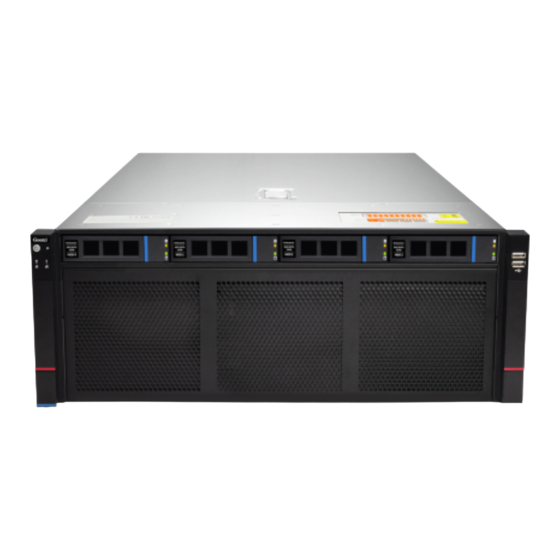
It is applicable in various scenarios, including big data analysis, 3D graphics applications, video decoding, deep learning, scientific computing, and more. 1.2 Product structure ASR4110G-D04R-G2 physical structure of the rear view is shown in the figure below: Structure Diagram 1-1... -
Page 6: Logical Structure
1.3 Logical structure G2DERO-B motherboard is shown in the figure below: DDR4 DIMM0 DDR 4 DIMM0 CH_A CH_A x16 xGMI DDR 4 DIMM0 DDR4 DIMM0 CH_B CH_B CPU0 CPU1 DDR 4 DIMM0 DDR4 DIMM0 x16 xGMI CH_C CH_C DDR 4 DIMM0 DDR4 DIMM0 CH_D CH_D... -
Page 7: Product Specifications
1.4 Product Specifications Product Line ASR4110G-D04R-G2 ASR4110G-D10R-G2 Product Type 4U10-GPU 4-bay rackmount server 4U10-GPU 10-bay rackmount server System Size 790mm*433mm*176.5mm (D*W*H) Processor* Support 2 AMD EPYC 7003/7002/7001 series processors Support 16pcs DDR4 ECC RDIMM/LRDIMM memory, memory frequency support 2133/2400/2666/2933MHz, support a single maximum capacity of 256GB, and a Memory maximum total memory capacity of 4TB. -
Page 8: Front Panel
2.1 Front panel 2.1.1 Appearance ⚫ 4 x 3.5 inch hard drive configuration Figure 2-1 Name Name switch panel USB 2.0 interface 3. 5 inch hard drive table 2-1 2.1.2 Indicator lights and buttons Figure 2-2... - Page 9 Indicator light /button Indicator light /button Power switch System Alarm Indicator button/indicator Restart button Network port 1 connection status indicator Hard drive indicator Network port 2 connection status indicator LED status description logo Indicator light status description /button Description of the power indicator light: Green (steady on): Indicates that the device has been powered on normally.
-
Page 10: Interface
2.1.3 Interface ⚫ Interface location Figure 2-3... -
Page 11: Rear Panel
Name USB interface Table 2-3 ⚫ Interface Description Name Type Quantity Description USB interface For accessing USB devices USB 2.0 Table 2-4 2.2 Rear panel 2.2.1 Appearance ⚫ Appearance of the rear panel Figure 2-4 Name Name power module 8038 Fan module 2.5-inch hard drive module expansion slot I / O panel... -
Page 12: Indicator Lights And Buttons
2.2.2 Indicator lights and buttons ⚫ Rear Panel Indicators Figure 2-5 Name Name Power module indicator Network port connection status indicator Management network port Network port data transmission connection status indicator status indicator Management network port data UID indicator transmission status indicator Table 2-6 ⚫... -
Page 13: Interface
⚫ When configuring 1 processor, it needs to be installed in CPU 0 position. ⚫ The processors configured in the same server must have the same model. ⚫ Please consult with Gooxi sales for specific system options available. 2.4 Memory 2.4.1 Memory slot location... -
Page 14: Memory Compatibility Information
memory slot location ⚫ Figure 2-7 2.4.2 Memory Compatibility Information Motherboard supports DDR4 RDIMM/LRDIMM Server memory, memory frequency supports 2133/2400/2666/2933 MHz. Note: ⚫ The same server must use the same model of DDR4 memory, and all memory must run at the same speed. Likewise, the velocity value is the lowest of the following: ⚫... -
Page 15: Hard Drive Distribution
2*SAS/SATA hard drives Support 2 or 4 2.5-inch SAS hard drives need to be in the rear or SAS/SATA hard paired with a SAS pass- drives through card or RAID card for 4*SAS/SATA hard drives (optional) support 2* NVMe hard drives Support 2 or 4*2.5-inch U.2 hard drive needs to be (optional) or 4 *NVMe... -
Page 16: Hard Drive Status Indicator
2.5.3 Hard drive Status Indicator Figure 2-10 ⚫ Hard drive status indicator description Function Act LED Status LED Fault LED Hard drive in always on position Hard drive always on activity Hard drive always on Blinking 4Hz/second location Hard drive error always on always on RAID rebuild... -
Page 17: Power Supply
⚫ When configuring power modules in the same server, the power module models must be the same ⚫ For specific optional system components available for purchase, please consult Gooxi sales 2.7 Fan ⚫ Support 11 fan modules ⚫ Support hot swap ⚫... -
Page 18: Pcie Slot Description
2. 8.2 PCIe slot description When CPU1 is not present, its corresponding PCIe slot is unavailable. PCIe slot Slot size Secondary PCIe standard Bus bandwidth Slot 1 PCIe 4.0 half height half CPU 1 x8 _ length Slot 2 PCIe 4.0 half height half CPU 1 length... -
Page 19: Pcba
2.9 PCBA 2.9.1 Motherboard Motherboard Figure 2-12 Module Name Chassis fan control 4 pin interface (8) ATX 8PIN power connector ATX 8PIN power connector PMBUS ATX 6PIN power connector ATX 6PIN power connector ATX 24PIN power connector Mini SAS HD1/HD2 8643 connector M.2 slot LPC TPM/80Port 2x10PIN Header FP USB3.0*2 Header... - Page 20 RJ45 Gigabit network port COM port and VGA UID button SLOT10 PCIE X16 SLOT 9 PCIE X8 SLOT 8 PCIE X8 SLOT7 PCIE X16 SLOT6 PCIE X16 SLOT5 PCIE X8 SLOT4 PCIE X8 or X16 SLOT3 PCIE X8 or null SLOT2 PCIE X16 SLOT1 PCIE X8 Front panel pins...
-
Page 21: Hard Drive Backplane
2.9.2 Hard drive backplane ⚫ 2×2.5 rear hard drive backplane (SAS/SATA) TOP surface Figure 2-13 Description Function 7PIN SATA interface SATA drive signal cable interface power interface Backplane power transmission connector, used for the transmission of 12 V power 7PIN SATA interface SATA drive signal cable interface Table 2-13 Bottom surface... -
Page 22: Installation Of Accessories
3.1 Installation of Accessories 3.1.1 Installation of CPU Before starting the CPU installation, please read the following guidelines: ⚫ Make sure the motherboard supports the CPU. ⚫ Before installing the CPU, be sure to turn off the computer and unplug the power cord from the power outlet to prevent hardware damage. - Page 23 Figure 3-1 Figure 3-2 Figure 3-3...
-
Page 24: Installation Of Heatsink
3.1.2 Installation of heatsink Before starting to install the heatsink, please read the following guidelines: ⚫ Before installing the heatsink, please be sure to turn off the computer and unplug the power cord from the power outlet to prevent damage to the hardware. ⚫... -
Page 25: Installation Of Memory
3.1.4 Installation of memory The motherboard supports 8 DDR4 channels, each channel supports 1 DIMM, and 2 CPUs support a total of 16 DDR4 slots (When only one memory is inserted, it is preferred to insert the slot in the red frame in the figure below). - Page 26 Figure 3-7 ⚫ Step 2: Fix the inner rails on both sides of the chassis. ⚫ Step 3: Install the outer rail on the cabinet bracket and secure the screws. Figure 3-8 Note: When installing the guide rail, you need to align with the U mark. When you hear a snap, install it in place, and use M5 screws to fix it.
-
Page 27: Initial Configuration
4.1 Initial Configuration 4.1.1 Power on the system ⚫ Before powering on, ensure that all server configurations are installed according to the corresponding specifications and standards, and the server is powered off but remains connected to the power source. Additionally, ensure that all cables are properly connected, and the power supply voltage matches the requirements of the equipment. -
Page 28: Initial Data
4.1.2 Initial data ⚫ BMC default account: admin ⚫ BMC default password: Gooxi @123. ⚫ BMC default address: 192.168. x. x ⚫ BIOS default password: none 4.1.3 Configuration of BIOS Upon entering the BIOS Setup interface, the following is displayed:... - Page 29 ⚫ After powering on the server, pay attention to the POST process during startup. On the logo screen, in the lower left corner, the IP address is displayed. ⚫ After powering on the server, pay attention to the POST process. Press the <DEL>...
- Page 30 Unspecified: Do not change the BMC parameters Static: BIOS static IP setting DynamicBmcDhcp: BMC is running DHCP for dynamic IP allocation. DynamicBmcNonDhcp: BMC is running a non-DHCP protocol for dynamic IP allocation. Default value: Unspecified ⚫ After modifying from Unspecified to other parameters, saving and restarting, the option will revert to the Unspecified value.
- Page 31 Log in to the BMC management interface. Enter the IP address on the web page, as shown in the figure: Figure 4-4 After entering the account and password, you will enter the home page, where you can perform BMC IP address configuration in the management interface. On the left side of the interface, switch to "Settings Page"...
-
Page 32: Appendix
⚫ Try reseating the RAID card and PCIe adapter to confirm if they are functioning correctly. ⚫ If the issue persists even after replacing the RAID card with a known working one, restore to factory settings and update the BIOS version. Contact Gooxi technical support for further assistance. IPMI Connection Failure ⚫... - Page 33 ⚫ Set static or dynamic IP and ensure ping connectivity. If the web interface does not open, try using a newer version of Internet Explorer. ⚫ If the problem is not resolved, please contact Gooxi technical support for further assistance.
Need help?
Do you have a question about the ASR4110G-D04R-G2 and is the answer not in the manual?
Questions and answers