Table of Contents
Advertisement
Advertisement
Table of Contents

Related Manuals for Gooxi SY103-S06R-G2


Summary of Contents for Gooxi SY103-S06R-G2
- Page 1 SY103-S06R-G2 Gooxi Micro Blade Server Barebone User operation manual Rev 0.1...
- Page 2 It mainly introduces and describes the characteristic parameters, system configuration and installation method of this product. This mini-server of Gooxi supports up to 3 nodes. The system is based on 1U3. Chassis and G2SCN-4B motherboard integration. This manual is for reference by professional system integrators and personal computer technicians.
-
Page 3: Table Of Contents
Chapter 4 Server System Installation This chapter describes the necessary steps and precautions for using the SY103-S06R-G2 Micro Server barebones system. Contents Chapter 1 Product Introduction ......................5 1.1 System Features ......................... - Page 4 3.1 CPU installation ........................ 32 3.2 CPU Heatsink Installation ..................... 34 3.3 Memory Installation ....................... 35 3.4 Hard Disk Installation ..................... 37 Chapter 4 Server System Installation ....................40 4.1 Overview ..........................40 4.2 System Steps ........................41 Shenzhen Gooxi Technology Co., Ltd.
-
Page 5: Chapter 1 Product Introduction
One Supports 1 Standard Transverse PCI-EX16 Expansion Card expansion card Supports one PCIEX2 M.2 SSD and SATA M.2 SSD Single-node C232 for 4*SATA3.0, C236 for 6*SATA3.0, SATA 3.5 inch support RAID 0,1; 2.5 inch support RAID 0,1,5,10 Shenzhen Gooxi Technology Co., Ltd. - Page 6 1U Rack Mount, 800mm*448mm*43.5mm 1.1.2 System Overview The Gooxi SY103-S06R-G2 Microblade Server Barebone is a high-density server product (Micro-Cloud Server). This design supports hot plugging of three server nodes in a 1U chassis height. Each node system can be used independently. You can configure the number of server nodes as needed.
-
Page 7: Board Features
Intel Xeon processor E3-1200 V5/V6 series processor Intel 6th Generation Core i3 series Pentium series; Celeron series Socket LGA1151 up to 80W CPU chipset Intel PCH Lynxpoint C23X Memory Single node supports up to 64GB ECC DDR4-1600/1866/2133 Shenzhen Gooxi Technology Co., Ltd. -
Page 8: Server Chassis System Features
IPMI 2.0 + KVM with dedicated LAN;Watch Dog interface 1.2.2 motherboard hardware chip features diagram: 1.3 server chassis System Features 1.3.1 Chassis Parameters Basic parameters Chassis style cabinet type Chassis structure Adapt to the G2SCN-4B Shenzhen Gooxi Technology Co., Ltd. -
Page 9: System View
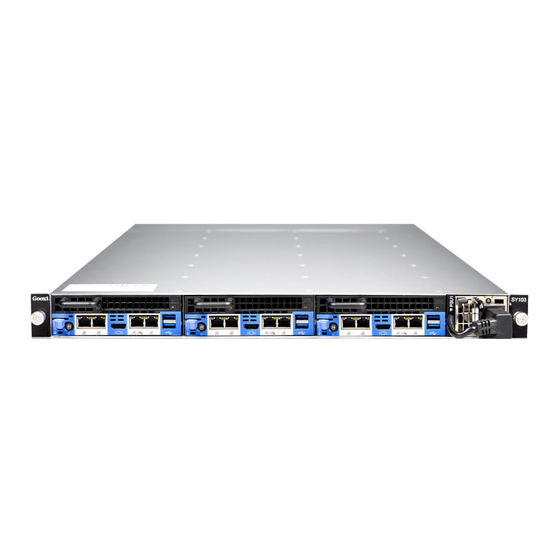
Voltage: 10.8~12.6V, current: 0.85A, maximum 1.02A. Power: 10.2W, maximum 12.24W. Maximum speed: 13600RPM front, 12400RPM rear. Air flow: 0.8 m3/min (28.26 CFM), minimum 0.72 m3/min (25.43 CFM). Pressure: MIN 340Pa, MAX 420Pa. 1.4 System View 1.4.1 Front View Shenzhen Gooxi Technology Co., Ltd. - Page 10 1.4.2 Rear view 1.4.3 Side view /Precautions: 1. The above is a system view with three nodes and three nodes in total. Users can, of course, choose the number of nodes they need based on actual needs. Shenzhen Gooxi Technology Co., Ltd.
-
Page 11: Chapter Ii System Interface Introduction
The main board is the main component of the system. The main interface of the system is on the main board. First of all, it is necessary to understand the interface layout of the main board. 2.1.1 G2SCN-4B MOTHERBOARD REAL PICTURE Shenzhen Gooxi Technology Co., Ltd. - Page 12 2.1.2 G2SCN-4B MOTHERBOARD INTERFACE AND DEFINITION MOTHERBOARD INTERFACE LOCATION DIAGRAM Shenzhen Gooxi Technology Co., Ltd.
- Page 13 2. Motherboard interface definition: Shenzhen Gooxi Technology Co., Ltd.
- Page 14 I210 1000M Data LAN port 1 LAN1/NCSI Simultaneously use BCSI IPMI LAN port (100M) through NCSI LAN2 I210 1000M Data LAN port 2 I210 1000M Data LAN port 3 (This port is not available when LAN3 G2SCN-2B supports 10G card) Shenzhen Gooxi Technology Co., Ltd.
-
Page 15: Motherboard Io Interface
Signal Pin Pin 2.2 Motherboard IO Interface 2.2.1 N ODE BUTTON Node switch button In the front of the chassis, press the button to start the node system. The position indicates the blue arrow below Shenzhen Gooxi Technology Co., Ltd. - Page 16 The specific location of the board on the main board is as follows. On the back of the motherboard, the Bottom layer is marked with the D14 position: Shenzhen Gooxi Technology Co., Ltd.
- Page 17 CAT5 and above cables. The switch can also be directly connected to the customer's host, supporting Gigabit, 100M, and adaptive adjustment, but it can not be used as a service data network port. The LED indicators of the network port are as follows: Shenzhen Gooxi Technology Co., Ltd.
- Page 18 The CAT5 is used. And above the cable access switch, you can also directly connect to the customer's host. The LED indicators of the network port are as follows: Business Data LAN Port Led description Left Led Link status indicator: Shenzhen Gooxi Technology Co., Ltd.
- Page 19 PIN sequence description PIN1,5 PIN2,6 PIN3,7 PIN4,8 Ground Location map: 2.2.7 HDMI DISPLAY INTERFACE The on-board HDMI connector is actually a VGA signal and requires a switching cable. In particular, Pin is defined as follows: Shenzhen Gooxi Technology Co., Ltd.
- Page 20 C236 Chipset, There are 6 SATA Connectors for SATA1~SATA6; the location diagrams are as follows: SATA Connector Pin Definition PIN sequence description PIN1 Ground PIN2 SATA HOST TX+ PIN3 SATA HOST TX- PIN4 Ground Shenzhen Gooxi Technology Co., Ltd.
- Page 21 5V_SB PIN2 PIN3 PIN4 PIN5 Ground PIN6 Ground PIN7 Ground PIN8 Ground 2.2.12 ATX 8PIN POWER CONNECTOP (OUT) NTRODUCTION J2 is a black ATX 8PIN POWER Connector. It is used to connect the SATA hard Shenzhen Gooxi Technology Co., Ltd.
- Page 22 NODE ID number PIN6 PM2_SMB_ALERT_N PSU2 alarm signal PIN7 NODE_ID_1 Used to identify the NODE ID number PIN8 PM1_SMB_ALERT_N PSU1 alarm signal PIN9 NODE_ID_2 Used to identify the NODE ID number PIN10 BMC_I2C_SCL_5 I2C clock signal Shenzhen Gooxi Technology Co., Ltd.
- Page 23 Channel B. Each channel has two DIMM SLOTs, J6 and J7 are Channel A DIMM slots, and J8 and J9 are Channel B slots. / Note: If only one DIMM is inserted in each Channel, it needs to be inserted in the slot away from the CPU. Shenzhen Gooxi Technology Co., Ltd.
- Page 24 LGA1151 CPU. During the installation of the CPU, attention should be paid to the installation of the first PIN. The first PIN is as follows: The red circle below shows the first PIN, as shown by the triangular arrows. Corresponding to the CPU triangle arrow. Shenzhen Gooxi Technology Co., Ltd.
-
Page 25: Connection Cable
In the cable part, we have 5 different cables, which are 2 SATA high-speed cables, 1 motherboard to get 12V and 5V_SB electrical cables from the backplane, 1 cable to transfer the motherboard 12V/5V power to the hard drive, and 1 cable 20-pin motherboard and backplane signal communication cable. Shenzhen Gooxi Technology Co., Ltd. -
Page 26: Jumper Settings
Firmware update and upgrade is not limited, under normal circumstances, can not be shorted. J13 introduction: Use 2PIN adjustment cap to insert J13, then use Clear CMOS. The above 3 pin positions are as follows: Shenzhen Gooxi Technology Co., Ltd. -
Page 27: Power Module
Rear IO that indicate the UID LED of the main board ID and the HDD LED of the main board's hard disk, three BMC heartbeat indicator LEDs, the motherboard PWR OK LED, and the CPLD heartbeat indicator. . 1. UID LED UID LED description Shenzhen Gooxi Technology Co., Ltd. - Page 28 Drop UID LED. 2. BMC Heart LED BMC Heart LED description Green light flashes at 1Hz Firmware initialization OK This indicator cannot be lit Firmware did not complete initialization 3. Motherboard PWR OK LED Shenzhen Gooxi Technology Co., Ltd.
- Page 29 Green LED is off off state abnormal Onboard power Green LED (D4) is always on green Board power is Green LED (D4) is off off state not OK 5. Board Power OK LED Shenzhen Gooxi Technology Co., Ltd.
- Page 30 SATA HDD/M.2 SSD in place but Green LED is always D5 (front) no data activity green SATA HDD/M.2 SSD has data Green LED blinks activity SATA HDD/M.2 SSD is not in Green LED off place Shenzhen Gooxi Technology Co., Ltd.
-
Page 31: Chapter 3 Detailed Node Installation
Chapter 3 Detailed Node Installation This chapter describes the installation steps of the main components on the Shenzhen Gooxi Technology Co., Ltd. -
Page 32: Cpu Installation
Guoxin certified heat sink. Detailed installation of LGA1151 processor steps: Press gently on the platen and push outward (to the right) to unlock. Once the platen handle is unlocked, gently lift the handle to open the platen. Shenzhen Gooxi Technology Co., Ltd. - Page 33 No effort is required to close the carrier plate. Press the carrier plate, close and hold the socket lever. Shenzhen Gooxi Technology Co., Ltd.
-
Page 34: Cpu Heatsink Installation
CPU is properly aligned and securely seated in the socket before opening the platen. 3.2 CPU Heatsink Installation Remove the heat sink and apply the appropriate amount of hot silicone paste to the bottom of the heat sink. Shenzhen Gooxi Technology Co., Ltd. -
Page 35: Memory Installation
OW TO INSTALL MEMORY Motherboard DIMM slot order: DIMMA1, DIMMB1, DIMMA0, and DIMMB0, pay attention to the memory slot is consistent with the DIMM slot gap to prevent incorrect installation. Vertically snap each DIMM module into place. Shenzhen Gooxi Technology Co., Ltd. - Page 36 Simulate the demo diagram inserted into the memory bar: Removal: Use your thumb to gently push the release tab near both ends of the memory module socket to release the memory from the socket. Simulate the demo picture of disassembling the memory: Shenzhen Gooxi Technology Co., Ltd.
-
Page 37: Hard Disk Installation
Hold the release tab above the node, pull the node's handle, and pull it out of the system. The installed hard disk screw holes are aligned with those on the back of the node sliding rail bracket. The following figure shows the installation of a 3.5-inch hard disk: Shenzhen Gooxi Technology Co., Ltd. - Page 38 The following figure shows the installation of a 2.5-inch hard disk: Shenzhen Gooxi Technology Co., Ltd.
- Page 39 When the installation of the hard disk is complete, push the sliding rail bracket back into the system enclosure, as shown in the following diagram: 3.5-inch hard disk for example. Shenzhen Gooxi Technology Co., Ltd.
-
Page 40: Chapter 4 Server System Installation
Chapter 4 Server System Installation 4.1 Overview This section describes the procedures for using the GOOXI SY103-S06R-G2 mini server barebone system. Select an appropriate location on the cabinet to place the server system. This location should meet the following conditions: clean, well-ventilated, dust-free or... -
Page 41: System Steps
4.2 System Steps GOOXI Rails Use the following steps to install the system into the cabinet. As shown in the figure below, align the screw holes, and fix the two screws on the front and back of each rail and the cabinet. The positions of the holes are the same. - Page 42 Hold the system up and place the system horizontally into the rails and push it into the cabinet. After the system is well-armed, lock the captive screws on the system panel, as shown in the arrow below. Shenzhen Gooxi Technology Co., Ltd.
- Page 43 Supports up to 192GB ECC DDR4-1600/1866/2133 UDIMMs power supply The system uses a 500W gold power efficiency power supply and supports 1+1 redundancy System size 800mm*448mm*43.5mm (deep * wide * high) System weight Net weight 14 kg, gross weight 17 kg Shenzhen Gooxi Technology Co., Ltd.
- Page 44 Power The system uses a 500W gold power efficiency power supply and Features supports 1+1 redundancy Input voltage 100-240V 47Hz~63Hz。 output +12V,+5V_SB voltage System fan Number System supports 6 4056 temperature controlled fans fans Shenzhen Gooxi Technology Co., Ltd.
- Page 45 Linux Kernel Virtual Machine (Target) System ambient temperature System Operating temperature: 10°C ~ 35°C; non-operating temperature: operating -40°C ~ 70°C temperature System Operating humidity: 35%~80%; Non-operating humidity: 20% ~ temperature and humidity Safety certification Certified CE ROHS Shenzhen Gooxi Technology Co., Ltd.
Need help?
Do you have a question about the SY103-S06R-G2 and is the answer not in the manual?
Questions and answers